Service Manual
Page 4
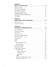
... Resource Conflicts 2-5 Running the Diskette-Based Diagnostics 2-5 Getting Help 2-6 Chapter 3 Beep Codes and Error Messages 3-1 POST Beep Codes 3-1 System Error Messages 3-3 Chapter 4 Removing and Replacing Parts 4-1 Recommended Tools 4-1 Precautionary Measures 4-2 Floor Stand 4-3 System Unit Cover 4-4 Eject, Power, and Reset Buttons 4-5 Front-Panel Inserts 4-6 Indicator Card 4-7 Speaker 4-8 Drives 4-9 Drives in the Drive...
... Resource Conflicts 2-5 Running the Diskette-Based Diagnostics 2-5 Getting Help 2-6 Chapter 3 Beep Codes and Error Messages 3-1 POST Beep Codes 3-1 System Error Messages 3-3 Chapter 4 Removing and Replacing Parts 4-1 Recommended Tools 4-1 Precautionary Measures 4-2 Floor Stand 4-3 System Unit Cover 4-4 Eject, Power, and Reset Buttons 4-5 Front-Panel Inserts 4-6 Indicator Card 4-7 Speaker 4-8 Drives 4-9 Drives in the Drive...
Service Manual
Page 31
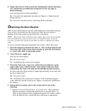
... diagnostics diskette into drive A. Does the fan run normally? No. It may be necessary to reboot the system several times in Chapter 4, "Removing and Replacing Parts." No. 8. No. Check the power supply fan. Basic Troubleshooting 2-3 Proceed to step 4. To observe problem indications during the boot routine, troubleshoot the diskette drive or...
... diagnostics diskette into drive A. Does the fan run normally? No. It may be necessary to reboot the system several times in Chapter 4, "Removing and Replacing Parts." No. 8. No. Check the power supply fan. Basic Troubleshooting 2-3 Proceed to step 4. To observe problem indications during the boot routine, troubleshoot the diskette drive or...

Service Manual
Page 45
...chapter. • You have removed the system unit cover. • You can replace or reinstall a part by performing the removal procedure in the next section, "Precautionary Measures." Removing and Replacing Parts 4-1 Recommended Tools Most of the following tools: • Small flat-blade screwdriver • Wide flat-blade... pliers Also, use a wrist grounding strap as explained in reverse order unless additional information is provided. Chapter 4 Removing and Replacing Parts This chapter provides procedures for removing the components, assemblies, and subassemblies in the system unit.
...chapter. • You have removed the system unit cover. • You can replace or reinstall a part by performing the removal procedure in the next section, "Precautionary Measures." Removing and Replacing Parts 4-1 Recommended Tools Most of the following tools: • Small flat-blade screwdriver • Wide flat-blade... pliers Also, use a wrist grounding strap as explained in reverse order unless additional information is provided. Chapter 4 Removing and Replacing Parts This chapter provides procedures for removing the components, assemblies, and subassemblies in the system unit.

Service Manual
Page 47
Floor Stand Removal To remove the floor stand, follow these steps: 1. Unscrew the floor stand screw. Disengage the three orientation nubs that position and help hold the floor stand to unscrew the floor stand screw. Use your fingers or a wide flat-blade screwdriver to the system unit. The screw is captured and separated from the system unit. Place left side of the system unit on a flat work surface. 2. Removing and Replacing Parts 4-3 Floor Stand floor stand screw Figure 4-1. Pull the floor stand away from the floor stand. 3.
Floor Stand Removal To remove the floor stand, follow these steps: 1. Unscrew the floor stand screw. Disengage the three orientation nubs that position and help hold the floor stand to unscrew the floor stand screw. Use your fingers or a wide flat-blade screwdriver to the system unit. The screw is captured and separated from the system unit. Place left side of the system unit on a flat work surface. 2. Removing and Replacing Parts 4-3 Floor Stand floor stand screw Figure 4-1. Pull the floor stand away from the floor stand. 3.

Service Manual
Page 48
...until the cover is installed. System Unit Cover securing button front of system unit Figure 4-3. Four plastic hooks on the inside the system unit. 4-4 Dell OptiPlex GXpro Systems Service Manual back of system unit Figure 4-2. Lift the cover, from the back, pivoting it to swing up. 3. Before you reinstall the cover...fold all cables out of the way so that they do not interfere with the cover or with the proper airflow inside of the front part of the cover secure it toward the front of the system unit. Padlock Removal 2. System-Unit Cover Removal To remove the system unit...
...until the cover is installed. System Unit Cover securing button front of system unit Figure 4-3. Four plastic hooks on the inside the system unit. 4-4 Dell OptiPlex GXpro Systems Service Manual back of system unit Figure 4-2. Lift the cover, from the back, pivoting it to swing up. 3. Before you reinstall the cover...fold all cables out of the way so that they do not interfere with the cover or with the proper airflow inside of the front part of the cover secure it toward the front of the system unit. Padlock Removal 2. System-Unit Cover Removal To remove the system unit...

Service Manual
Page 49
... facing you. 2. To remove the power button or the reset button, use a small screwdriver and push in on the plastic part of the cover. When these steps: 1. Removing and Replacing Parts 4-5 To remove the 3.5-inch diskette-drive eject button, pull gently on the two or three plastic clips that hold the button...
... facing you. 2. To remove the power button or the reset button, use a small screwdriver and push in on the plastic part of the cover. When these steps: 1. Removing and Replacing Parts 4-5 To remove the 3.5-inch diskette-drive eject button, pull gently on the two or three plastic clips that hold the button...

Service Manual
Page 51
... chassis. 5. Indicator Card Removal speaker connector To remove the indicator card, follow these steps: 1. Remove the speaker connector from the system board. Removing and Replacing Parts 4-7 Indicator Card chassis hook (2) indicator card screw indicator card cable Figure 4-6. See "Drives" found later in the bottom of the hooks holding the indicator card...
... chassis. 5. Indicator Card Removal speaker connector To remove the indicator card, follow these steps: 1. Remove the speaker connector from the system board. Removing and Replacing Parts 4-7 Indicator Card chassis hook (2) indicator card screw indicator card cable Figure 4-6. See "Drives" found later in the bottom of the hooks holding the indicator card...

Service Manual
Page 53
Drives Figure 4-8 shows an example of the procedures in the system unit. Refer to this figure when you perform any of drive hardware that can be installed in the following subsections. Drive Hardware IDE1 connector Removing and Replacing Parts 4-9 system power supply two-bay DC power cable drive cage diskette/tape drive interface cable 3.5-inch diskette drive CD-ROM/tape drive interface cable hard-disk drive bracket power input connectors DSKT connector IDE2 connector Figure 4-8.
Drives Figure 4-8 shows an example of the procedures in the system unit. Refer to this figure when you perform any of drive hardware that can be installed in the following subsections. Drive Hardware IDE1 connector Removing and Replacing Parts 4-9 system power supply two-bay DC power cable drive cage diskette/tape drive interface cable 3.5-inch diskette drive CD-ROM/tape drive interface cable hard-disk drive bracket power input connectors DSKT connector IDE2 connector Figure 4-8.

Service Manual
Page 55
Disconnect the DC power cable and the interface cable from the back of the drive bay, slide the drive forward, and remove it from the middle or lower drive bay, follow these steps: 1. Removing and Replacing Parts 4-11 Press out on the two retaining tabs on the sides of the drive. 2. retaining tab (2) Figure 4-10. 5.25-Inch Drive Removal To remove a 5.25-inch drive from the drive bay.
Disconnect the DC power cable and the interface cable from the back of the drive bay, slide the drive forward, and remove it from the middle or lower drive bay, follow these steps: 1. Removing and Replacing Parts 4-11 Press out on the two retaining tabs on the sides of the drive. 2. retaining tab (2) Figure 4-10. 5.25-Inch Drive Removal To remove a 5.25-inch drive from the drive bay.

Service Manual
Page 57
hard-disk drive drive-bracket mounting screw (4) hard-disk drive bracket Figure 4-12. See the preceding procedure. 2. Remove the hard-disk drive bracket from the system unit. Remove the four screws that secure the hard-disk drive(s) to the bracket. 3. Removing and Replacing Parts 4-13 Hard-Disk Drive Removal To remove a hard-disk drive, follow these steps: 1. Slide the drive(s) out of the hard-disk drive bracket.
hard-disk drive drive-bracket mounting screw (4) hard-disk drive bracket Figure 4-12. See the preceding procedure. 2. Remove the hard-disk drive bracket from the system unit. Remove the four screws that secure the hard-disk drive(s) to the bracket. 3. Removing and Replacing Parts 4-13 Hard-Disk Drive Removal To remove a hard-disk drive, follow these steps: 1. Slide the drive(s) out of the hard-disk drive bracket.

Service Manual
Page 59
See "System Power Supply," found earlier in this chapter. 2. Removing and Replacing Parts 4-15 Sqeeze the latch and pull out the fan power cable from the microprocessor fan connector located on the fan to disengage the four latching ...
See "System Power Supply," found earlier in this chapter. 2. Removing and Replacing Parts 4-15 Sqeeze the latch and pull out the fan power cable from the microprocessor fan connector located on the fan to disengage the four latching ...

Service Manual
Page 61
Dell recommends that the lever engages the notch when the lever is depressed. Disconnect any cables from the system unit. Lift the expansion-card cage up and away from the expansion cards and the riser board. 2. Removing and Replacing Parts 4-17 To replace an expansion-card cage, keep the cage flush against the...
Dell recommends that the lever engages the notch when the lever is depressed. Disconnect any cables from the system unit. Lift the expansion-card cage up and away from the expansion cards and the riser board. 2. Removing and Replacing Parts 4-17 To replace an expansion-card cage, keep the cage flush against the...

Service Manual
Page 63
... from the expansion-card cage. Riser Board retaining screw (2) slot (2) expansion-card cage riser board Figure 4-18. See the preceding two procedures. 2. Removing and Replacing Parts 4-19 On a flat work surface, turn the expansion-card cage over, with the riser board facing you. 3. Lift the riser board away from the two...
... from the expansion-card cage. Riser Board retaining screw (2) slot (2) expansion-card cage riser board Figure 4-18. See the preceding two procedures. 2. Removing and Replacing Parts 4-19 On a flat work surface, turn the expansion-card cage over, with the riser board facing you. 3. Lift the riser board away from the two...

Service Manual
Page 65
.../heat sink assembly. Push outward and then upward on socket (front and back) release lever microprocessor Figure 4-21. Removing and Replacing Parts 4-21 WARNING: The microprocessor chip can get extremely hot during system operations. To install the replacement microprocessor/heat sink assembly, ensure that...on the corner with a small screwdriver to easily slip into the socket. When the microprocessor/heat sink assembly is located on the folded part of the system board, and then snap it . NOTE: Pin 1 on the microprocessor is in place, rotate the microprocessor release lever...
.../heat sink assembly. Push outward and then upward on socket (front and back) release lever microprocessor Figure 4-21. Removing and Replacing Parts 4-21 WARNING: The microprocessor chip can get extremely hot during system operations. To install the replacement microprocessor/heat sink assembly, ensure that...on the corner with a small screwdriver to easily slip into the socket. When the microprocessor/heat sink assembly is located on the folded part of the system board, and then snap it . NOTE: Pin 1 on the microprocessor is in place, rotate the microprocessor release lever...

Service Manual
Page 67
... card or a secondary microprocessor (dual-processing systems) on an add-in card installed on the card to free it from the connector. Removing and Replacing Parts 4-23 This section describes removing and replacing the terminator card and the add-in the upgrade kit with the secondary microprocessor. Grasp the small white...
... card or a secondary microprocessor (dual-processing systems) on an add-in card installed on the card to free it from the connector. Removing and Replacing Parts 4-23 This section describes removing and replacing the terminator card and the add-in the upgrade kit with the secondary microprocessor. Grasp the small white...

Service Manual
Page 69
.... Insert the battery into its socket with your fingers or with the copy of the new battery exploding if it into position. 2. Removing and Replacing Parts 4-25 Replace the battery only with the "+" facing up. Restore any system configuration information that was lost while replacing the battery. System Battery battery BATTERY...
.... Insert the battery into its socket with your fingers or with the copy of the new battery exploding if it into position. 2. Removing and Replacing Parts 4-25 Replace the battery only with the "+" facing up. Restore any system configuration information that was lost while replacing the battery. System Battery battery BATTERY...

