Service Manual
Page 4
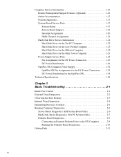
...-Supply Service Data 1-23 Pin Assignments for the DC Power Connectors 1-25 DC Power Distribution 1-26 OptiPlex NX Computer Power Supply 1-32 OptiPlex NX Pin Assignments for the DC Power Connectors . . . . 1-33 DC Power Distribution for the OptiPlex NX 1-34 Technical Specifications 1-36 Chapter 2 Basic Troubleshooting 2-1 Initial User Contact 2-1 External Visual Inspection 2-2 ...Based Diagnostics (Net PC Systems Only 2-7 Diskette-Based Diagnostics 2-9 Connecting an External Diskette Drive to the NX Computer 2-9 Running the Diskette-Based Diagnostics 2-10 Getting Help 2-11 vi
...-Supply Service Data 1-23 Pin Assignments for the DC Power Connectors 1-25 DC Power Distribution 1-26 OptiPlex NX Computer Power Supply 1-32 OptiPlex NX Pin Assignments for the DC Power Connectors . . . . 1-33 DC Power Distribution for the OptiPlex NX 1-34 Technical Specifications 1-36 Chapter 2 Basic Troubleshooting 2-1 Initial User Contact 2-1 External Visual Inspection 2-2 ...Based Diagnostics (Net PC Systems Only 2-7 Diskette-Based Diagnostics 2-9 Connecting an External Diskette Drive to the NX Computer 2-9 Running the Diskette-Based Diagnostics 2-10 Getting Help 2-11 vi

Service Manual
Page 12
Warnings, Cautions, and Notes Throughout this manual and the online System User's Guide, Dell provides the Diagnostics and Troubleshooting Guide for troubleshooting procedures and instructions on using the Dell Diagnostics to test the computer system. CAUTION: A CAUTION indicates either potential damage to hardware... A WARNING indicates the potential for bodily harm and provides instructions for how to avoid the problem. NOTE: A NOTE provides helpful information about using this manual to information provided in this manual, there may be blocks of IBM®-compatible PCs and prior ...
Warnings, Cautions, and Notes Throughout this manual and the online System User's Guide, Dell provides the Diagnostics and Troubleshooting Guide for troubleshooting procedures and instructions on using the Dell Diagnostics to test the computer system. CAUTION: A CAUTION indicates either potential damage to hardware... A WARNING indicates the potential for bodily harm and provides instructions for how to avoid the problem. NOTE: A NOTE provides helpful information about using this manual to information provided in this manual, there may be blocks of IBM®-compatible PCs and prior ...

Service Manual
Page 59
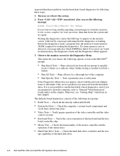
... their power sources, and turn them on the chassis. Does the problem appear to the next sections, "Eliminating Resource Conflicts," "Running Computer Diagnostics," and "Getting Help." Verify that they are fully seated in Chapter 4, 5, 6, or 7, as appropriate for your system. Basic Troubleshooting 2-5 3. Proceed to be resolved? Reinstall the computer cover. 7. The...
... their power sources, and turn them on the chassis. Does the problem appear to the next sections, "Eliminating Resource Conflicts," "Running Computer Diagnostics," and "Getting Help." Verify that they are fully seated in Chapter 4, 5, 6, or 7, as appropriate for your system. Basic Troubleshooting 2-5 3. Proceed to be resolved? Reinstall the computer cover. 7. The...
Service Manual
Page 62
Press immediately after you see "Getting Help" found later in this chapter. This menu lets you...system. 2. Checks the functionality of the mouse controller and the operation of the hard-disk drive 2-8 Dell OptiPlex GXa and OptiPlex NX Systems Service Manual suspected hardware problem, run the hard-disk-based diagnostics, and if you are ...; prompt: • Run Quick Tests - board controller chip • Mouse Test - Starting the diagnostics causes the Dell logo to isolate a failure • Run All Tests - The diskette-based diagnostics consists of main memory (RAM) required...
Press immediately after you see "Getting Help" found later in this chapter. This menu lets you...system. 2. Checks the functionality of the mouse controller and the operation of the hard-disk drive 2-8 Dell OptiPlex GXa and OptiPlex NX Systems Service Manual suspected hardware problem, run the hard-disk-based diagnostics, and if you are ...; prompt: • Run Quick Tests - board controller chip • Mouse Test - Starting the diagnostics causes the Dell logo to isolate a failure • Run All Tests - The diskette-based diagnostics consists of main memory (RAM) required...
Service Manual
Page 64
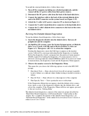
...failure or to indicate where further testing is needed to isolate a failure • Run All Tests - Starting the diagnostics causes the Dell logo to the DSKT connector on the monitor screen, followed by a message indicating that the diagnostics is detected, a message indicates which ..., see Figure 1-15). 4. Then press to the next section, "Getting Help." If no errors are found earlier in the online Network Administrator's Guide or online System User's Guide. 2-10 Dell OptiPlex GXa and OptiPlex NX Systems Service Manual Turn off the computer, including any attached peripherals, and...
...failure or to indicate where further testing is needed to isolate a failure • Run All Tests - Starting the diagnostics causes the Dell logo to the DSKT connector on the monitor screen, followed by a message indicating that the diagnostics is detected, a message indicates which ..., see Figure 1-15). 4. Then press to the next section, "Getting Help." If no errors are found earlier in the online Network Administrator's Guide or online System User's Guide. 2-10 Dell OptiPlex GXa and OptiPlex NX Systems Service Manual Turn off the computer, including any attached peripherals, and...

Service Manual
Page 65
For instructions, see "Contacting Dell" in the server-based, hard-disk-based, or diskette-based diagnostics reveals the source of the problem or leads to the proper troubleshooting steps for technical assistance. Basic Troubleshooting 2-11 Getting Help If none of the problem, call Dell for determining the source of the troubleshooting procedures in this chapter or the tests in the online Network Administrator's Guide or online System User's Guide.
For instructions, see "Contacting Dell" in the server-based, hard-disk-based, or diskette-based diagnostics reveals the source of the problem or leads to the proper troubleshooting steps for technical assistance. Basic Troubleshooting 2-11 Getting Help If none of the problem, call Dell for determining the source of the troubleshooting procedures in this chapter or the tests in the online Network Administrator's Guide or online System User's Guide.

Service Manual
Page 67
... in the computer diagnostics to assist in Table 3-1. See "Running Computer Diagnostics" in the case of the problem, run the appropriate tests to help isolate the source of computers. If the table does not lead to the source of some failures, during the POST or, in Chapter 2.... Chapter 3 Beep Codes and Error Messages This chapter describes the beep codes and error messages that are common to all members of the Dell OptiPlex GXa and OptiPlex NX family of the problem. Most beep codes indicate a fatal error that can occur during normal system operation. Beep Codes and Error ...
... in the computer diagnostics to assist in Table 3-1. See "Running Computer Diagnostics" in the case of the problem, run the appropriate tests to help isolate the source of computers. If the table does not lead to the source of some failures, during the POST or, in Chapter 2.... Chapter 3 Beep Codes and Error Messages This chapter describes the beep codes and error messages that are common to all members of the Dell OptiPlex GXa and OptiPlex NX family of the problem. Most beep codes indicate a fatal error that can occur during normal system operation. Beep Codes and Error ...

Service Manual
Page 80
... the two ring-tabs over the posts on the inside of the cover, use a 1/4-inch nutdriver to push inward on the ring-tabs. 4-6 Dell OptiPlex GXa and OptiPlex NX Systems Service Manual Lay the computer cover upside down ) 5.25-inch frontpanel insert posts (2) ring-tabs (2) Figure 4-4. From the front of ...the bay opening, and then press the ring-tabs over the posts. If necessary, use your thumbs to help push on the insert until it...
... the two ring-tabs over the posts on the inside of the cover, use a 1/4-inch nutdriver to push inward on the ring-tabs. 4-6 Dell OptiPlex GXa and OptiPlex NX Systems Service Manual Lay the computer cover upside down ) 5.25-inch frontpanel insert posts (2) ring-tabs (2) Figure 4-4. From the front of ...the bay opening, and then press the ring-tabs over the posts. If necessary, use your thumbs to help push on the insert until it...

Service Manual
Page 100
Disengage the three orientation nubs that position and help hold the floor stand to unscrew the floor stand screw. 3. Place the right side of the computer on a flat work surface. 2. Use your fingers or a wide flat-blade screwdriver to the computer. 5-4 Dell OptiPlex GXa and OptiPlex NX Systems Service Manual Floor Stand floor stand screw Figure 5-2. Pull the floor stand away from the computer. Floor Stand Removal 1. Unscrew the floor stand screw.
Disengage the three orientation nubs that position and help hold the floor stand to unscrew the floor stand screw. 3. Place the right side of the computer on a flat work surface. 2. Use your fingers or a wide flat-blade screwdriver to the computer. 5-4 Dell OptiPlex GXa and OptiPlex NX Systems Service Manual Floor Stand floor stand screw Figure 5-2. Pull the floor stand away from the computer. Floor Stand Removal 1. Unscrew the floor stand screw.

Service Manual
Page 103
From the front of the cover, use a 1/4-inch nutdriver to push inward on the ring-tabs. If necessary, use your thumbs to help push on the insert until it slides off the two posts. Front-Panel Insert Removal To remove a front-panel insert, follow these steps: 1. Removing and ...
From the front of the cover, use a 1/4-inch nutdriver to push inward on the ring-tabs. If necessary, use your thumbs to help push on the insert until it slides off the two posts. Front-Panel Insert Removal To remove a front-panel insert, follow these steps: 1. Removing and ...

Service Manual
Page 151
... front edge of the computer on the Net PC Chassis 7-3 The locator pins are keyed for correct installation. Disengage the locator pins that position and help secure the stand to the computer. Unscrew the captive screw using your fingers or a wide flat-blade screwdriver. 3. To remove the stand, if one is...
... front edge of the computer on the Net PC Chassis 7-3 The locator pins are keyed for correct installation. Disengage the locator pins that position and help secure the stand to the computer. Unscrew the captive screw using your fingers or a wide flat-blade screwdriver. 3. To remove the stand, if one is...
Service Manual
Page 168
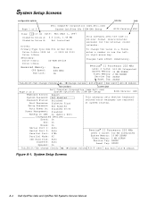
...seconds) for the internal clock/ calendar. To change values Alt-P next Esc exit Alt-B reboot Figure A-1. System Setup Screens A-2 Dell OptiPlex GXa and OptiPlex NX Systems Service Manual Pentium® II Processor 233 MHz Level 2 Cache: 512 KB Integrated System Memory: 16 MB SDRAM Video...field, enter a number or use the leftor right-arrow key. System Setup Screens configuration options title box help Page 1 of 2 Dell Computer Corporation (www.dell.com) System OptiPlex GXa 233M EM+ Setup BIOS Version: XXX Keyboard Errors: System Password: Password Status: Boot Sequence: Report ...
...seconds) for the internal clock/ calendar. To change values Alt-P next Esc exit Alt-B reboot Figure A-1. System Setup Screens A-2 Dell OptiPlex GXa and OptiPlex NX Systems Service Manual Pentium® II Processor 233 MHz Level 2 Cache: 512 KB Integrated System Memory: 16 MB SDRAM Video...field, enter a number or use the leftor right-arrow key. System Setup Screens configuration options title box help Page 1 of 2 Dell Computer Corporation (www.dell.com) System OptiPlex GXa 233M EM+ Setup BIOS Version: XXX Keyboard Errors: System Password: Password Status: Boot Sequence: Report ...
Service Manual
Page 176
..., 1-22 SMART technology, 1-4 hard-disk-drive assembly removal Net PC computer, 7-6 help, getting, 2-11 J jumpers list of, 1-20 location, 1-19 K key combination, to enter System Setup program, A-1 M main memory, 1-4, 1-16 manageability, enhanced, 1-1 memory subsystem expansion using DIMMs, 1-16 flash ROM, 1-4 main memory, 1-4 secondary L2 cache, 1-3, 1-16 4 Dell OptiPlex GXa and OptiPlex NX Systems Service Manual
..., 1-22 SMART technology, 1-4 hard-disk-drive assembly removal Net PC computer, 7-6 help, getting, 2-11 J jumpers list of, 1-20 location, 1-19 K key combination, to enter System Setup program, A-1 M main memory, 1-4, 1-16 manageability, enhanced, 1-1 memory subsystem expansion using DIMMs, 1-16 flash ROM, 1-4 main memory, 1-4 secondary L2 cache, 1-3, 1-16 4 Dell OptiPlex GXa and OptiPlex NX Systems Service Manual


