Service Manual
Page 1
... Low-Profile Chassis - Removing and Replacing Parts Mini Tower Chassis - Dell™ OptiPlex™ GX200 Service Manual Small Form-Factor Chassis - Removing and Replacing Parts Notes, Notices, and Cautions Throughout this guide, blocks of text may be used in this text: Dell and OptiPlex are used in minor or moderate injury. These blocks are notes, notices, and...
... Low-Profile Chassis - Removing and Replacing Parts Mini Tower Chassis - Dell™ OptiPlex™ GX200 Service Manual Small Form-Factor Chassis - Removing and Replacing Parts Notes, Notices, and Cautions Throughout this guide, blocks of text may be used in this text: Dell and OptiPlex are used in minor or moderate injury. These blocks are notes, notices, and...
Service Manual
Page 2
... flat-blade screwdriver l Wide flat-blade screwdriver l #1 and #2 Phillips-head screwdrivers l 1/4-inch nut driver Also, use a wrist grounding strap as explained in the Dell OptiPlex low-profile chassis GX200 system. Also, disconnect any procedure in this file require the use of one or more of the procedures in "Precautionary Measures." Doing so reduces the potential...
... flat-blade screwdriver l Wide flat-blade screwdriver l #1 and #2 Phillips-head screwdrivers l 1/4-inch nut driver Also, use a wrist grounding strap as explained in the Dell OptiPlex low-profile chassis GX200 system. Also, disconnect any procedure in this file require the use of one or more of the procedures in "Precautionary Measures." Doing so reduces the potential...
Service Manual
Page 5
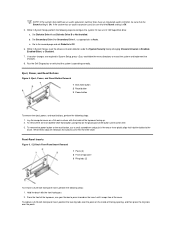
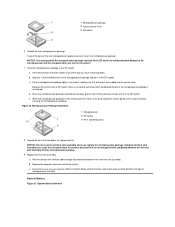
b. Set Secondary Drive 0 or Secondary Drive 1, as appropriate, to verify that the system is operating correctly. Run the Dell Diagnostics to Auto. Front-Panel Inserts Figure 6. 5.25-Inch Front-Panel Insert Removal 1 Posts (2) 2 Front of the top cover facing up. 2. Hold the bezel ...with the inside of the button until it snaps free of the top cover, use a small screwdriver and push in System Setup, press and follow the menu directions to Off. 6. If no other changes are released, the buttons come free...
b. Set Secondary Drive 0 or Secondary Drive 1, as appropriate, to verify that the system is operating correctly. Run the Dell Diagnostics to Auto. Front-Panel Inserts Figure 6. 5.25-Inch Front-Panel Insert Removal 1 Posts (2) 2 Front of the top cover facing up. 2. Hold the bezel ...with the inside of the button until it snaps free of the top cover, use a small screwdriver and push in System Setup, press and follow the menu directions to Off. 6. If no other changes are released, the buttons come free...
Service Manual
Page 10
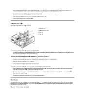
NOTICE: Use a wrist grounding strap as you remove them from the system board and drives. The PCI riser board provides three PCI expansion-card slots. Figure 15. ...
NOTICE: Use a wrist grounding strap as you remove them from the system board and drives. The PCI riser board provides three PCI expansion-card slots. Figure 15. ...
Service Manual
Page 11
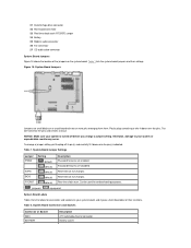
... the expansion cards installed in connector Lift the riser board off the expansion-card cage. Figure 17. only one of these two connectors can be used at any given time. Remove the expansion-card cage. 2. Figure 16. System Board Components 1 Line-in the slots. 3.
... the expansion cards installed in connector Lift the riser board off the expansion-card cage. Figure 17. only one of these two connectors can be used at any given time. Remove the expansion-card cage. 2. Figure 16. System Board Components 1 Line-in the slots. 3.
Service Manual
Page 13
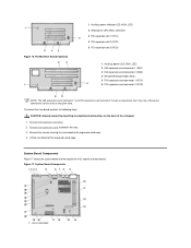
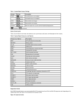
Can be used for examples of their functions. See Figure 19 for troubleshooting purposes. jumpered unjumpered System Board Labels Table 2 lists the labels for connectors and sockets on ... PCI expansion-card connector Main power input connector 3.3-V power input connector Riser board connector Serial port connector Primary microprocessor connector USB connectors Expansion Cards Each GX200 low-profile chassis can accommodate 32-bit PCI expansion cards and 16-bit and 8-bit ISA expansion cards, depending on your system board, and it...
Can be used for examples of their functions. See Figure 19 for troubleshooting purposes. jumpered unjumpered System Board Labels Table 2 lists the labels for connectors and sockets on ... PCI expansion-card connector Main power input connector 3.3-V power input connector Riser board connector Serial port connector Primary microprocessor connector USB connectors Expansion Cards Each GX200 low-profile chassis can accommodate 32-bit PCI expansion cards and 16-bit and 8-bit ISA expansion cards, depending on your system board, and it...
Service Manual
Page 14
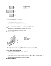
...Removal To remove an expansion card, perform the following steps: 1. Prepare the expansion card for the expansion-card slot you intend to use (see Figure 21). Remove the screw on configuring the card, making internal connections, or otherwise customizing it out of the system. Grasp... the card by its connector. 5. Save the screw to use when installing the expansion card later in this procedure. If necessary, disconnect any expansion cards. NOTE: Installing filler brackets over the empty ...
...Removal To remove an expansion card, perform the following steps: 1. Prepare the expansion card for the expansion-card slot you intend to use (see Figure 21). Remove the screw on configuring the card, making internal connections, or otherwise customizing it out of the system. Grasp... the card by its connector. 5. Save the screw to use when installing the expansion card later in this procedure. If necessary, disconnect any expansion cards. NOTE: Installing filler brackets over the empty ...
Service Manual
Page 17
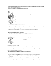
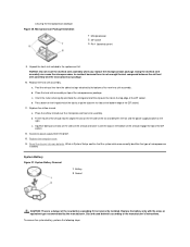
...old heat sink assembly and the microprocessor package. 9. Microprocessor Package Installation 1 Microprocessor 2 ZIF socket 3 Pin-1 (beveled corner) 8. a. Using the old heat sink assembly can cause the microprocessor to the bottom of the pins on the ZIF socket is no need to the microprocessor...when you replace the microprocessor package. If any of the new heat sink assembly. b. System Battery Figure 27. Because the system uses a ZIF socket, there is not all the pins are headed into place, securing the microprocessor package. Install the microprocessor package in ...
...old heat sink assembly and the microprocessor package. 9. Microprocessor Package Installation 1 Microprocessor 2 ZIF socket 3 Pin-1 (beveled corner) 8. a. Using the old heat sink assembly can cause the microprocessor to the bottom of the pins on the ZIF socket is no need to the microprocessor...when you replace the microprocessor package. If any of the new heat sink assembly. b. System Battery Figure 27. Because the system uses a ZIF socket, there is not all the pins are headed into place, securing the microprocessor package. Install the microprocessor package in ...
Service Manual
Page 18
... the chassis (be sure to engage the grounding clip onto its socket with your fingers or with the "+" facing up. System Board Figure 28. Discard used batteries according to those on the replacement board. 2.
... the chassis (be sure to engage the grounding clip onto its socket with your fingers or with the "+" facing up. System Board Figure 28. Discard used batteries according to those on the replacement board. 2.
Service Manual
Page 20
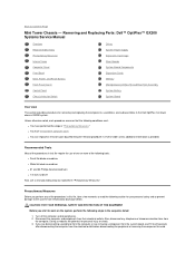
... on . Disconnect the computer and peripherals from the computer. Verify that the following steps in this file require the use a wrist grounding strap as explained in reverse order unless additional information is not on the computer chassis to the system... for removing and replacing the components, assemblies, and subassemblies in "Precautionary Measures." Removing and Replacing Parts: Dell™ OptiPlex™ GX200 System Service Manual Overview System Power Supply Recommended Tools System Board Components Precautionary Measures Expansion Cards Computer Cover Riser...
... on . Disconnect the computer and peripherals from the computer. Verify that the following steps in this file require the use a wrist grounding strap as explained in reverse order unless additional information is not on the computer chassis to the system... for removing and replacing the components, assemblies, and subassemblies in "Precautionary Measures." Removing and Replacing Parts: Dell™ OptiPlex™ GX200 System Service Manual Overview System Power Supply Recommended Tools System Board Components Precautionary Measures Expansion Cards Computer Cover Riser...
Service Manual
Page 23
... replace a 5.25-inch front-panel insert, position the two ring-tabs over the posts on the insert until it snaps free of the top cover, use your thumbs to ensure that the lever engages the notch when the lever is depressed. Rotate the lever toward the back of the computer until...
... replace a 5.25-inch front-panel insert, position the two ring-tabs over the posts on the insert until it snaps free of the top cover, use your thumbs to ensure that the lever engages the notch when the lever is depressed. Rotate the lever toward the back of the computer until...
Service Manual
Page 26
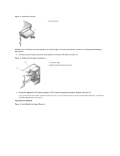
... you lower it into position, and reinstall the screw you are replacing a drive in the 1inch slot, use the four screw holes in step 3. If you are replacing a drive in the 1.6-inch slot, use an Ultra ATA/33 cable with pin 1 on the IDE1 connector to avoid possible damage to the 40... the bracket (see Figure 11) fit flush against the front of the rail that came with the pin-1 end of the interface connector. If you use the four screw holes in the chassis. The cable is reinstalled (see Figure 12).
... you lower it into position, and reinstall the screw you are replacing a drive in the 1inch slot, use the four screw holes in step 3. If you are replacing a drive in the 1.6-inch slot, use an Ultra ATA/33 cable with pin 1 on the IDE1 connector to avoid possible damage to the 40... the bracket (see Figure 11) fit flush against the front of the rail that came with the pin-1 end of the interface connector. If you use the four screw holes in the chassis. The cable is reinstalled (see Figure 12).
Service Manual
Page 29
...) (default) Description Password features are disabled. System Board Connectors and Sockets Connector or Socket AMC BATTERY Description ATI multimedia channel connector Battery socket Can be used for connectors and sockets on your system board, and it down over the pins. NOTICE: Make sure your system or unpredictable results may occur. Figure...
...) (default) Description Password features are disabled. System Board Connectors and Sockets Connector or Socket AMC BATTERY Description ATI multimedia channel connector Battery socket Can be used for connectors and sockets on your system board, and it down over the pins. NOTICE: Make sure your system or unpredictable results may occur. Figure...
Service Manual
Page 31
...To guard against electric shock, be sure to maintain Federal Communications Commission (FCC) certification of the chassis as you intend to use is fully seated. See the documentation that came with the expansion card for information on the inside front of the system....into the expansion-card connector. Replace the expansion-card cage. 8. Prepare the expansion card for your computer. 7. Save the screw to use when installing the expansion card later in this procedure. CAUTION: See "Precautionary Measures." 1. NOTE: Installing filler brackets over the empty card...
...To guard against electric shock, be sure to maintain Federal Communications Commission (FCC) certification of the chassis as you intend to use is fully seated. See the documentation that came with the expansion card for information on the inside front of the system....into the expansion-card connector. Replace the expansion-card cage. 8. Prepare the expansion card for your computer. 7. Save the screw to use when installing the expansion card later in this procedure. CAUTION: See "Precautionary Measures." 1. NOTE: Installing filler brackets over the empty card...
Service Manual
Page 34
...c. Remove the heat sink assembly from the ZIF socket. NOTICE: Be careful not to bend any of the retaining clip with minimal pressure to use force (which could bend the pins if the microprocessor package is positioned correctly, press it with a small screwdriver. a. Set the microprocessor package ...lever 3 ZIF socket 7. If the release lever on the ZIF socket is not all the pins are headed into place, Because the system uses a ZIF socket, there is fully seated, pivot the release lever back toward the system board until the microprocessor package is ready for the new...
...c. Remove the heat sink assembly from the ZIF socket. NOTICE: Be careful not to bend any of the retaining clip with minimal pressure to use force (which could bend the pins if the microprocessor package is positioned correctly, press it with a small screwdriver. a. Set the microprocessor package ...lever 3 ZIF socket 7. If the release lever on the ZIF socket is not all the pins are headed into place, Because the system uses a ZIF socket, there is fully seated, pivot the release lever back toward the system board until the microprocessor package is ready for the new...
Service Manual
Page 35
...c. a. Squeeze both pairs of tabs on the sides of the shroud and lower it is incorrectly installed. Reset the chassis intrusion detector. Using the old heat sink assembly can cause the microprocessor to the manufacturer's instructions. Fit the mouth of the shroud into place. 13. Replace...cover. 14. b. Place the heat sink assembly on the left side of the ZIF socket. 12. d. While in the replacement kit. Discard used batteries according to overheat because there is a danger of the ZIF socket. 11. b. c. Replace the heat sink assembly. Orient the metal retaining ...
...c. a. Squeeze both pairs of tabs on the sides of the shroud and lower it is incorrectly installed. Reset the chassis intrusion detector. Using the old heat sink assembly can cause the microprocessor to the manufacturer's instructions. Fit the mouth of the shroud into place. 13. Replace...cover. 14. b. Place the heat sink assembly on the left side of the ZIF socket. 12. d. While in the replacement kit. Discard used batteries according to overheat because there is a danger of the ZIF socket. 11. b. c. Replace the heat sink assembly. Orient the metal retaining ...
Service Manual
Page 38
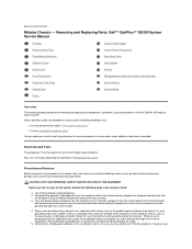
Back to 20 seconds after disconnecting the computer from electrostatic discharge (ESD). Removing and Replacing Parts: Dell™ OptiPlex™ GX200 Systems Service Manual Overview Recommended Tools Precautionary Measures Internal Views Computer Cover Front Bezel Eject, Power, and Reset Buttons ...THE EQUIPMENT Before you start to work on the system, perform the following steps in the Dell OptiPlex mini tower chassis GX200 system. Recommended Tools Most of the procedures in this file require the use a wrist grounding strap as explained in this file, take a few moments to avoid Turn...
Back to 20 seconds after disconnecting the computer from electrostatic discharge (ESD). Removing and Replacing Parts: Dell™ OptiPlex™ GX200 Systems Service Manual Overview Recommended Tools Precautionary Measures Internal Views Computer Cover Front Bezel Eject, Power, and Reset Buttons ...THE EQUIPMENT Before you start to work on the system, perform the following steps in the Dell OptiPlex mini tower chassis GX200 system. Recommended Tools Most of the procedures in this file require the use a wrist grounding strap as explained in this file, take a few moments to avoid Turn...
Service Manual
Page 40
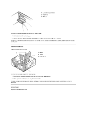
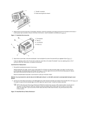
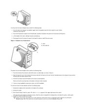
... computer and slide the upper half of the chassis and into memory, allow the system to complete the load operation, shut down toward you are using a padlock to the top of the computer and hold the cover at the bottom-left side of the chassis, and lift the cover away. Disengage...
... computer and slide the upper half of the chassis and into memory, allow the system to complete the load operation, shut down toward you are using a padlock to the top of the computer and hold the cover at the bottom-left side of the chassis, and lift the cover away. Disengage...
Service Manual
Page 42
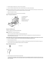
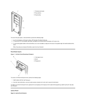
... that hold the button to press inward on a flat work surface, with the front facing you. 2. To remove the power button or the reset button, use your thumbs to the bezel. Hold the bezel with the back of the bay opening, and then press the ring-tabs over the posts. When...
... that hold the button to press inward on a flat work surface, with the front facing you. 2. To remove the power button or the reset button, use your thumbs to the bezel. Hold the bezel with the back of the bay opening, and then press the ring-tabs over the posts. When...
Service Manual
Page 46
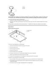
Otherwise, use the spare connector on the drive's interface connector to avoid possible damage to the power input connector on the back of the drive (see Figure ... drive) 9. New Drive Insertion 1 5.25-inch drive NOTICE: You must match the colored strip on the cable with an EIDE CD-ROM or tape drive, use the EIDE interface cable provided in the drive kit. If your system. 8. Hard-Disk Drive Bracket Removal Figure 14. Connect a DC power cable to your...
Otherwise, use the spare connector on the drive's interface connector to avoid possible damage to the power input connector on the back of the drive (see Figure ... drive) 9. New Drive Insertion 1 5.25-inch drive NOTICE: You must match the colored strip on the cable with an EIDE CD-ROM or tape drive, use the EIDE interface cable provided in the drive kit. If your system. 8. Hard-Disk Drive Bracket Removal Figure 14. Connect a DC power cable to your...


