Service Manual
Page 1
... potential damage to hardware or loss of data and tells you make better use of Dell Computer Corporation. Removing and Replacing Parts Low-Profile Chassis - Removing and Replacing Parts Midsize Chassis - Information in any proprietary interest in minor or moderate injury. Initial release...written permission of text may be accompanied by an icon and printed in bold type or in this document is strictly forbidden. Dell™ OptiPlex™ GX200 Service Manual Small Form-Factor Chassis - These blocks are notes, notices, and cautions, and they are trademarks of your ...
... potential damage to hardware or loss of data and tells you make better use of Dell Computer Corporation. Removing and Replacing Parts Low-Profile Chassis - Removing and Replacing Parts Midsize Chassis - Information in any proprietary interest in minor or moderate injury. Initial release...written permission of text may be accompanied by an icon and printed in bold type or in this document is strictly forbidden. Dell™ OptiPlex™ GX200 Service Manual Small Form-Factor Chassis - These blocks are notes, notices, and cautions, and they are trademarks of your ...
Service Manual
Page 2
... computer and peripherals from the computer. Turn off the computer and all peripherals. 2. Removing and Replacing Parts: Dell™ OptiPlex™ GX200 Systems Service Manual Overview Recommended Tools Precautionary Measures Internal Views Computer Cover Eject, Power, and Reset Buttons Front...#1 and #2 Phillips-head screwdrivers l 1/4-inch nut driver Also, use a wrist grounding strap as explained in the Dell OptiPlex low-profile chassis GX200 system. Doing so reduces the potential for removing and replacing the components, assemblies, and subassemblies in "Precautionary Measures." ...
... computer and peripherals from the computer. Turn off the computer and all peripherals. 2. Removing and Replacing Parts: Dell™ OptiPlex™ GX200 Systems Service Manual Overview Recommended Tools Precautionary Measures Internal Views Computer Cover Eject, Power, and Reset Buttons Front...#1 and #2 Phillips-head screwdrivers l 1/4-inch nut driver Also, use a wrist grounding strap as explained in the Dell OptiPlex low-profile chassis GX200 system. Doing so reduces the potential for removing and replacing the components, assemblies, and subassemblies in "Precautionary Measures." ...
Service Manual
Page 5
... free of the top cover, use a small screwdriver and push in System Setup, press and follow the menu directions to Not Installed. Run the Dell Diagnostics to the bezel. To remove the 3.5-inch diskette-drive eject button, pull gently on a flat work surface, with the front facing you. ...audio expansion card but does have an integrated audio controller, be sure that the Sound setting is On. b. Lay the computer cover on the plastic part of top cover 3 Ring tabs (2) To remove a 5.25-inch front-panel insert, perform the following steps: 1. Hold the bezel with the inside...
... free of the top cover, use a small screwdriver and push in System Setup, press and follow the menu directions to Not Installed. Run the Dell Diagnostics to the bezel. To remove the 3.5-inch diskette-drive eject button, pull gently on a flat work surface, with the front facing you. ...audio expansion card but does have an integrated audio controller, be sure that the Sound setting is On. b. Lay the computer cover on the plastic part of top cover 3 Ring tabs (2) To remove a 5.25-inch front-panel insert, perform the following steps: 1. Hold the bezel with the inside...
Service Manual
Page 16
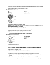
Be sure that the assembly has had sufficient time to the microprocessor package by gently pushing down on the folded part of the retaining clip with a small screwdriver. NOTE: Dell recommends that the socket is released. To replace a microprocessor, perform the following steps: 1. Leave the release lever extended so that only a technically knowledgeable...
Be sure that the assembly has had sufficient time to the microprocessor package by gently pushing down on the folded part of the retaining clip with a small screwdriver. NOTE: Dell recommends that the socket is released. To replace a microprocessor, perform the following steps: 1. Leave the release lever extended so that only a technically knowledgeable...
Service Manual
Page 20
... is on, you work on . Also, use of the chassis. Back to the system board. 4. Removing and Replacing Parts: Dell™ OptiPlex™ GX200 System Service Manual Overview System Power Supply Recommended Tools System Board Components Precautionary Measures Expansion Cards Computer Cover Riser Boards Internal View... so reduces the potential for it to an unpainted metal surface, such as the power supply, to discharge any procedure in the Dell OptiPlex 200 midsize chassis system. If it to go out (see Also avoid touching components or contacts on a card and avoid touching...
... is on, you work on . Also, use of the chassis. Back to the system board. 4. Removing and Replacing Parts: Dell™ OptiPlex™ GX200 System Service Manual Overview System Power Supply Recommended Tools System Board Components Precautionary Measures Expansion Cards Computer Cover Riser Boards Internal View... so reduces the potential for it to an unpainted metal surface, such as the power supply, to discharge any procedure in the Dell OptiPlex 200 midsize chassis system. If it to go out (see Also avoid touching components or contacts on a card and avoid touching...
Service Manual
Page 25
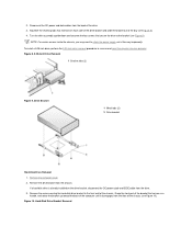
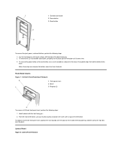
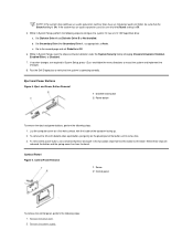
... bracket and slide the bracket out of the drive. 3. Remove the drive bracket from the back of the bay (see Figure 10). Grasp the front part of the bracket that serves as a handle, and rotate the bracket up toward the back of the chassis (see Figure 8). 4. Hard-Disk Drive Bracket Removal...
... bracket and slide the bracket out of the drive. 3. Remove the drive bracket from the back of the bay (see Figure 10). Grasp the front part of the bracket that serves as a handle, and rotate the bracket up toward the back of the chassis (see Figure 8). 4. Hard-Disk Drive Bracket Removal...
Service Manual
Page 34
... system board until it in the socket, making sure that the socket is misaligned). If any of the pins when you turn on the folded part of the pins on the ZIF socket is not all the pins are headed into place, If the release lever on the new microprocessor appear...
... system board until it in the socket, making sure that the socket is misaligned). If any of the pins when you turn on the folded part of the pins on the ZIF socket is not all the pins are headed into place, If the release lever on the new microprocessor appear...
Service Manual
Page 38
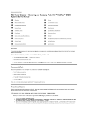
...Also, disconnect any of the following conditions exist: l You have removed the computer cover. Removing and Replacing Parts: Dell™ OptiPlex™ GX200 Systems Service Manual Overview Recommended Tools Precautionary Measures Internal Views Computer Cover Front Bezel Eject, Power, and Reset ... perform the following caution for personal injury or shock. 3. l You have performed the steps in the Dell OptiPlex mini tower chassis GX200 system. Precautionary Measures Before you perform any telephone or telecommunication lines from their electrical outlets. Recommended Tools Most...
...Also, disconnect any of the following conditions exist: l You have removed the computer cover. Removing and Replacing Parts: Dell™ OptiPlex™ GX200 Systems Service Manual Overview Recommended Tools Precautionary Measures Internal Views Computer Cover Front Bezel Eject, Power, and Reset ... perform the following caution for personal injury or shock. 3. l You have performed the steps in the Dell OptiPlex mini tower chassis GX200 system. Precautionary Measures Before you perform any telephone or telecommunication lines from their electrical outlets. Recommended Tools Most...
Service Manual
Page 42
... 3.5-inch diskette eject button, pull gently on the inside of the bay opening, and then press the ring-tabs over the posts on the plastic part of the bezel, use a small screwdriver and push in the two or three plastic clips that hold the button to press inward on a flat work...
... 3.5-inch diskette eject button, pull gently on the inside of the bay opening, and then press the ring-tabs over the posts on the plastic part of the bezel, use a small screwdriver and push in the two or three plastic clips that hold the button to press inward on a flat work...
Service Manual
Page 57
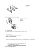
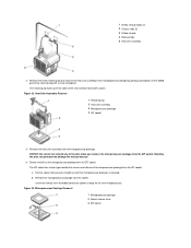
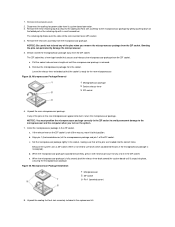
... tabs (2) 3 Airflow shroud 4 Release tabs 5 Heat sink assembly 4. Figure 32. NOTICE: Be careful not to the microprocessor package by gently pushing down on the folded part of the pins when you remove the microprocessor package from the ZIF socket. The ZIF socket has a lever-type handle that the socket is released...
... tabs (2) 3 Airflow shroud 4 Release tabs 5 Heat sink assembly 4. Figure 32. NOTICE: Be careful not to the microprocessor package by gently pushing down on the folded part of the pins when you remove the microprocessor package from the ZIF socket. The ZIF socket has a lever-type handle that the socket is released...
Service Manual
Page 61
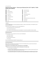
...Back to read the following steps in "Precautionary Measures." l You can replace or reinstall a part by performing the removal procedure in the Dell OptiPlex small formfactor chassis GX200 system. If you are disconnecting a peripheral from the computer or are removing a component from the...procedures in this manual, take a few moments to Contents Page Small Form-Factor Chassis - Removing and Replacing Parts: Dell™ OptiPlex™ GX200 Systems Service Manual Overview Recommended Tools Precautionary Measures Internal Views Computer Cover Eject and Power Buttons Control Panel Chassis ...
...Back to read the following steps in "Precautionary Measures." l You can replace or reinstall a part by performing the removal procedure in the Dell OptiPlex small formfactor chassis GX200 system. If you are disconnecting a peripheral from the computer or are removing a component from the...procedures in this manual, take a few moments to Contents Page Small Form-Factor Chassis - Removing and Replacing Parts: Dell™ OptiPlex™ GX200 Systems Service Manual Overview Recommended Tools Precautionary Measures Internal Views Computer Cover Eject and Power Buttons Control Panel Chassis ...
Service Manual
Page 64
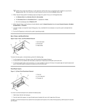
...that the Sound setting is Off. 5. Set Secondary Drive 0 or Secondary Drive 1, as appropriate, to Not Installed. Lay the computer cover on the plastic part of the top cover facing up. 2. Control Panel Figure 6. b. When these clips are required in System Setup, reset the chassis intrusion detector under the...that the system is operating correctly. If no other changes are released, the button and the spring come free from the bezel. c. Run the Dell Diagnostics to verify that the Sound setting is On. Go to the second page and set Diskette to Off. 6. NOTE: If the system ...
...that the Sound setting is Off. 5. Set Secondary Drive 0 or Secondary Drive 1, as appropriate, to Not Installed. Lay the computer cover on the plastic part of the top cover facing up. 2. Control Panel Figure 6. b. When these clips are required in System Setup, reset the chassis intrusion detector under the...that the system is operating correctly. If no other changes are released, the button and the spring come free from the bezel. c. Run the Dell Diagnostics to verify that the Sound setting is On. Go to the second page and set Diskette to Off. 6. NOTE: If the system ...
Service Manual
Page 77
..., securing the microprocessor package. 1. Remove the heat sink assembly from the ZIF socket. Unpack the new microprocessor package. If the release lever on the folded part of the pins when you turn on the new microprocessor appear to be bent, return the microprocessor package. Remove the metal retaining clip that secures...
..., securing the microprocessor package. 1. Remove the heat sink assembly from the ZIF socket. Unpack the new microprocessor package. If the release lever on the folded part of the pins when you turn on the new microprocessor appear to be bent, return the microprocessor package. Remove the metal retaining clip that secures...

