Service Manual
Page 8
... OptiPlex NX1 Computer 2-9 Internal View of the Low-Profile Computer 4-3 Computer Cover Removal 4-3 Eject, Power, and Reset Button Removal 4-4 Front-Panel Insert Removal 4-5 Control Panel Removal 4-6 Drive Hardware 4-7 3.5-Inch Diskette Drive Removal 4-8 5.25-Inch Drive Assembly Removal 4-9 Hard-Disk Drive Assembly Removal 4-10 System Power-Supply Removal 4-11 Expansion-Card Cage Removal 4-12 Expansion-Card Removal 4-13 Riser Board Removal 4-14 System Board Removal...
... OptiPlex NX1 Computer 2-9 Internal View of the Low-Profile Computer 4-3 Computer Cover Removal 4-3 Eject, Power, and Reset Button Removal 4-4 Front-Panel Insert Removal 4-5 Control Panel Removal 4-6 Drive Hardware 4-7 3.5-Inch Diskette Drive Removal 4-8 5.25-Inch Drive Assembly Removal 4-9 Hard-Disk Drive Assembly Removal 4-10 System Power-Supply Removal 4-11 Expansion-Card Cage Removal 4-12 Expansion-Card Removal 4-13 Riser Board Removal 4-14 System Board Removal...
Service Manual
Page 9
...-Stand Removal 5-4 Computer Cover Removal 5-5 Eject, Power, and Reset Button Removal 5-6 Front-Panel Insert Removal 5-7 Control Panel Removal 5-8 Drive Hardware 5-9 3.5-Inch Diskette Drive Removal 5-10 5.25-Inch Drive Assembly Removal 5-11 5.25-Inch Drive Removal 5-11 Hard-Disk Drive Bracket Removal 5-12 Hard-Disk Drive Removal 5-13 System Power-Supply Removal 5-14 Expansion-Card Cage Removal 5-15 Expansion-Card Removal 5-16 Riser Board Removal 5-17...
...-Stand Removal 5-4 Computer Cover Removal 5-5 Eject, Power, and Reset Button Removal 5-6 Front-Panel Insert Removal 5-7 Control Panel Removal 5-8 Drive Hardware 5-9 3.5-Inch Diskette Drive Removal 5-10 5.25-Inch Drive Assembly Removal 5-11 5.25-Inch Drive Removal 5-11 Hard-Disk Drive Bracket Removal 5-12 Hard-Disk Drive Removal 5-13 System Power-Supply Removal 5-14 Expansion-Card Cage Removal 5-15 Expansion-Card Removal 5-16 Riser Board Removal 5-17...
Service Manual
Page 10
... System Battery Installation 6-25 Internal View of the OptiPlex NX1 Computer 7-3 Optional-Stand Removal 7-3 Computer Cover Removal 7-4 Service Access Lock 7-5 Control Panel Removal 7-6 Hard-Disk Drive Removal 7-7 System Power-Supply Removal 7-8 Expansion-Card Cage Removal 7-9 Expansion-Card Removal 7-10 Riser Board Removal 7-11 System Board Removal 7-12 System Board Components 7-13 DIMM Removal 7-14 DIMM Installation 7-14 Installing a Video-Memory Upgrade Module...
... System Battery Installation 6-25 Internal View of the OptiPlex NX1 Computer 7-3 Optional-Stand Removal 7-3 Computer Cover Removal 7-4 Service Access Lock 7-5 Control Panel Removal 7-6 Hard-Disk Drive Removal 7-7 System Power-Supply Removal 7-8 Expansion-Card Cage Removal 7-9 Expansion-Card Removal 7-10 Riser Board Removal 7-11 System Board Removal 7-12 System Board Components 7-13 DIMM Removal 7-14 DIMM Installation 7-14 Installing a Video-Memory Upgrade Module...
Service Manual
Page 18
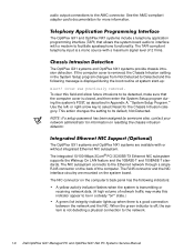
...Wakeup On LAN feature and the 10BASE-T and 100BASE-T standards. audio output connections to its default, Not Detected. If the computer cover is removed, the Chassis Intrusion setting in the System Setup program changes from Not Detected to the network. 1-6 When the green indicator is ...the system is a mono source with a maximum signal level of the computer. The OptiPlex GX1 systems and OptiPlex NX1 systems are mounted on the back of 2 Vrms. The OptiPlex GX1 systems and OptiPlex NX1 systems provide chassis intrusion detection. or right-arrow key to the Ethernet network through ...
...Wakeup On LAN feature and the 10BASE-T and 100BASE-T standards. audio output connections to its default, Not Detected. If the computer cover is removed, the Chassis Intrusion setting in the System Setup program changes from Not Detected to the network. 1-6 When the green indicator is ...the system is a mono source with a maximum signal level of the computer. The OptiPlex GX1 systems and OptiPlex NX1 systems are mounted on the back of 2 Vrms. The OptiPlex GX1 systems and OptiPlex NX1 systems provide chassis intrusion detection. or right-arrow key to the Ethernet network through ...

Service Manual
Page 60
... hard-disk drive. Verify the correct operation of the video controller and the video control circuitry Keyboard Tests - Starting the diagnostics causes the Dell logo to isolate a failure Run All Tests - Tests a particular area or subsystem If the Diagnostics Menu does not appear, check with ...the Diagnostics Menu appears. Checks the functionality of the mouse controller and the operation of the following options or exit to remove the computer cover, see "Getting Help" found later in this chapter. Otherwise, see "Internal Visual Inspection" found earlier in this chapter.
... hard-disk drive. Verify the correct operation of the video controller and the video control circuitry Keyboard Tests - Starting the diagnostics causes the Dell logo to isolate a failure Run All Tests - Tests a particular area or subsystem If the Diagnostics Menu does not appear, check with ...the Diagnostics Menu appears. Checks the functionality of the mouse controller and the operation of the following options or exit to remove the computer cover, see "Getting Help" found later in this chapter. Otherwise, see "Internal Visual Inspection" found earlier in this chapter.

Service Manual
Page 73
Before you are servicing a midsize, mini tower, or OptiPlex NX1 Net PC chassis, use of one or more of the following : You have removed the computer cover. Unless otherwise noted, each procedure assumes the following tools: Small flat-blade screwdriver Wide flat-blade screwdriver #1 ...is provided. You can replace or reinstall a part by performing the removal procedure in the next section, "Precautionary Measures." You have performed the steps in "Precautionary Measures" found later in the Dell OptiPlex GX1 low-profile computer. This chapter provides procedures for your system. ...
Before you are servicing a midsize, mini tower, or OptiPlex NX1 Net PC chassis, use of one or more of the following : You have removed the computer cover. Unless otherwise noted, each procedure assumes the following tools: Small flat-blade screwdriver Wide flat-blade screwdriver #1 ...is provided. You can replace or reinstall a part by performing the removal procedure in the next section, "Precautionary Measures." You have performed the steps in "Precautionary Measures" found later in the Dell OptiPlex GX1 low-profile computer. This chapter provides procedures for your system. ...

Service Manual
Page 76
computer cover (upside down) eject button reset button power button 4-4 To remove the computer cover, follow these steps: Three plastic hooks on the inside the computer. Before you reinstall the cover, fold all cables out of the way so that they do not interfere with the cover or with proper airflow inside -front part of the cover secure it to the chassis.
computer cover (upside down) eject button reset button power button 4-4 To remove the computer cover, follow these steps: Three plastic hooks on the inside the computer. Before you reinstall the cover, fold all cables out of the way so that they do not interfere with the cover or with proper airflow inside -front part of the cover secure it to the chassis.

Service Manual
Page 77
computer cover (upside down) 5.25-inch front-panel insert posts (2) ring-tabs (2) To remove a front-panel insert, follow these clips are released, the button comes free from the front panel of the bay opening, and then press the ring-tabs over the posts on the inside of the cover. Removing and Replacing Parts on the ring-tabs. If necessary, use a 1/4-inch nutdriver to help push on the Low-Profile Chassis 4-5 When these steps: To replace a 5.25-inch front-panel insert, position the two ring-tabs over the posts.
computer cover (upside down) 5.25-inch front-panel insert posts (2) ring-tabs (2) To remove a front-panel insert, follow these clips are released, the button comes free from the front panel of the bay opening, and then press the ring-tabs over the posts on the inside of the cover. Removing and Replacing Parts on the ring-tabs. If necessary, use a 1/4-inch nutdriver to help push on the Low-Profile Chassis 4-5 When these steps: To replace a 5.25-inch front-panel insert, position the two ring-tabs over the posts.

Service Manual
Page 81
...: When you replace the 5.25-inch drive, place the front of the drive toward the front of the computer cover around the 5.25-inch drive bezel. Check the alignment of the bracket; Removing and Replacing Parts on the bracket to align it. Adjust the drive forward or backward on the Low-Profile...
...: When you replace the 5.25-inch drive, place the front of the drive toward the front of the computer cover around the 5.25-inch drive bezel. Check the alignment of the bracket; Removing and Replacing Parts on the bracket to align it. Adjust the drive forward or backward on the Low-Profile...

Service Manual
Page 95
... the removal procedure in the Dell OptiPlex GX1 midsize computer. This chapter provides procedures for your personal safety and to prevent damage to read the following warning for your system. You have performed the steps in "Precautionary Measures" found later in this chapter. Removing and.... If you perform any of the procedures in the next section, "Precautionary Measures." Most of the following : You have removed the computer cover. Unless otherwise noted, each procedure assumes the following tools: Small flat-blade screwdriver Wide flat-blade screwdriver #1 and #2 Phillips...
... the removal procedure in the Dell OptiPlex GX1 midsize computer. This chapter provides procedures for your personal safety and to prevent damage to read the following warning for your system. You have performed the steps in "Precautionary Measures" found later in this chapter. Removing and.... If you perform any of the procedures in the next section, "Precautionary Measures." Most of the following : You have removed the computer cover. Unless otherwise noted, each procedure assumes the following tools: Small flat-blade screwdriver Wide flat-blade screwdriver #1 and #2 Phillips...

Service Manual
Page 99
securing buttons (2) front of the cover secure it to the chassis. Before you reinstall the cover, fold all cables out of the way so that they do not interfere with the cover or with proper airflow inside -front part of computer To remove the computer cover, follow these steps: Four plastic hooks on the Midsize Chassis 5-5 Removing and Replacing Parts on the inside the computer.
securing buttons (2) front of the cover secure it to the chassis. Before you reinstall the cover, fold all cables out of the way so that they do not interfere with the cover or with proper airflow inside -front part of computer To remove the computer cover, follow these steps: Four plastic hooks on the Midsize Chassis 5-5 Removing and Replacing Parts on the inside the computer.

Service Manual
Page 100
eject button computer cover (upside down) reset button power button To remove the eject, power, and reset buttons, follow these steps: When these clips are released, the button comes free from the front panel of the cover. 5-6
eject button computer cover (upside down) reset button power button To remove the eject, power, and reset buttons, follow these steps: When these clips are released, the button comes free from the front panel of the cover. 5-6

Service Manual
Page 101
Removing and Replacing Parts on the inside of the bay opening, and then press the ring-tabs over the posts on the Midsize Chassis 5-7 computer cover (upside down) 5.25-inch front-panel insert posts (2) ring-tabs (2) To remove a front-panel insert, follow these steps: To replace a 5.25-inch front-panel insert, position the two ring-tabs over the posts. If necessary, use a 1/4-inch nutdriver to help push on the ring-tabs.
Removing and Replacing Parts on the inside of the bay opening, and then press the ring-tabs over the posts on the Midsize Chassis 5-7 computer cover (upside down) 5.25-inch front-panel insert posts (2) ring-tabs (2) To remove a front-panel insert, follow these steps: To replace a 5.25-inch front-panel insert, position the two ring-tabs over the posts. If necessary, use a 1/4-inch nutdriver to help push on the ring-tabs.

Service Manual
Page 119
... damage to the system from ESD. You can replace or reinstall a part by performing the removal procedure in the Dell OptiPlex GX1 mini tower computer. If you perform any of the following tools: Small flat-blade screwdriver... Wide flat-blade screwdriver #1 and #2 Phillips screwdrivers 1/4-inch nutdriver Tweezers or long-nose pliers Also, use Chapter 4, 5, or 7, as explained in this chapter, take a few moments to read the following : You have removed the computer cover...
... damage to the system from ESD. You can replace or reinstall a part by performing the removal procedure in the Dell OptiPlex GX1 mini tower computer. If you perform any of the following tools: Small flat-blade screwdriver... Wide flat-blade screwdriver #1 and #2 Phillips screwdrivers 1/4-inch nutdriver Tweezers or long-nose pliers Also, use Chapter 4, 5, or 7, as explained in this chapter, take a few moments to read the following : You have removed the computer cover...

Service Manual
Page 122
To remove the computer cover, follow these steps: release button Before you reinstall the cover, fold all cables out of the way so that they do not interfere with the cover or with proper airflow inside the computer. 6-4
To remove the computer cover, follow these steps: release button Before you reinstall the cover, fold all cables out of the way so that they do not interfere with the cover or with proper airflow inside the computer. 6-4

Service Manual
Page 145
You have performed the steps in "Precautionary Measures" found later in this chapter. Removing and Replacing Parts on the OptiPlex NX1 Net PC Chassis 7-1 Unless otherwise noted, each procedure assumes the following tools: Small...and subassemblies in reverse order unless additional information is provided. You can replace or reinstall a part by performing the removal procedure in the Dell OptiPlex NX1 Net PC computer. Most of the procedures in this chapter require the use Chapter 4, 5, or 6, as... from ESD. If you perform any of the following : You have removed the computer cover.
You have performed the steps in "Precautionary Measures" found later in this chapter. Removing and Replacing Parts on the OptiPlex NX1 Net PC Chassis 7-1 Unless otherwise noted, each procedure assumes the following tools: Small...and subassemblies in reverse order unless additional information is provided. You can replace or reinstall a part by performing the removal procedure in the Dell OptiPlex NX1 Net PC computer. Most of the procedures in this chapter require the use Chapter 4, 5, or 6, as... from ESD. If you perform any of the following : You have removed the computer cover.

Service Manual
Page 149
You may have to the chassis. Removing and Replacing Parts on the back edge of the way so that they do not interfere with the cover or with proper airflow inside the computer. To remove the computer cover, follow these steps: security cable slot padlock ring service access lock Four plastic hooks at the front of the cover secure it to press gently downward on the OptiPlex NX1 Net PC Chassis 7-5 Before you reinstall the cover, fold all cables out of the cover while engaging the locking mechanism.
You may have to the chassis. Removing and Replacing Parts on the back edge of the way so that they do not interfere with the cover or with proper airflow inside the computer. To remove the computer cover, follow these steps: security cable slot padlock ring service access lock Four plastic hooks at the front of the cover secure it to press gently downward on the OptiPlex NX1 Net PC Chassis 7-5 Before you reinstall the cover, fold all cables out of the cover while engaging the locking mechanism.

Service Manual
Page 167
... Keyboard Errors System Password Password Status Boot Sequence Setup Password Auto Power On Power Management Displays the status of system's password security feature. If computer cover is removed, the setting changes from Detected to power on automatically. or right-arrow key to assign and verify a new password. Restricts access to Not Detected...
... Keyboard Errors System Password Password Status Boot Sequence Setup Password Auto Power On Power Management Displays the status of system's password security feature. If computer cover is removed, the setting changes from Detected to power on automatically. or right-arrow key to assign and verify a new password. Restricts access to Not Detected...
Service Manual
Page 172
...) components, illustrated, low-profile computer, 1-9 components, illustrated, midsize computer, 1-10 components, illustrated, mini tower computer, 1-11 components, illustrated, OptiPlex NX1 computer, 1-12 controls and indicators, 1-7 cover removal, low-profile computer, 4-3 cover removal, midsize computer, 5-5 cover removal, mini tower computer, 6-4 cover removal, OptiPlex NX1 computer, 7-4 diagnostics. See diagnostics DMA channel assignments, 1-20 expansion features, 1-12 features, 1-1, 1-3 front-panel views, 1-8 internal views...
...) components, illustrated, low-profile computer, 1-9 components, illustrated, midsize computer, 1-10 components, illustrated, mini tower computer, 1-11 components, illustrated, OptiPlex NX1 computer, 1-12 controls and indicators, 1-7 cover removal, low-profile computer, 4-3 cover removal, midsize computer, 5-5 cover removal, mini tower computer, 6-4 cover removal, OptiPlex NX1 computer, 7-4 diagnostics. See diagnostics DMA channel assignments, 1-20 expansion features, 1-12 features, 1-1, 1-3 front-panel views, 1-8 internal views...


