Setup and Features Information Tech Sheet
Page 6
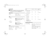
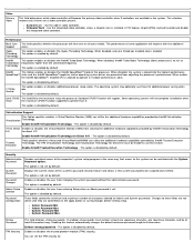
...Form Factor one one (slimline) one two one one (slimline) Control Lights and Diagnostic Lights Front of the computer. System Information Chipset Processor Intel® Q57 chipset Intel Core™ i3/i5/i7 series Intel Pentium® dual-core Video Video type: Integrated Discrete Video ...memory: Integrated Intel Graphics Media Accelerator HD NOTE: Not supported by law to support.dell.com. Blinking amber light - Solid amber light (when the computer does not start) - PCI-E x16 graphics card Upto 1759 MB (shared...
...Form Factor one one (slimline) one two one one (slimline) Control Lights and Diagnostic Lights Front of the computer. System Information Chipset Processor Intel® Q57 chipset Intel Core™ i3/i5/i7 series Intel Pentium® dual-core Video Video type: Integrated Discrete Video ...memory: Integrated Intel Graphics Media Accelerator HD NOTE: Not supported by law to support.dell.com. Blinking amber light - Solid amber light (when the computer does not start) - PCI-E x16 graphics card Upto 1759 MB (shared...
Technical Guidebook
Page 2
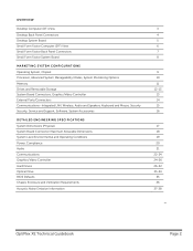
... System Board Small Form Factor Computer (SFF) View Small Form Factor Back Panel Connectors Small Form Factor System Board MARKETING SYSTEM CONFIGURATIONS Operating System, Chipset Processor, Advanced System Manageability Modes, System Monitoring Options Memory Drives and Removable Storage System Board Connectors, Graphics/Video Controller External Ports/Connectors Communications-Integrated LAN, Wireless... 3 4 5 6 7 8 9 10 11 12-13 13 14 15 16 17 18 19 20 21 22-24 24-26 26-32 33-34 35 36 37-38 OptiPlex XE Technical Guidebook Page 2
... System Board Small Form Factor Computer (SFF) View Small Form Factor Back Panel Connectors Small Form Factor System Board MARKETING SYSTEM CONFIGURATIONS Operating System, Chipset Processor, Advanced System Manageability Modes, System Monitoring Options Memory Drives and Removable Storage System Board Connectors, Graphics/Video Controller External Ports/Connectors Communications-Integrated LAN, Wireless... 3 4 5 6 7 8 9 10 11 12-13 13 14 15 16 17 18 19 20 21 22-24 24-26 26-32 33-34 35 36 37-38 OptiPlex XE Technical Guidebook Page 2
Technical Guidebook
Page 5
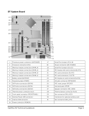
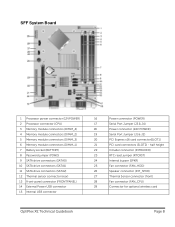
DT System Board 1 Processor power connector (12VPOWER) 2 Processor connector (CPU) 3 Memory module connectors (DIMM_4) 4 Memory module connectors (DIMM_2) 5 Memory module connectors (DIMM_3) 6 Memory module connectors (DIMM_1) 7 Battery socket (BATTERY) 8 Password jumper (PSWD)... (SATA2) 12 Thermal sensor connector (rear) 13 Front-panel connector (FRONTPANEL) 14 External Power USB connector 15 Internal USB connector 16 Power connector (POWER) OptiPlex XE Technical Guidebook 17 Serial Port Jumper (J3 & J4) 18 Power connector (24V POWER) 19 Serial Port Jumper (J1 & J2) 20 PCI Express ...
DT System Board 1 Processor power connector (12VPOWER) 2 Processor connector (CPU) 3 Memory module connectors (DIMM_4) 4 Memory module connectors (DIMM_2) 5 Memory module connectors (DIMM_3) 6 Memory module connectors (DIMM_1) 7 Battery socket (BATTERY) 8 Password jumper (PSWD)... (SATA2) 12 Thermal sensor connector (rear) 13 Front-panel connector (FRONTPANEL) 14 External Power USB connector 15 Internal USB connector 16 Power connector (POWER) OptiPlex XE Technical Guidebook 17 Serial Port Jumper (J3 & J4) 18 Power connector (24V POWER) 19 Serial Port Jumper (J1 & J2) 20 PCI Express ...
Technical Guidebook
Page 8
... (FAN_HDD) 26 Speaker connector (INT_SPKR) 27 Thermal Sensor connector (front) 28 Fan connector (FAN_CPU) 29 Connector for optional wireless card OptiPlex XE Technical Guidebook Page 8 SFF System Board 1 Processor power connector (12VPOWER) 2 Processor connector (CPU) 3 Memory module connectors (DIMM_4) 4 Memory module connectors (DIMM_2) 5 Memory module connectors (DIMM_3) 6 Memory module connectors (DIMM_1) 7 Battery socket...
... (FAN_HDD) 26 Speaker connector (INT_SPKR) 27 Thermal Sensor connector (front) 28 Fan connector (FAN_CPU) 29 Connector for optional wireless card OptiPlex XE Technical Guidebook Page 8 SFF System Board 1 Processor power connector (12VPOWER) 2 Processor connector (CPU) 3 Memory module connectors (DIMM_4) 4 Memory module connectors (DIMM_2) 5 Memory module connectors (DIMM_3) 6 Memory module connectors (DIMM_1) 7 Battery socket...
Technical Guidebook
Page 10
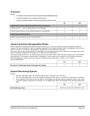
...; technology provides the capability to manage your enterprise. Processor NOTES: • The OptiPlex XE uses CPUs from Intel's long lifecycle Embedded Roadmap • Processor numbers are not a measure of performance. • Processor availability subject to change and may vary by region/...in hardware management capabilities across platform offerings. DT SFF Dell Watchdog Timer Optional via factory installation only OptiPlex XE Technical Guidebook Page 10 cannot be enabled through the Dell factory; Dell's innovative approach to scalable remote client management offers you...
...; technology provides the capability to manage your enterprise. Processor NOTES: • The OptiPlex XE uses CPUs from Intel's long lifecycle Embedded Roadmap • Processor numbers are not a measure of performance. • Processor availability subject to change and may vary by region/...in hardware management capabilities across platform offerings. DT SFF Dell Watchdog Timer Optional via factory installation only OptiPlex XE Technical Guidebook Page 10 cannot be enabled through the Dell factory; Dell's innovative approach to scalable remote client management offers you...
Technical Guidebook
Page 11
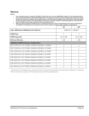
...the amount of memory available to the operating system is less than 4GB. To fully utilize 4GB or more of memory requires a 64-bit enabled processor and 64-bit operating system. If the memory modules are not installed in matched pairs, the computer will be less than 4GB. • The... entire 8GB memory range is available to operate, but with a slight reduction in performance. OptiPlex XE Technical Guidebook Page 11 however, 32-bit operating systems, such as the 32-bit version of Microsoft® Windows® XP, can only use...
...the amount of memory available to the operating system is less than 4GB. To fully utilize 4GB or more of memory requires a 64-bit enabled processor and 64-bit operating system. If the memory modules are not installed in matched pairs, the computer will be less than 4GB. • The... entire 8GB memory range is available to operate, but with a slight reduction in performance. OptiPlex XE Technical Guidebook Page 11 however, 32-bit operating systems, such as the 32-bit version of Microsoft® Windows® XP, can only use...
Technical Guidebook
Page 13
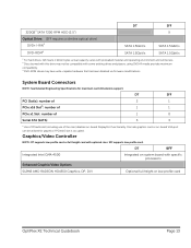
Graphics/Video Controller NOTE: DT supports low profile card or full height card with specific processors Enhanced Graphic/Video Options 512MB AMD RADEON HD4550 Graphics, DP, DVI Optional full height or low profile card OptiPlex XE Technical Guidebook Page 13 System Board Connectors NOTE: See Detailed Engineering Specifications for graphics if PCIex16 slot...
Graphics/Video Controller NOTE: DT supports low profile card or full height card with specific processors Enhanced Graphic/Video Options 512MB AMD RADEON HD4550 Graphics, DP, DVI Optional full height or low profile card OptiPlex XE Technical Guidebook Page 13 System Board Connectors NOTE: See Detailed Engineering Specifications for graphics if PCIex16 slot...
Technical Guidebook
Page 35
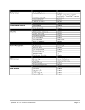
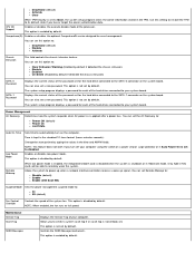
...: Service Tag: Asset Tag: SERR Message: Systems Management Fast Boot: Numlock LED: POST HotKeys: Keyboard Errors: Enable Disable, unless the customer purchased a SpeedStep™ capable processor. Enable Disable Enable Disable Not set Not set Enable Enable Deactivate Not set Power Off Disable Enable Disable S3 Disable Set by the factory Optional...
...: Service Tag: Asset Tag: SERR Message: Systems Management Fast Boot: Numlock LED: POST HotKeys: Keyboard Errors: Enable Disable, unless the customer purchased a SpeedStep™ capable processor. Enable Disable Enable Disable Not set Not set Enable Enable Deactivate Not set Power Off Disable Enable Disable S3 Disable Set by the factory Optional...
Service Manual
Page 2
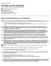
...To disconnect a network cable, first unplug the cable from your personal safety. Back to Contents Page Working on Your Computer Dell™ OptiPlex™ 980 Service Manual-Mini-Tower Before Working Inside Your Computer Recommended Tools Turning Off Your Computer After Working Inside Your Computer Before Working...to help to servicing that is not authorized by Dell is not covered by your warranty. Remove the cover. While you disconnect the cable. Unless otherwise noted, each procedure included in your product documentation, or as a processor by its edges, not by its pull-tab,...
...To disconnect a network cable, first unplug the cable from your personal safety. Back to Contents Page Working on Your Computer Dell™ OptiPlex™ 980 Service Manual-Mini-Tower Before Working Inside Your Computer Recommended Tools Turning Off Your Computer After Working Inside Your Computer Before Working...to help to servicing that is not authorized by Dell is not covered by your warranty. Remove the cover. While you disconnect the cable. Unless otherwise noted, each procedure included in your product documentation, or as a processor by its edges, not by its pull-tab,...

Service Manual
Page 4
...configuration of your computer, click Start® Help and Support and select the option to Contents Page Technical Specifications Processor Controls and Lights Memory Network Expansion Bus Audio Video Power System Information System Board Connectors Cards Physical Drives Environmental ...External Connectors NOTE: Offerings may vary by computers shipped with Intel i7 and Intel i5 quad-core processors. Processor Type Quad-Core Dual-Core Level 2 (L2) cache Intel Core i7 series Intel Core i5 series Intel Core...
...configuration of your computer, click Start® Help and Support and select the option to Contents Page Technical Specifications Processor Controls and Lights Memory Network Expansion Bus Audio Video Power System Information System Board Connectors Cards Physical Drives Environmental ...External Connectors NOTE: Offerings may vary by computers shipped with Intel i7 and Intel i5 quad-core processors. Processor Type Quad-Core Dual-Core Level 2 (L2) cache Intel Core i7 series Intel Core i5 series Intel Core...
Service Manual
Page 7
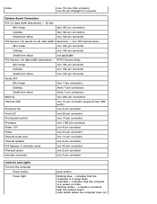
... 7-pin connectors Memory four 240-pin connectors Internal USB one 10-pin connector (supports two USB ports) Processor fan one 5-pin connector Front I/O one 26-pin connector Front panel control one 14-pin connector Processor one 1156-pin connector Power 12V one 4-pin connector Power one 24-pin connector Internal serial card...
... 7-pin connectors Memory four 240-pin connectors Internal USB one 10-pin connector (supports two USB ports) Processor fan one 5-pin connector Front I/O one 26-pin connector Front panel control one 14-pin connector Processor one 1156-pin connector Power 12V one 4-pin connector Power one 24-pin connector Internal serial card...

Service Manual
Page 11
Back to Contents Page Removing and Replacing Parts Dell™ OptiPlex™ 980 Service Manual-Mini-Tower Cover Drive Cover Optical Drive Hard Drive/Cage Front Panel Expansion Card Wireless Module Processor Fan Heat Sink and Processor Memory Module Internal Speaker Front Thermal Sensor Power Supply Control Panel Front I/O Panel Intrusion Switch Coin-Cell Battery System Board Back to Contents Page
Back to Contents Page Removing and Replacing Parts Dell™ OptiPlex™ 980 Service Manual-Mini-Tower Cover Drive Cover Optical Drive Hard Drive/Cage Front Panel Expansion Card Wireless Module Processor Fan Heat Sink and Processor Memory Module Internal Speaker Front Thermal Sensor Power Supply Control Panel Front I/O Panel Intrusion Switch Coin-Cell Battery System Board Back to Contents Page
Service Manual
Page 14
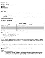
...Press to enter System Setup and make any changes to the boot order stored in the BIOS. Processor information: Displays the Processor Type, Processor Speed, Processor Bus Speed, Processor L2 cache, Processor ID, Using the boot menu does not make changes to navigate the System Setup screens. or ... Memory Speed, Number of Active Channels, Memory Technology, DIMM_1 Size, DIMM_2 Size. Back to Contents Page System Setup Dell™ OptiPlex™ 980 Service Manual-Desktop Boot Menu Navigation Keystrokes Entering System Setup System Setup Menu Options Boot Menu Press or when the...
...Press to enter System Setup and make any changes to the boot order stored in the BIOS. Processor information: Displays the Processor Type, Processor Speed, Processor Bus Speed, Processor L2 cache, Processor ID, Using the boot menu does not make changes to navigate the System Setup screens. or ... Memory Speed, Number of Active Channels, Memory Technology, DIMM_1 Size, DIMM_2 Size. Back to Contents Page System Setup Dell™ OptiPlex™ 980 Service Manual-Desktop Boot Menu Navigation Keystrokes Entering System Setup System Setup Menu Options Boot Menu Press or when the...
Service Manual
Page 16
...or disables the trusted platform module (TPM) security. Performance Multi Core Support HyperThreading Technology This field specifies whether the processor will improve with the System Password Password option. This option is enabled by Intel® Virtualization technology I/O for ... Virtualization Technology for additional power saving when idle. Auto(default) - C States Control This option enables or disables additional processor sleep states. Intel® Turbo Boost Technology This option enables or disables the Intel® Turbo Boost Technology. When ...
...or disables the trusted platform module (TPM) security. Performance Multi Core Support HyperThreading Technology This field specifies whether the processor will improve with the System Password Password option. This option is enabled by Intel® Virtualization technology I/O for ... Virtualization Technology for additional power saving when idle. Auto(default) - C States Control This option enables or disables additional processor sleep states. Intel® Turbo Boost Technology This option enables or disables the Intel® Turbo Boost Technology. When ...
Service Manual
Page 17
... On Last State Auto On Time Low Power Mode Remote Wakeup Sets time to : S1 S3 (default) Fan Control Override Controls the speed of the processor. Maintenance Service Tag Asset Tag SERR Messages Displays the Service Tag of the hard drives connected to disabled. You can also set a new password. NOTE...
... On Last State Auto On Time Low Power Mode Remote Wakeup Sets time to : S1 S3 (default) Fan Control Override Controls the speed of the processor. Maintenance Service Tag Asset Tag SERR Messages Displays the Service Tag of the hard drives connected to disabled. You can also set a new password. NOTE...
Service Manual
Page 24
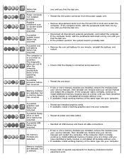
...one module (see your computer. Reseat the 2x2 power connector from the PCI and PCI-E slots and restart the computer. Reseat the processor. If the computer starts normally, continue to install additional memory modules (one . Reseat all internal and external peripherals, and restart the...see your service manual), then reinstall one . Possible peripheral card or system board failure has occurred. Remove all cable connections. A possible processor failure has occurred. failure has occurred. If the computer boots, add the peripheral cards back one by one until you find the bad...
...one module (see your computer. Reseat the 2x2 power connector from the PCI and PCI-E slots and restart the computer. Reseat the processor. If the computer starts normally, continue to install additional memory modules (one . Reseat all internal and external peripherals, and restart the...see your service manual), then reinstall one . Possible peripheral card or system board failure has occurred. Remove all cable connections. A possible processor failure has occurred. failure has occurred. If the computer boots, add the peripheral cards back one by one until you find the bad...
Service Manual
Page 49
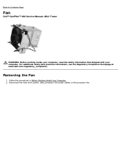
Follow the procedures in Before Working Inside Your Computer. 2. Disconnect the hard-drive power, data, processor-fan power cables on the processor fan. For additional safety best practices information, see the Regulatory Compliance Homepage at www.dell.com/regulatory_compliance. Removing the Fan 1. Back to Contents Page Fan Dell™ OptiPlex™ 980 Service Manual-Mini-Tower WARNING: Before working inside your computer, read the safety information that shipped with your computer.
Follow the procedures in Before Working Inside Your Computer. 2. Disconnect the hard-drive power, data, processor-fan power cables on the processor fan. For additional safety best practices information, see the Regulatory Compliance Homepage at www.dell.com/regulatory_compliance. Removing the Fan 1. Back to Contents Page Fan Dell™ OptiPlex™ 980 Service Manual-Mini-Tower WARNING: Before working inside your computer, read the safety information that shipped with your computer.

Service Manual
Page 50
3. Remove the screws from the system board. 4. Disconnect the fan connector from the processor fan shroud.
3. Remove the screws from the system board. 4. Disconnect the fan connector from the processor fan shroud.

Service Manual
Page 51
5. Replacing the Fan To replace the fan, perform the above steps in reverse order. Remove the processor fan from the heat sink. Back to Contents Page
5. Replacing the Fan To replace the fan, perform the above steps in reverse order. Remove the processor fan from the heat sink. Back to Contents Page
Service Manual
Page 52
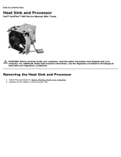
Follow the procedures in Before Working Inside Your Computer. 2. Release all the cables on the processor fan. Removing the Heat Sink and Processor 1. Back to Contents Page Heat Sink and Processor Dell™ OptiPlex™ 980 Service Manual-Mini-Tower WARNING: Before working inside your computer, read the safety information that shipped with your computer. For additional safety best practices information, see the Regulatory Compliance Homepage at www.dell.com/regulatory_compliance.
Follow the procedures in Before Working Inside Your Computer. 2. Release all the cables on the processor fan. Removing the Heat Sink and Processor 1. Back to Contents Page Heat Sink and Processor Dell™ OptiPlex™ 980 Service Manual-Mini-Tower WARNING: Before working inside your computer, read the safety information that shipped with your computer. For additional safety best practices information, see the Regulatory Compliance Homepage at www.dell.com/regulatory_compliance.


