
Setup and Quick Reference Guide
Page 7
About Your Computer Mini Tower - Front View 1 2 34 5 6 7 8 9 12 10 11 1 hard drive activity light 3 WiFi (optional) light 5 power button, power light 2 link integrity light 4 diagnostic lights 6 optical drive About Your Computer 7
About Your Computer Mini Tower - Front View 1 2 34 5 6 7 8 9 12 10 11 1 hard drive activity light 3 WiFi (optional) light 5 power button, power light 2 link integrity light 4 diagnostic lights 6 optical drive About Your Computer 7
Setup and Quick Reference Guide
Page 10
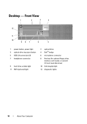
Desktop - Front View 1 2 3 4 12 11 10 987 6 5 1 power button, power light 3 optical-drive tray eject button 5 USB 2.0 connectors (2) 7 headphone connector 9 hard drive activity light 11 WiFi (optional) light 2 optical drive 4 Dell™ badge 6 microphone connector 8 flex bay (for optional floppy drive, memory card reader, or second 3.5-inch hard disk drive) 10 link integrity light 12 diagnostic lights 10 About Your Computer
Desktop - Front View 1 2 3 4 12 11 10 987 6 5 1 power button, power light 3 optical-drive tray eject button 5 USB 2.0 connectors (2) 7 headphone connector 9 hard drive activity light 11 WiFi (optional) light 2 optical drive 4 Dell™ badge 6 microphone connector 8 flex bay (for optional floppy drive, memory card reader, or second 3.5-inch hard disk drive) 10 link integrity light 12 diagnostic lights 10 About Your Computer
Setup and Quick Reference Guide
Page 13
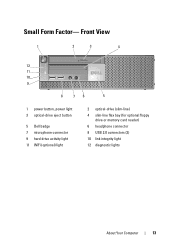
Small Form Factor- Front View 1 2 3 4 12 11 10 9 8 76 5 1 power button, power light 3 optical-drive eject button 5 Dell badge 7 microphone connector 9 hard drive activity light 11 WiFi (optional) light 2 optical-drive (slim-line) 4 slim-line flex bay (for optional floppy drive or memory card reader) 6 headphone connector 8 USB 2.0 connectors (2) 10 link integrity light 12 diagnostic lights About Your Computer 13
Small Form Factor- Front View 1 2 3 4 12 11 10 9 8 76 5 1 power button, power light 3 optical-drive eject button 5 Dell badge 7 microphone connector 9 hard drive activity light 11 WiFi (optional) light 2 optical-drive (slim-line) 4 slim-line flex bay (for optional floppy drive or memory card reader) 6 headphone connector 8 USB 2.0 connectors (2) 10 link integrity light 12 diagnostic lights About Your Computer 13
Setup and Quick Reference Guide
Page 34
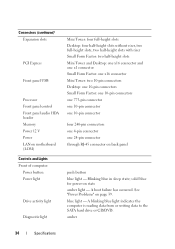
... panel USB Processor Front panel control Front panel audio HDA header Memory Power 12 V Power LAN on motherboard (LOM) Controls and Lights Front of computer: Power button Power light Drive activity light Diagnostic light Mini Tower: four full-height slots Desktop: four half-height slots without riser, two full-height slots, two half-height slots... one 10-pin connector four 240-pin connectors one 4-pin connector one 24-pin connector through RJ-45 connector on back panel push button blue light -
... panel USB Processor Front panel control Front panel audio HDA header Memory Power 12 V Power LAN on motherboard (LOM) Controls and Lights Front of computer: Power button Power light Drive activity light Diagnostic light Mini Tower: four full-height slots Desktop: four half-height slots without riser, two full-height slots, two half-height slots... one 10-pin connector four 240-pin connectors one 4-pin connector one 24-pin connector through RJ-45 connector on back panel push button blue light -

Setup and Quick Reference Guide
Page 39
...dell.com. Power Problems CAUTION: Before working inside your computer, read the safety information that best describes the problem and follow the remaining troubleshooting steps. This message may help support personnel to start the search. 3 In the search results, select the option that shipped with the system. The diagnostic lights...; If you added or removed a part before opening the cover. Consult the following table in a program, see www.dell.com/regulatory_compliance. Using the Hardware Troubleshooter 1 Click the Windows Vista Start button , and click Help and Support. 2 Type...
...dell.com. Power Problems CAUTION: Before working inside your computer, read the safety information that best describes the problem and follow the remaining troubleshooting steps. This message may help support personnel to start the search. 3 In the search results, select the option that shipped with the system. The diagnostic lights...; If you added or removed a part before opening the cover. Consult the following table in a program, see www.dell.com/regulatory_compliance. Using the Hardware Troubleshooter 1 Click the Windows Vista Start button , and click Help and Support. 2 Type...

Setup and Quick Reference Guide
Page 40
...lamp. • Ensure that the main power cable and front panel cable are turned on page 66). 40 Troubleshooting Tips Light Pattern Off Off Problem Description The computer is working electrical outlet and press the power button. • If the problem persists, contact... Dell (see "Contacting Dell" on . • Ensure that any power strips being used are plugged into a working by testing it is blue. A possible motherboard failure has occurred. This has no other power protection devices to drain. NOTE: The diagnostic lights will blink when the power...
...lamp. • Ensure that the main power cable and front panel cable are turned on page 66). 40 Troubleshooting Tips Light Pattern Off Off Problem Description The computer is working electrical outlet and press the power button. • If the problem persists, contact... Dell (see "Contacting Dell" on . • Ensure that any power strips being used are plugged into a working by testing it is blue. A possible motherboard failure has occurred. This has no other power protection devices to drain. NOTE: The diagnostic lights will blink when the power...
Setup and Quick Reference Guide
Page 43
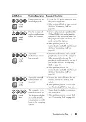
... persists, the motherboard is connected and powered on. • If the problem persists, contact Dell (see "Contacting Dell" on page 66). The diagnostic lights are not lit after the computer successfully boots to boot, contact Dell (see "Contacting Dell" on page 66). Light Pattern Steady Amber Steady Amber Steady Amber Steady Amber Steady Blue Problem Description Suggested...
... persists, the motherboard is connected and powered on. • If the problem persists, contact Dell (see "Contacting Dell" on page 66). The diagnostic lights are not lit after the computer successfully boots to boot, contact Dell (see "Contacting Dell" on page 66). Light Pattern Steady Amber Steady Amber Steady Amber Steady Amber Steady Blue Problem Description Suggested...
Setup and Quick Reference Guide
Page 47
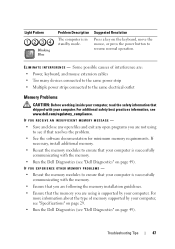
...memory. • Ensure that you are following the memory installation guidelines. • Ensure that shipped with the memory. • Run the Dell Diagnostics (see "Dell Diagnostics" on page 49). Some possible causes of memory supported by your computer, read the safety information that the memory you are using to ... • Multiple power strips connected to ensure that resolves the problem. • See the software documentation for minimum memory requirements. Light Pattern Blinking Blue Problem Description The computer is successfully communicating with your computer.
...memory. • Ensure that you are following the memory installation guidelines. • Ensure that shipped with the memory. • Run the Dell Diagnostics (see "Dell Diagnostics" on page 49). Some possible causes of memory supported by your computer, read the safety information that the memory you are using to ... • Multiple power strips connected to ensure that resolves the problem. • See the software documentation for minimum memory requirements. Light Pattern Blinking Blue Problem Description The computer is successfully communicating with your computer.

Setup and Quick Reference Guide
Page 69
..., 17 software problems, 48 reinstalling, 51 troubleshooting, 48-49 updates, 49 specifications all, 29 audio, 30 connectors, 33 controls and lights, 34 drives, 32 environmental, 37 expansion bus, 30 memory, 29 physical, 36 power, 35 processor, 29 system information, 29 video, ...Conditions, 58 transferring information to a new computer, 25 troubleshooting, 39, 58 blue screen, 48 computer not responding, 48 Dell Diagnostics, 49 memory, 47 power, 39 power light conditions, 39 program crashes, 48 programs and Windows compatibility, 48 restore to previous state, 53-54 software, 48-49 tips...
..., 17 software problems, 48 reinstalling, 51 troubleshooting, 48-49 updates, 49 specifications all, 29 audio, 30 connectors, 33 controls and lights, 34 drives, 32 environmental, 37 expansion bus, 30 memory, 29 physical, 36 power, 35 processor, 29 system information, 29 video, ...Conditions, 58 transferring information to a new computer, 25 troubleshooting, 39, 58 blue screen, 48 computer not responding, 48 Dell Diagnostics, 49 memory, 47 power, 39 power light conditions, 39 program crashes, 48 programs and Windows compatibility, 48 restore to previous state, 53-54 software, 48-49 tips...

Setup and Features Information Tech Sheet
Page 1
About Warnings WARNING: A WARNING indicates potential damage to hardware or loss of data if instructions are not followed. Front and Back View 1 234 5 6 13 14 15 16 7 17 8 9 10 12 18 11 1 hard drive activity light 3 WiFi (optional) light September 2009 19 2 network link integrity light 4 diagnostic lights Models: DCSM, DCNE, DCCY, DCSM1F, DCNE1F, and DCCY1F series. Dell™ OptiPlex™ 960 Setup and Features Information Mini Tower -
About Warnings WARNING: A WARNING indicates potential damage to hardware or loss of data if instructions are not followed. Front and Back View 1 234 5 6 13 14 15 16 7 17 8 9 10 12 18 11 1 hard drive activity light 3 WiFi (optional) light September 2009 19 2 network link integrity light 4 diagnostic lights Models: DCSM, DCNE, DCCY, DCSM1F, DCNE1F, and DCCY1F series. Dell™ OptiPlex™ 960 Setup and Features Information Mini Tower -

Setup and Features Information Tech Sheet
Page 3
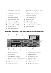
Front and Back View 1 2 3 4 12 11 10 9 13 8 76 5 14 15 16 19 18 17 5 USB 2.0 connectors (2) 7 headphone connector 9 hard drive activity light 11 WiFi (optional) light 13 expansion card slots (4) 15 power supply check light 17 security cable slot 19 back panel connectors 6 microphone connector 8 flex bay (for optional floppy drive, memory card reader, or second 3.5-inch hard disk drive) 10 link integrity light 12 diagnostic lights 14 power supply check button 16 cover release latch and padlock ring 18 power connector Small Form Factor-
Front and Back View 1 2 3 4 12 11 10 9 13 8 76 5 14 15 16 19 18 17 5 USB 2.0 connectors (2) 7 headphone connector 9 hard drive activity light 11 WiFi (optional) light 13 expansion card slots (4) 15 power supply check light 17 security cable slot 19 back panel connectors 6 microphone connector 8 flex bay (for optional floppy drive, memory card reader, or second 3.5-inch hard disk drive) 10 link integrity light 12 diagnostic lights 14 power supply check button 16 cover release latch and padlock ring 18 power connector Small Form Factor-
Setup and Features Information Tech Sheet
Page 4
... 6 headphone connector 8 USB 2.0 connectors (2) 10 link integrity light 12 diagnostic lights 14 power supply check button 16 cover release latch and padlock ring 18 power connector Back Panel Connectors - 1 power button, power light 3 CD/DVD drive (slimline) 5 Dell badge 7 microphone connector 9 hard drive activity light 11 WiFi (optional) light 13 expansion card slots (2) 15 power supply check...
... 6 headphone connector 8 USB 2.0 connectors (2) 10 link integrity light 12 diagnostic lights 14 power supply check button 16 cover release latch and padlock ring 18 power connector Back Panel Connectors - 1 power button, power light 3 CD/DVD drive (slimline) 5 Dell badge 7 microphone connector 9 hard drive activity light 11 WiFi (optional) light 13 expansion card slots (2) 15 power supply check...
Setup and Features Information Tech Sheet
Page 8
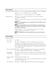
...is reading data from or writing data to the SATA hard drive or CD/DVD drive. Diagnostic lights (four) Blinking amber, solid amber, or off. Used to the network. Wi-Fi indicator Blue light - one external 5.25-inch slimline bay, one external 3.5-inch slimline bay, one external ...The blinking amber indicates a problem with two 2.5- inch HDDS or the external 3.5-inch bay as an additional internal 3.5-inch HDD bay for information about diagnostic light codes. solid blue for power-on . two 3.5-inch HDDs or two 2.5-inch HDDs Small Form Factor - two 3.5-inch hard disk drives (HDDs...
...is reading data from or writing data to the SATA hard drive or CD/DVD drive. Diagnostic lights (four) Blinking amber, solid amber, or off. Used to the network. Wi-Fi indicator Blue light - one external 5.25-inch slimline bay, one external 3.5-inch slimline bay, one external ...The blinking amber indicates a problem with two 2.5- inch HDDS or the external 3.5-inch bay as an additional internal 3.5-inch HDD bay for information about diagnostic light codes. solid blue for power-on . two 3.5-inch HDDs or two 2.5-inch HDDs Small Form Factor - two 3.5-inch hard disk drives (HDDs...

Technology Guide
Page 4
DELL™ OPTIPLEX™ 960 TECHNICAL GUIDE MINI TOWER COMPUTER (MT) VIEW FRONT VIEW 1 Hard Drive Activity Light 2 Link Integrity Light 3 Wi-FI Light (optional) 4 Diagnostic Lights 5 Power Button, Power Lights 6 Optical Drive 7 Optical Eject Button Drive 8 Optical Drive Filler Panel Flex Bay (for optional 9 floppy drive or memory card reader) 10 USB 2.0 Connectors (4) 11 Headphone ...
DELL™ OPTIPLEX™ 960 TECHNICAL GUIDE MINI TOWER COMPUTER (MT) VIEW FRONT VIEW 1 Hard Drive Activity Light 2 Link Integrity Light 3 Wi-FI Light (optional) 4 Diagnostic Lights 5 Power Button, Power Lights 6 Optical Drive 7 Optical Eject Button Drive 8 Optical Drive Filler Panel Flex Bay (for optional 9 floppy drive or memory card reader) 10 USB 2.0 Connectors (4) 11 Headphone ...

Technology Guide
Page 6
DELL™ OPTIPLEX™ 960 TECHNICAL GUIDE DESKTOP COMPUTER (DT) VIEW FRONT VIEW 1 Power Button, Power Light 2 5.25" Drive Bay 6 Bezel 7 Microphone Connector 3 Headphone Connector 8 3.5" Drive Bay 4 USB 2.0 Connectors (2) 9 Diagnostic Lights 5 Dell Badge BACK VIEW 1 Expansion card slots (4) 2 Power Supply Built in Self Test Button 3 Power Supply Status Light Cover-release Latch 4 and Padlock Ring (security screw optional) 5 Security Cable Slot 6 Power Connector 7 Back-panel Connectors 6
DELL™ OPTIPLEX™ 960 TECHNICAL GUIDE DESKTOP COMPUTER (DT) VIEW FRONT VIEW 1 Power Button, Power Light 2 5.25" Drive Bay 6 Bezel 7 Microphone Connector 3 Headphone Connector 8 3.5" Drive Bay 4 USB 2.0 Connectors (2) 9 Diagnostic Lights 5 Dell Badge BACK VIEW 1 Expansion card slots (4) 2 Power Supply Built in Self Test Button 3 Power Supply Status Light Cover-release Latch 4 and Padlock Ring (security screw optional) 5 Security Cable Slot 6 Power Connector 7 Back-panel Connectors 6
Technology Guide
Page 8
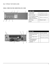
DELL™ OPTIPLEX™ 960 TECHNICAL GUIDE SMALL FORM FACTOR COMPUTER (SFF) VIEW FRONT VIEW 1 Power Button, Power Light 6 Headphone Connector 2 5.25" Drive Bay 7 Microphone Connector 3.5" Flex Bay for Floppy 3 Drive (optional) or 8 USB 2.0 Connectors (2) Media Card (optional) 4 Dell Badge 9 Diagnostic Lights 5 Bezel BACK VIEW 1 Expansion card slots (2) 5 Security Cable Slot 2 Power Supply Check Button 6 Power Cable Connector 3 Power Supply Check Light 7 Back-panel Connectors Cover-release Latch 4 and Padlock Ring (security screw optional) 8
DELL™ OPTIPLEX™ 960 TECHNICAL GUIDE SMALL FORM FACTOR COMPUTER (SFF) VIEW FRONT VIEW 1 Power Button, Power Light 6 Headphone Connector 2 5.25" Drive Bay 7 Microphone Connector 3.5" Flex Bay for Floppy 3 Drive (optional) or 8 USB 2.0 Connectors (2) Media Card (optional) 4 Dell Badge 9 Diagnostic Lights 5 Bezel BACK VIEW 1 Expansion card slots (2) 5 Security Cable Slot 2 Power Supply Check Button 6 Power Cable Connector 3 Power Supply Check Light 7 Back-panel Connectors Cover-release Latch 4 and Padlock Ring (security screw optional) 8


