Setup and Features Information Tech Sheet (Desktop, Mini-Tower, Small Form Factor)
Page 1
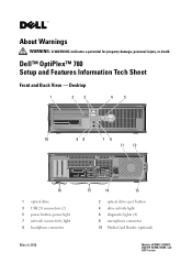
Dell™ OptiPlex™ 780 Setup and Features Information Tech Sheet Front and Back View - About Warnings WARNING: A WARNING indicates a potential for property damage, personal injury, or death. Desktop 1 2 3 4 5 10 98 76 11 12 16 1 optical drive 3 USB 2.0 connectors (2) 5 power button, power light 7 network connectivity light 9 headphone connector March 2010 15 14 13 2 optical drive eject button 4 drive activity light 6 diagnostic lights (4) 8 microphone connector 10 Media Card Reader (optional) Models: DCSM1F, DCNE1F, DCCY1F, DCSM, DCNE, and DCCY series
Dell™ OptiPlex™ 780 Setup and Features Information Tech Sheet Front and Back View - About Warnings WARNING: A WARNING indicates a potential for property damage, personal injury, or death. Desktop 1 2 3 4 5 10 98 76 11 12 16 1 optical drive 3 USB 2.0 connectors (2) 5 power button, power light 7 network connectivity light 9 headphone connector March 2010 15 14 13 2 optical drive eject button 4 drive activity light 6 diagnostic lights (4) 8 microphone connector 10 Media Card Reader (optional) Models: DCSM1F, DCNE1F, DCCY1F, DCSM, DCNE, and DCCY series

Setup and Features Information Tech Sheet (Desktop, Mini-Tower, Small Form Factor)
Page 2
... connector 16 expansion card slots (3) Front and Back View - Mini-Tower 17 1 2 16 12 11 3 15 4 10 9 5 13 8 6 7 14 1 optical drive 3 optical drive bay (optional) 5 USB 2.0 connectors (2) 7 power button, power light 9 headphone connector 11 network connectivity light 13 back panel connectors 15 cooling vents 17 cover release latch 2 optical drive eject...
... connector 16 expansion card slots (3) Front and Back View - Mini-Tower 17 1 2 16 12 11 3 15 4 10 9 5 13 8 6 7 14 1 optical drive 3 optical drive bay (optional) 5 USB 2.0 connectors (2) 7 power button, power light 9 headphone connector 11 network connectivity light 13 back panel connectors 15 cooling vents 17 cover release latch 2 optical drive eject...

Setup and Features Information Tech Sheet (Desktop, Mini-Tower, Small Form Factor)
Page 3
Small Form Factor 1 2 3 4 5 6 10 9 8 7 11 12 15 1 optical drive 3 USB 2.0 connectors (2) 5 diagnostic lights (4) 7 power button, power light 9 headphone connector 11 cover release latch 13 power connector 15 expansion card slots (2) 14 13 2 optical drive eject button 4 network connectivity light 6 drive activity light 8 microphone connector 10 Media Card Reader (optional) 12 padlock ring 14 back panel connectors Front and Back View -
Small Form Factor 1 2 3 4 5 6 10 9 8 7 11 12 15 1 optical drive 3 USB 2.0 connectors (2) 5 diagnostic lights (4) 7 power button, power light 9 headphone connector 11 cover release latch 13 power connector 15 expansion card slots (2) 14 13 2 optical drive eject button 4 network connectivity light 6 drive activity light 8 microphone connector 10 Media Card Reader (optional) 12 padlock ring 14 back panel connectors Front and Back View -
Setup and Features Information Tech Sheet (Desktop, Mini-Tower, Small Form Factor)
Page 4
... not be included if you begin any of the procedures in /microphone connector 9 VGA connector 11 DisplayPort connector 2 serial connector 4 network connector 6 line-out connector 8 USB 2.0 connectors (6) 10 eSata connector Quick Setup WARNING: Before you did not order them. For additional best practices information, see www...
... not be included if you begin any of the procedures in /microphone connector 9 VGA connector 11 DisplayPort connector 2 serial connector 4 network connector 6 line-out connector 8 USB 2.0 connectors (6) 10 eSata connector Quick Setup WARNING: Before you did not order them. For additional best practices information, see www...

Setup and Features Information Tech Sheet (Desktop, Mini-Tower, Small Form Factor)
Page 6
2 Connect the USB keyboard or mouse (optional). 3 Connect the network cable (optional). 4 Connect the modem (optional). 5 Connect the power cable(s). 6 Press the power buttons on the monitor and the computer.
2 Connect the USB keyboard or mouse (optional). 3 Connect the network cable (optional). 4 Connect the modem (optional). 5 Connect the power cable(s). 6 Press the power buttons on the monitor and the computer.

Setup and Features Information Tech Sheet (Ultra Small Form Factor)
Page 1
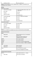
Dell™ OptiPlex™ 780 Ultra Small Form Factor Setup and Features Information Tech Sheet Front View 1 2 3 4 5 6 1 CD/DVD drive 3 drive activity light 5 network activity light 7 headphone connector 9 USB connectors (2) 9 8 7 2 power button 4 diagnostic lights (4) 6 WiFi activity light (optional) 8 microphone connector November 2009 Model: D01U Type: D01U001 About Warnings WARNING: A WARNING indicates a potential for property damage, personal injury, or death.
Dell™ OptiPlex™ 780 Ultra Small Form Factor Setup and Features Information Tech Sheet Front View 1 2 3 4 5 6 1 CD/DVD drive 3 drive activity light 5 network activity light 7 headphone connector 9 USB connectors (2) 9 8 7 2 power button 4 diagnostic lights (4) 6 WiFi activity light (optional) 8 microphone connector November 2009 Model: D01U Type: D01U001 About Warnings WARNING: A WARNING indicates a potential for property damage, personal injury, or death.

Setup and Features Information Tech Sheet (Ultra Small Form Factor)
Page 2
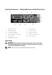
Back View 1 2 3 4 5 15 14 13 12 11 10 9 87 6 1 network activity light 3 padlock ring 5 power connector 7 line-in/microphone connector 9 DisplayPort connector 11 serial connector 13 network connector 15 WiFi antenna (optional) 2 captive thumbscrew 4 security cable slot 6 line-out connector 8 eSATA connector 10 VGA connector 12 USB connectors (5) 14 link integrity light
Back View 1 2 3 4 5 15 14 13 12 11 10 9 87 6 1 network activity light 3 padlock ring 5 power connector 7 line-in/microphone connector 9 DisplayPort connector 11 serial connector 13 network connector 15 WiFi antenna (optional) 2 captive thumbscrew 4 security cable slot 6 line-out connector 8 eSATA connector 10 VGA connector 12 USB connectors (5) 14 link integrity light

Setup and Features Information Tech Sheet (Ultra Small Form Factor)
Page 3
c The VGA cable to a DisplayPort adapter. 2 Connect the USB keyboard or mouse (optional). 3 Connect the network cable (optional). For additional best practices information, see www.dell.com/regulatory_compliance. b The DisplayPort cable. NOTE: Some devices may not be included if you begin any of the following cables: a The blue VGA cable. Quick Setup WARNING: Before you did not order them. 1 Connect the monitor using only one of the procedures in this section, read the safety information that shipped with your computer.
c The VGA cable to a DisplayPort adapter. 2 Connect the USB keyboard or mouse (optional). 3 Connect the network cable (optional). For additional best practices information, see www.dell.com/regulatory_compliance. b The DisplayPort cable. NOTE: Some devices may not be included if you begin any of the following cables: a The blue VGA cable. Quick Setup WARNING: Before you did not order them. 1 Connect the monitor using only one of the procedures in this section, read the safety information that shipped with your computer.

Service Manual
Page 7
... card capable of 10/100/1000 Mb/s communication Intel® Q45 Express chipset w/ICH10DO eight 24 64 Mb PCI 2.3 PCI Express 2.0 SATA 1.0A and 2.0 eSATA USB 2.0 PCI: 133 MB/s PCI Express: x1-slot bidirectional speed - 250 MB/s x16-slot bidirectional speed - 8 GB/s SATA: 1.5 Gbps and 3.0 Gbps eSATA: 3.0 Gbps...
... card capable of 10/100/1000 Mb/s communication Intel® Q45 Express chipset w/ICH10DO eight 24 64 Mb PCI 2.3 PCI Express 2.0 SATA 1.0A and 2.0 eSATA USB 2.0 PCI: 133 MB/s PCI Express: x1-slot bidirectional speed - 250 MB/s x16-slot bidirectional speed - 8 GB/s SATA: 1.5 Gbps and 3.0 Gbps eSATA: 3.0 Gbps...
Service Manual
Page 8
... Board Connectors PCI 2.3 Mini-tower data width (maximum) - 32 bits two 120-pin connectors External Connectors Audio Back panel Front panel eSATA Network Parallel Serial USB Front panel Back panel Video two connectors for line-in -1 Media Card Readers one bay one bay one slimline bay for headphones and microphone one...
... Board Connectors PCI 2.3 Mini-tower data width (maximum) - 32 bits two 120-pin connectors External Connectors Audio Back panel Front panel eSATA Network Parallel Serial USB Front panel Back panel Video two connectors for line-in -1 Media Card Readers one bay one bay one slimline bay for headphones and microphone one...
Service Manual
Page 9
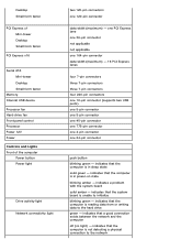
...) - 16 PCI Express lanes four 7-pin connectors three 7-pin connectors three 7-pin connectors four 240-pin connectors one 10-pin connector (supports two USB ports) one 5-pin connector one 5-pin connector one 40-pin connector one 775-pin connector one 4-pin connector one 120-pin connector data width (maximum...form factor PCI Express x1 Mini-tower Desktop Small form factor PCI Express x16 Serial ATA Mini-tower Desktop Small form factor Memory Internal USB device Processor fan Hard-drive fan Front panel control Processor Power 12V Power Controls and Lights Front of the computer Power button Power ...
...) - 16 PCI Express lanes four 7-pin connectors three 7-pin connectors three 7-pin connectors four 240-pin connectors one 10-pin connector (supports two USB ports) one 5-pin connector one 5-pin connector one 40-pin connector one 775-pin connector one 4-pin connector one 120-pin connector data width (maximum...form factor PCI Express x1 Mini-tower Desktop Small form factor PCI Express x16 Serial ATA Mini-tower Desktop Small form factor Memory Internal USB device Processor fan Hard-drive fan Front panel control Processor Power 12V Power Controls and Lights Front of the computer Power button Power ...
Service Manual
Page 12
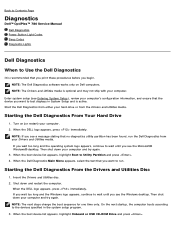
... appears, press immediately. When the boot device list appears, highlight Onboard or USB CD-ROM Drive and press . Back to Contents Page Diagnostics Dell™ OptiPlex™ 780 Service Manual Dell Diagnostics Power Button Light Codes Beep Codes Diagnostic Lights Dell Diagnostics When to wait until you see the Microsoft® Windows® desktop. Shut down...
... appears, press immediately. When the boot device list appears, highlight Onboard or USB CD-ROM Drive and press . Back to Contents Page Diagnostics Dell™ OptiPlex™ 780 Service Manual Dell Diagnostics Power Button Light Codes Beep Codes Diagnostic Lights Dell Diagnostics When to wait until you see the Microsoft® Windows® desktop. Shut down...
Service Manual
Page 15
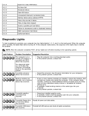
...a normal off . A possible graphics card failure has occurred. Reseat any installed graphics cards. If the problem persists, contact Dell . A possible processor failure has occurred. A possible floppy drive or hard drive failure has occurred. Memory modules are installed,...condition or a possible pre-BIOS failure has occurred. If two or more memory modules are detected, but a memory failure has occurred. Reinstall all USB devices and check all power and data cables. 3-4-3 4-2-1 4-2-2 4-2-3 4-2-4 4-3-1 4-3-3 4-3-4 4-4-1 4-4-2 4-4-3 4-4-4 Search for your computer. When...
...a normal off . A possible graphics card failure has occurred. Reseat any installed graphics cards. If the problem persists, contact Dell . A possible processor failure has occurred. A possible floppy drive or hard drive failure has occurred. Memory modules are installed,...condition or a possible pre-BIOS failure has occurred. If two or more memory modules are detected, but a memory failure has occurred. Reinstall all USB devices and check all power and data cables. 3-4-3 4-2-1 4-2-2 4-2-3 4-2-4 4-3-1 4-3-3 4-3-4 4-4-1 4-4-2 4-4-3 4-4-4 Search for your computer. When...
Service Manual
Page 18
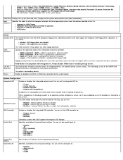
...Size, and DIMM_4 Size. . System Configuration Integrated NIC Enables or disables the integrated network card. Internal USB for Flex Bay is incompatible with USB support will recognize USB Storage Identifies and defines the parallel port settings. Processor information: Displays the Processor Type, Processor Speed, ...native resources assigned to : Disable Enable (default) Enable with PXE Enable with ImageSever ImageServe is enable No Boot - You can set the USB controller to : Disable AT PS/2 (default) EPP ECP No DMA ECP DMA 1 ECP DMA 3 Parallel Port Address Serial Port #1...
...Size, and DIMM_4 Size. . System Configuration Integrated NIC Enables or disables the integrated network card. Internal USB for Flex Bay is incompatible with USB support will recognize USB Storage Identifies and defines the parallel port settings. Processor information: Displays the Processor Type, Processor Speed, ...native resources assigned to : Disable Enable (default) Enable with PXE Enable with ImageSever ImageServe is enable No Boot - You can set the USB controller to : Disable AT PS/2 (default) EPP ECP No DMA ECP DMA 1 ECP DMA 3 Parallel Port Address Serial Port #1...

Service Manual
Page 19
Enables or disables the following onboard devices: Front USB Rear Dual USB Rear Quad USB PCI slots Audio Video Primary Video This field determines which video controller will not complete installation when Value the maximum CPUID Function supported is installed. ...
Enables or disables the following onboard devices: Front USB Rear Dual USB Rear Quad USB PCI slots Audio Video Primary Video This field determines which video controller will not complete installation when Value the maximum CPUID Function supported is installed. ...

Technical Guide
Page 3
DELL™ OPTIPLEX™ 780 TECHNICAL GUIDEBOOK V2.0 MINI TOWER COMPUTER (MT) VIEW FRONT VIEW 1 Optical Drive (optional) 2 Optical Drive Eject Button 3 Optical Drive Bay 7 Power Button, Power Light 8 Diagnostic... 1 Power Connector 2 Back-Panel Connectors 3 Expansion Card Slots (4) 4 Power-Supply Vent 5 Chassis Lock Loop 6 Cover Release Latch 4 Media Card Reader (optional) 10 Microphone Connector 5 USB 2.0 Connectors (2) 11 Network Connectivity Light 6 Hard Drive Activity Light BACK PANEL CONNECTORS 1 Parallel Connector 7 Line-in Connector 2 Serial Connector 3 Link Integrity Light...
DELL™ OPTIPLEX™ 780 TECHNICAL GUIDEBOOK V2.0 MINI TOWER COMPUTER (MT) VIEW FRONT VIEW 1 Optical Drive (optional) 2 Optical Drive Eject Button 3 Optical Drive Bay 7 Power Button, Power Light 8 Diagnostic... 1 Power Connector 2 Back-Panel Connectors 3 Expansion Card Slots (4) 4 Power-Supply Vent 5 Chassis Lock Loop 6 Cover Release Latch 4 Media Card Reader (optional) 10 Microphone Connector 5 USB 2.0 Connectors (2) 11 Network Connectivity Light 6 Hard Drive Activity Light BACK PANEL CONNECTORS 1 Parallel Connector 7 Line-in Connector 2 Serial Connector 3 Link Integrity Light...
Technical Guide
Page 4
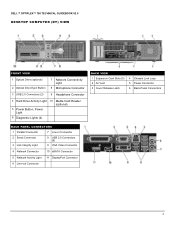
DELL™ OPTIPLEX™ 780 TECHNICAL GUIDEBOOK V2.0 DESKTOP COMPUTER (DT) VIEW FRONT VIEW 1 Optical Drive (optional) 2 Optical Drive Eject Button 7 Network Connectivity Light 8 Microphone Connector 3 USB 2.0 Connectors (2) 9 Headphone Connector 4 Hard Drive Activity Light 10 Media Card Reader (optional) 5 Power Button, ... PANEL CONNECTORS 1 Parallel Connector 7 Line-in Connector 2 Serial Connector 3 Link Integrity Light 8 USB 2.0 Connectors (6) 9 VGA Video Connector 4 Network Connector 10 eSATA Connector 5 Network Activity Light 11 DisplayPort Connector 6 Line-out Connector 4
DELL™ OPTIPLEX™ 780 TECHNICAL GUIDEBOOK V2.0 DESKTOP COMPUTER (DT) VIEW FRONT VIEW 1 Optical Drive (optional) 2 Optical Drive Eject Button 7 Network Connectivity Light 8 Microphone Connector 3 USB 2.0 Connectors (2) 9 Headphone Connector 4 Hard Drive Activity Light 10 Media Card Reader (optional) 5 Power Button, ... PANEL CONNECTORS 1 Parallel Connector 7 Line-in Connector 2 Serial Connector 3 Link Integrity Light 8 USB 2.0 Connectors (6) 9 VGA Video Connector 4 Network Connector 10 eSATA Connector 5 Network Activity Light 11 DisplayPort Connector 6 Line-out Connector 4
Technical Guide
Page 5
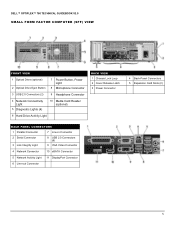
DELL™ OPTIPLEX™ 780 TECHNICAL GUIDEBOOK V2.0 SMALL FORM FACTOR COMPUTER (SFF) VIEW FRONT VIEW 1 Optical Drive (optional) 2 Optical Drive Eject Button 7 Power Button, Power Light 8 Microphone Connector 3 USB 2.0 Connectors (2) 9 Headphone Connector 4 Network Connectivity Light 5 Diagnostic Lights (4) 10 Media Card...PANEL CONNECTORS 1 Parallel Connector 7 Line-in Connector 2 Serial Connector 3 Link Integrity Light 8 USB 2.0 Connectors (6) 9 VGA Video Connector 4 Network Connector 10 eSATA Connector 5 Network Activity Light 11 DisplayPort Connector 6 Line-out Connector 5
DELL™ OPTIPLEX™ 780 TECHNICAL GUIDEBOOK V2.0 SMALL FORM FACTOR COMPUTER (SFF) VIEW FRONT VIEW 1 Optical Drive (optional) 2 Optical Drive Eject Button 7 Power Button, Power Light 8 Microphone Connector 3 USB 2.0 Connectors (2) 9 Headphone Connector 4 Network Connectivity Light 5 Diagnostic Lights (4) 10 Media Card...PANEL CONNECTORS 1 Parallel Connector 7 Line-in Connector 2 Serial Connector 3 Link Integrity Light 8 USB 2.0 Connectors (6) 9 VGA Video Connector 4 Network Connector 10 eSATA Connector 5 Network Activity Light 11 DisplayPort Connector 6 Line-out Connector 5
Technical Guide
Page 6
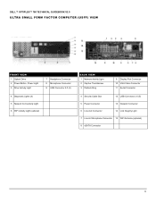
DELL™ OPTIPLEX™ 780 TECHNICAL GUIDEBOOK V2.0 ULTRA SMALL FORM FACTOR COMPUTER (USFF) VIEW FRONT VIEW 1 Optical Drive 2 Power Button, Power Light 3 Drive Activity Light 7 Headphone Connector 8 Microphone Connector 9 USB Connector 2.0 (2) 4 Diagnostic Lights (4) 5 Network Connectivity Light 6 WiFi Activity Light (optional... Thumbscrew 3 Padlock Ring 9 Display Port Connector 10 VGA Video Connector 11 Serial Connector 4 Security Cable Slot 12 USB Connector 2.0 (5) 5 Power Connector 13 Network Connector 6 Line-Out Connector 14 Link Integrity Light 7 Line-in/ Microphone Connector 15...
DELL™ OPTIPLEX™ 780 TECHNICAL GUIDEBOOK V2.0 ULTRA SMALL FORM FACTOR COMPUTER (USFF) VIEW FRONT VIEW 1 Optical Drive 2 Power Button, Power Light 3 Drive Activity Light 7 Headphone Connector 8 Microphone Connector 9 USB Connector 2.0 (2) 4 Diagnostic Lights (4) 5 Network Connectivity Light 6 WiFi Activity Light (optional... Thumbscrew 3 Padlock Ring 9 Display Port Connector 10 VGA Video Connector 11 Serial Connector 4 Security Cable Slot 12 USB Connector 2.0 (5) 5 Power Connector 13 Network Connector 6 Line-Out Connector 14 Link Integrity Light 7 Line-in/ Microphone Connector 15...

Technical Guide
Page 12
...: MT supports full height card, DT supports low profile card or full height card with optional riser. See chassis diagrams section for port/connector locations USB 2.0 Serial eSATA Parallel Network Connector (RJ-45) PS/2 1394 Controller Video: MT DT SFF 2 Front, 6 Rear, 1 Internal 1 rear, ... for microphone or stereo Line out for microphone Line in card 1 Rear 1 Front 1 Rear 1 Front, 1 Rear X X 12 DELL™ OPTIPLEX™ 780 TECHNICAL GUIDEBOOK V2.0 GRAPHICS/VIDEO CONTROLLER NOTE: MT supports full height card, DT supports low profile card or full height card with optional...
...: MT supports full height card, DT supports low profile card or full height card with optional riser. See chassis diagrams section for port/connector locations USB 2.0 Serial eSATA Parallel Network Connector (RJ-45) PS/2 1394 Controller Video: MT DT SFF 2 Front, 6 Rear, 1 Internal 1 rear, ... for microphone or stereo Line out for microphone Line in card 1 Rear 1 Front 1 Rear 1 Front, 1 Rear X X 12 DELL™ OPTIPLEX™ 780 TECHNICAL GUIDEBOOK V2.0 GRAPHICS/VIDEO CONTROLLER NOTE: MT supports full height card, DT supports low profile card or full height card with optional...

