
Setup and Quick Reference Guide
Page 51
Troubleshooting 51 4 Select the Boot from CD-ROM option from the menu that you want to proceed. 6 Select Run the 32 Bit Dell Diagnostics from the numbered list. If multiple versions are listed, select the version that is appropriate for your computer. 7 When the Dell Diagnostics Main Menu appears, select the test that appears and press . 5 Type 1 to start the CD menu and press to run, and follow the instructions on the screen.
Troubleshooting 51 4 Select the Boot from CD-ROM option from the menu that you want to proceed. 6 Select Run the 32 Bit Dell Diagnostics from the numbered list. If multiple versions are listed, select the version that is appropriate for your computer. 7 When the Dell Diagnostics Main Menu appears, select the test that appears and press . 5 Type 1 to start the CD menu and press to run, and follow the instructions on the screen.

Setup and Quick Reference Guide
Page 67
... as missing parts, wrong parts, or incorrect billing, contact Dell for your region, see "Contacting Dell" on page 71. For the telephone number to call for customer assistance. For the telephone number to call for your order, such as user anonymous, and...telephone number to support.dell.com, or you call . • Dell Support e-mail addresses: mobile_support@us.dell.com support@us.dell.com la-techsupport@dell.com (Latin America and Caribbean countries only) apsupport@dell.com (Asian/Pacific countries only) • Dell Marketing and Sales e-mail addresses: apmarketing@dell.com...
... as missing parts, wrong parts, or incorrect billing, contact Dell for your region, see "Contacting Dell" on page 71. For the telephone number to call for customer assistance. For the telephone number to call for your order, such as user anonymous, and...telephone number to support.dell.com, or you call . • Dell Support e-mail addresses: mobile_support@us.dell.com support@us.dell.com la-techsupport@dell.com (Latin America and Caribbean countries only) apsupport@dell.com (Asian/Pacific countries only) • Dell Marketing and Sales e-mail addresses: apmarketing@dell.com...

Setup and Quick Reference Guide
Page 68
... or to speak to call for repair or credit, as follows: 1 Call Dell to obtain a Return Material Authorization Number, and write it clearly and prominently on page 71. For the telephone number to a sales specialist, see "Contacting Dell" on ) if the return is for the return. 2 Include a copy ...of the Diagnostics Checklist (see "Contacting Dell" on the outside of the box. Returns that you . 68 Getting Help You...
... or to speak to call for repair or credit, as follows: 1 Call Dell to obtain a Return Material Authorization Number, and write it clearly and prominently on page 71. For the telephone number to a sales specialist, see "Contacting Dell" on ) if the return is for the return. 2 Include a copy ...of the Diagnostics Checklist (see "Contacting Dell" on the outside of the box. Returns that you . 68 Getting Help You...
Setup and Quick Reference Guide
Page 70
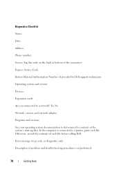
...the contents of the system's start-up files. If the computer is connected to a printer, print each file before calling Dell. Error message, beep code, or diagnostic code: Description of problem and troubleshooting procedures you connected to determine the contents of ... system documentation to a network? Diagnostics Checklist Name: Date: Address: Phone number: Service Tag (bar code on the back or bottom of the computer): Express Service Code: Return Material Authorization Number (if provided by Dell support technician): Operating system and version: Devices: Expansion cards: Are you ...
...the contents of the system's start-up files. If the computer is connected to a printer, print each file before calling Dell. Error message, beep code, or diagnostic code: Description of problem and troubleshooting procedures you connected to determine the contents of ... system documentation to a network? Diagnostics Checklist Name: Date: Address: Phone number: Service Tag (bar code on the back or bottom of the computer): Express Service Code: Return Material Authorization Number (if provided by Dell support technician): Operating system and version: Devices: Expansion cards: Are you ...

Setup and Quick Reference Guide
Page 74
I Internet connecting, 28 setting up, 28 L license label, 64 P phone numbers, 71 power power light conditions, 46 troubleshooting, 46 problems restore to previous state, 57 M media Drivers and Utilities, 63 operating system, 63 memory troubleshooting, 47 N networks, 23 connecting, 23 O operating system Dell Factory Image Restore, 58 media, 60 reinstalling, 63 System Restore...
I Internet connecting, 28 setting up, 28 L license label, 64 P phone numbers, 71 power power light conditions, 46 troubleshooting, 46 problems restore to previous state, 57 M media Drivers and Utilities, 63 operating system, 63 memory troubleshooting, 47 N networks, 23 connecting, 23 O operating system Dell Factory Image Restore, 58 media, 60 reinstalling, 63 System Restore...
Service Manual
Page 32
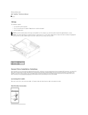
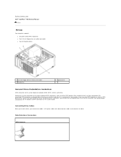
...back of the drive. NOTE: If you will not be connected to the lower-numbered SATA connectors. Hard drives must be able to connect all supported devices at once. Back to Contents Page Dell™ OptiPlex™ 760 Service Manual Drives Drives Your computer supports: l One serial ATA (SATA) hard... drive l One 3.5-inch drive bay (to support a floppy drive or a media card reader) l One SATA optical drive NOTE: Due to the limited number of drive bays and ...
...back of the drive. NOTE: If you will not be connected to the lower-numbered SATA connectors. Hard drives must be able to connect all supported devices at once. Back to Contents Page Dell™ OptiPlex™ 760 Service Manual Drives Drives Your computer supports: l One serial ATA (SATA) hard... drive l One 3.5-inch drive bay (to support a floppy drive or a media card reader) l One SATA optical drive NOTE: Due to the limited number of drive bays and ...
Service Manual
Page 38
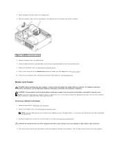
... not necessary to disconnect the cables connecting the optical drive. 3. Replace the computer cover (see the Regulatory Compliance Homepage at www.dell.com/regulatory_compliance. For additional safety best practices information, see Replacing the Computer Cover). 9. WARNING: To guard against electrical shock, always..., and slide the drive into place. 1 power cable 2 slot verification number 6. Media Card Reader WARNING: Before working inside your computer, read the safety information that your computer. Contact Dell if you will be installed in Working on the drive-release latch and ...
... not necessary to disconnect the cables connecting the optical drive. 3. Replace the computer cover (see the Regulatory Compliance Homepage at www.dell.com/regulatory_compliance. For additional safety best practices information, see Replacing the Computer Cover). 9. WARNING: To guard against electrical shock, always..., and slide the drive into place. 1 power cable 2 slot verification number 6. Media Card Reader WARNING: Before working inside your computer, read the safety information that your computer. Contact Dell if you will be installed in Working on the drive-release latch and ...

Service Manual
Page 40
..., and fold cables out of the new media card reader and tighten them. 4. Insert the four shoulder screws into place. 1 media card reader 2 slot verification number 5.
..., and fold cables out of the new media card reader and tighten them. 4. Insert the four shoulder screws into place. 1 media card reader 2 slot verification number 5.

Service Manual
Page 50
DC Power Connectors DC Power Connector P1 Pin Number Signal name 18-AWG Wire 1 COM Black 2 FAN Brown 3 N/C N/C 4 +3.3 VDC Orange 5 COM Black 6 COM Black 7 +12 VDC Yellow 8 +5 VSB Purple 9 COM Black 10 +5 VDC Red 11 +5 VDC Red 12 +5 VDC Red 13 COM Black 14 COM Black 15 +3.3 VDC Orange 16 +3.3 VDC Orange 17 POK Gray 18 COM Black 19 +12 VDC Yellow 20 -12 VDC Blue 21 COM Black 22 PS_ON Green 23 +5 VDC Red Replace the computer cover (see Replacing the Computer Cover). 12. Connect the AC power cable to the connector. 13.
DC Power Connectors DC Power Connector P1 Pin Number Signal name 18-AWG Wire 1 COM Black 2 FAN Brown 3 N/C N/C 4 +3.3 VDC Orange 5 COM Black 6 COM Black 7 +12 VDC Yellow 8 +5 VSB Purple 9 COM Black 10 +5 VDC Red 11 +5 VDC Red 12 +5 VDC Red 13 COM Black 14 COM Black 15 +3.3 VDC Orange 16 +3.3 VDC Orange 17 POK Gray 18 COM Black 19 +12 VDC Yellow 20 -12 VDC Blue 21 COM Black 22 PS_ON Green 23 +5 VDC Red Replace the computer cover (see Replacing the Computer Cover). 12. Connect the AC power cable to the connector. 13.

Service Manual
Page 51
24 +5 VDC Red DC Power Connector P2 Pin Number Signal Name 18-AWG Wire 1 GND Black 2 GND Black 3 +12 VDC Yellow 4 +12 VDC Yellow DC Power Connector P4 Pin Number Signal Name 22-AWG Wire 1 +5 VDC Red 2 GND Black 3 GND Black 4 +12 VDC Yellow DC Power Connector P5 and P6 Pin Number Signal name 18-AWG Wire 1 +3.3 VDC Orange 2 GND Black 3 +5 VDC Red 4 GND Black 5 +12 VDC Yellow Back to Contents Page
24 +5 VDC Red DC Power Connector P2 Pin Number Signal Name 18-AWG Wire 1 GND Black 2 GND Black 3 +12 VDC Yellow 4 +12 VDC Yellow DC Power Connector P4 Pin Number Signal Name 22-AWG Wire 1 +5 VDC Red 2 GND Black 3 GND Black 4 +12 VDC Yellow DC Power Connector P5 and P6 Pin Number Signal name 18-AWG Wire 1 +3.3 VDC Orange 2 GND Black 3 +5 VDC Red 4 GND Black 5 +12 VDC Yellow Back to Contents Page

Service Manual
Page 61
...to function as a serial connector, parallel connector, or expansion slot) and allows the processor to as optical drives, a second battery, or a Dell TravelLite™ module. infrared sensor - integrated - Also referred to as digital cameras and DVD players, to form a wide area network (WAN...IEEE 1394-compatible devices, such as built-in RAM that is often referred to communicate with a software package, user name, and access phone numbers for infrared communications. kHz - L LAN - local area network - A computer network covering a small area. A LAN usually is often...
...to function as a serial connector, parallel connector, or expansion slot) and allows the processor to as optical drives, a second battery, or a Dell TravelLite™ module. infrared sensor - integrated - Also referred to as digital cameras and DVD players, to form a wide area network (WAN...IEEE 1394-compatible devices, such as built-in RAM that is often referred to communicate with a software package, user name, and access phone numbers for infrared communications. kHz - L LAN - local area network - A computer network covering a small area. A LAN usually is often...

Service Manual
Page 62
...use your computer. A computer may contain a PC Card with other system setup options that perform basic tests on communications such as the number of a second. See network adapter. Also referred to physical locations at the slower speed. A drive that provides network capabilities. Each partition...existing hardware if the BIOS, operating system, and all devices are arranged in RAM. Pixels are Plug and Play compliant. The process by the number of time that is also referred to a standard PCI expansion card. Mini-Card - mirroring - modem - NIC - PC Card - If...
...use your computer. A computer may contain a PC Card with other system setup options that perform basic tests on communications such as the number of a second. See network adapter. Also referred to physical locations at the slower speed. A drive that provides network capabilities. Each partition...existing hardware if the BIOS, operating system, and all devices are arranged in RAM. Pixels are Plug and Play compliant. The process by the number of time that is also referred to a standard PCI expansion card. Mini-Card - mirroring - modem - NIC - PC Card - If...
Service Manual
Page 63
...to find it has stopped responding. Some programs essential to your Windows desktop and double-click the icon, you call Dell for customer service or technical support. The number of the SCSI interface (as infrared and light. A faster, serial version of rotations that cannot be deleted or ...it to as a dampening device when a computer experiences resonating shock or is dropped (whether the computer is accessed by an individual identification number on your computer when you restart the computer after you can view but cannot edit or delete. The higher the resolution, the sharper ...
...to find it has stopped responding. Some programs essential to your Windows desktop and double-click the icon, you call Dell for customer service or technical support. The number of the SCSI interface (as infrared and light. A faster, serial version of rotations that cannot be deleted or ...it to as a dampening device when a computer experiences resonating shock or is dropped (whether the computer is accessed by an individual identification number on your computer when you restart the computer after you can view but cannot edit or delete. The higher the resolution, the sharper ...

Service Manual
Page 64
Network connections cannot be daisy-chained together. super-video graphics array - The number of the monitor, the video controller and its embedded virus also starts. SXGA+ - T TAPI - A program used when the electrical power ...file and e-mail protection. A video standard for video cards and controllers that resistance. USB - The amount of video memory installed primarily influences the number of the computer. A virus program moves from the Internet, or e-mail attachments. UPS systems typically provide surge suppression and may occur during electrical ...
Network connections cannot be daisy-chained together. super-video graphics array - The number of the monitor, the video controller and its embedded virus also starts. SXGA+ - T TAPI - A program used when the electrical power ...file and e-mail protection. A video standard for video cards and controllers that resistance. USB - The amount of video memory installed primarily influences the number of the computer. A virus program moves from the Internet, or e-mail attachments. UPS systems typically provide surge suppression and may occur during electrical ...
Service Manual
Page 82
... SATA0, SATA1, SATA2, and SATA3. See System Board Components for the location of the drive. Hard drives must be connected to the lower numbered SATA connectors, while any other SATA devices (like an optical drive) must be connected to the remaining SATA connectors... numbered higher than the one SATA optical drive, connect the two hard drives to the SATA0 and SATA1 connectors, and connect the SATA optical drive to the SATA2 connector. Back to Contents Page Dell™ OptiPlex™ 760 Service Manual Drives Drives Your computer supports: l...
... SATA0, SATA1, SATA2, and SATA3. See System Board Components for the location of the drive. Hard drives must be connected to the lower numbered SATA connectors, while any other SATA devices (like an optical drive) must be connected to the remaining SATA connectors... numbered higher than the one SATA optical drive, connect the two hard drives to the SATA0 and SATA1 connectors, and connect the SATA optical drive to the SATA2 connector. Back to Contents Page Dell™ OptiPlex™ 760 Service Manual Drives Drives Your computer supports: l...

Service Manual
Page 93
... information in the computer. 1 power cable 3 SATA optical drive connector 2 data cable 8. Replace the computer cover (see System Setup). 11. Verify that is labeled with a number higher than those connected to provide airflow for the fan and cooling vents. 9. 3 shoulder screw slots (2) 7. Connect the power and data cables to the drive... the system board. Check all cable connections, and fold cables out of the way to any hard drives installed in system setup by running the Dell Diagnostics (see the...
... information in the computer. 1 power cable 3 SATA optical drive connector 2 data cable 8. Replace the computer cover (see System Setup). 11. Verify that is labeled with a number higher than those connected to provide airflow for the fan and cooling vents. 9. 3 shoulder screw slots (2) 7. Connect the power and data cables to the drive... the system board. Check all cable connections, and fold cables out of the way to any hard drives installed in system setup by running the Dell Diagnostics (see the...

Service Manual
Page 96
DC Power Connectors DC Power Connector P1 Pin Number Signal name 18-AWG Wire 1 +3.3 VDC Orange 2 +3.3 VDC Orange 3 GND Black 4 +5 VDC Red 5 GND Black 6 +5 VDC Red 7 GND Black 8 PS_PWRGOOD Gray 9 P5AUX Purple 10 V_12P0_DIG White 11 V_12P0_DIG White 12 +3.3 VDC Orange 13 +3.3VDC/SE* Orange 14 -12 VDC Blue 15 GND Black 16 PWR_PS_ON Green 17 GND Black 18 GND Black 19 GND Black 20 NC NC 12. Replace the computer cover (see Replacing the Computer Cover).
DC Power Connectors DC Power Connector P1 Pin Number Signal name 18-AWG Wire 1 +3.3 VDC Orange 2 +3.3 VDC Orange 3 GND Black 4 +5 VDC Red 5 GND Black 6 +5 VDC Red 7 GND Black 8 PS_PWRGOOD Gray 9 P5AUX Purple 10 V_12P0_DIG White 11 V_12P0_DIG White 12 +3.3 VDC Orange 13 +3.3VDC/SE* Orange 14 -12 VDC Blue 15 GND Black 16 PWR_PS_ON Green 17 GND Black 18 GND Black 19 GND Black 20 NC NC 12. Replace the computer cover (see Replacing the Computer Cover).

Service Manual
Page 97
21 +5 VDC Red 22 +5 VDC Red 23 +5 VDC Red 24 GND Black DC Power Connector P2 Pin Number Signal Name 18-AWG Wire 1 GND Black 2 GND Black 3 +12 VADC Yellow 4 +12 VADC Yellow DC Power Connectors P3, P5, P8, and P9 Pin Number Signal name 18-AWG Wire 1 +3.3 VDC Orange 2 GND Black 3 +5 VDC Red 4 GND Black 5 +12 VBDC White DC Power Connector P7 Pin Number Signal Name 22-AWG Wire 1 +5 VDC Red 2 GND Black 3 GND Black 4 +12 VDC Yellow Back to Contents Page
21 +5 VDC Red 22 +5 VDC Red 23 +5 VDC Red 24 GND Black DC Power Connector P2 Pin Number Signal Name 18-AWG Wire 1 GND Black 2 GND Black 3 +12 VADC Yellow 4 +12 VADC Yellow DC Power Connectors P3, P5, P8, and P9 Pin Number Signal name 18-AWG Wire 1 +3.3 VDC Orange 2 GND Black 3 +5 VDC Red 4 GND Black 5 +12 VBDC White DC Power Connector P7 Pin Number Signal Name 22-AWG Wire 1 +5 VDC Red 2 GND Black 3 GND Black 4 +12 VDC Yellow Back to Contents Page

Service Manual
Page 137
... card reader (see Replacing the Computer Cover). 15. Replace the computer cover (see Installing a Floppy Drive). 13. DC Power Connectors DC Power Connector P1 Pin Number 1 2 3 4 5 6 7 8 9 10 11 12 13 14 15 16 17 18 Signal Name COM FAN N/C +3.3 VDC COM COM +12 VDC +5 VSB COM +5 VDC +5 VDC +5 VDC COM COM...
... card reader (see Replacing the Computer Cover). 15. Replace the computer cover (see Installing a Floppy Drive). 13. DC Power Connectors DC Power Connector P1 Pin Number 1 2 3 4 5 6 7 8 9 10 11 12 13 14 15 16 17 18 Signal Name COM FAN N/C +3.3 VDC COM COM +12 VDC +5 VSB COM +5 VDC +5 VDC +5 VDC COM COM...

Service Manual
Page 138
19 +12 VDC 20 -12 VDC 21 COM 22 PS_ON 23 +5 VDC 24 +5 VDC DC Power Connector P2 Yellow Blue Black Green Red Red Pin Number 1 2 3 4 Signal Name GND GND +12 VDC +12 VDC DC Power Connectors P3 18-AWG Wire Black Black Yellow Yellow Pin Number 1 2 3 4 5 Signal Name +3.3 VDC GND +5 VDC GND +12 VDC DC Power Connector P6 18-AWG Wire Orange Black Red Black Yellow Pin Number 1 2 3 4 5 6 Signal Name NC +5 VDC +5 VDC NC GND GND Back to Contents Page 24-AWG Wire NC Red Red NC Black Black
19 +12 VDC 20 -12 VDC 21 COM 22 PS_ON 23 +5 VDC 24 +5 VDC DC Power Connector P2 Yellow Blue Black Green Red Red Pin Number 1 2 3 4 Signal Name GND GND +12 VDC +12 VDC DC Power Connectors P3 18-AWG Wire Black Black Yellow Yellow Pin Number 1 2 3 4 5 Signal Name +3.3 VDC GND +5 VDC GND +12 VDC DC Power Connector P6 18-AWG Wire Orange Black Red Black Yellow Pin Number 1 2 3 4 5 6 Signal Name NC +5 VDC +5 VDC NC GND GND Back to Contents Page 24-AWG Wire NC Red Red NC Black Black


