
Tower Owners Manual
Page 2
......22 Memory module...23 Removing memory module...23 Installing memory module...23 Expansion card...24 Removing PCIe expansion card...24 Installing PCIe expansion card...25 Power supply unit...26 Removing power supply unit (PSU)...26 Installing power supply unit (PSU)...27 2 Contents
......22 Memory module...23 Removing memory module...23 Installing memory module...23 Expansion card...24 Removing PCIe expansion card...24 Installing PCIe expansion card...25 Power supply unit...26 Removing power supply unit (PSU)...26 Installing power supply unit (PSU)...27 2 Contents
Tower Owners Manual
Page 4
... 7: Troubleshooting your computer 71 Diagnostic power LED codes...71 Power LED issue...72 Dell Enhanced Pre-Boot System Assessment (ePSA) diagnostic 3.0 72 Running the ePSA Diagnostics...72 Diagnostic error messages...73 System error messages...76 Power Supply Unit PSU Built-in Self Test ...Audio specifications...79 Communication specifications...80 Storage specifications...80 Ports and connectors specifications...80 Power supply specifications...81 Physical dimension specifications...81 System board layout...82 Controls and lights specifications...82 Environmental specifications...83 Chapter ...
... 7: Troubleshooting your computer 71 Diagnostic power LED codes...71 Power LED issue...72 Dell Enhanced Pre-Boot System Assessment (ePSA) diagnostic 3.0 72 Running the ePSA Diagnostics...72 Diagnostic error messages...73 System error messages...76 Power Supply Unit PSU Built-in Self Test ...Audio specifications...79 Communication specifications...80 Storage specifications...80 Ports and connectors specifications...80 Power supply specifications...81 Physical dimension specifications...81 System board layout...82 Controls and lights specifications...82 Environmental specifications...83 Chapter ...
Tower Owners Manual
Page 9
... door • Storage • Optical drive • M.2 PCIe SSD • SD card reader • Memory module • Expansion card • Power supply unit • VGA daughter board • Intrusion switch • Power switch • Speaker • Coin cell battery • Heat sink assembly • Processor • System fan • System board Recommended tools...
... door • Storage • Optical drive • M.2 PCIe SSD • SD card reader • Memory module • Expansion card • Power supply unit • VGA daughter board • Intrusion switch • Power switch • Speaker • Coin cell battery • Heat sink assembly • Processor • System fan • System board Recommended tools...

Tower Owners Manual
Page 26
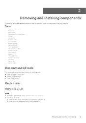
... front panel door. 4. c. Press the release tab [1]. b. Remove the: a. To remove the PSU: a. bezel 3. Slide and lift the PSU away from the retention clip [4]. Power supply unit Removing power supply unit (PSU) Steps 1. Follow the procedure in Before working inside your computer. 2. cover b. Disconnect the PSU cables from the connectors on the system board [1] [2].
... front panel door. 4. c. Press the release tab [1]. b. Remove the: a. To remove the PSU: a. bezel 3. Slide and lift the PSU away from the retention clip [4]. Power supply unit Removing power supply unit (PSU) Steps 1. Follow the procedure in Before working inside your computer. 2. cover b. Disconnect the PSU cables from the connectors on the system board [1] [2].
Tower Owners Manual
Page 27
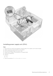
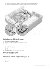
cover 7. Follow the procedure in After working inside your computer. Route the PSU cables through the retention clips. 4. Install the: a. Connect the PSU cables to the computer. 3. Close the front panel door. 6. Installing power supply unit (PSU) Steps 1. Insert the PSU into the PSU slot and slide it toward the back of the computer until it clicks into place. 2. bezel b. Removing and installing components 27 Tighten the screws to secure the PSU to the connectors on the system board. 5.
cover 7. Follow the procedure in After working inside your computer. Route the PSU cables through the retention clips. 4. Install the: a. Connect the PSU cables to the computer. 3. Close the front panel door. 6. Installing power supply unit (PSU) Steps 1. Insert the PSU into the PSU slot and slide it toward the back of the computer until it clicks into place. 2. bezel b. Removing and installing components 27 Tighten the screws to secure the PSU to the connectors on the system board. 5.
Tower Owners Manual
Page 62
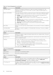
...The system does not skip any steps in OS environment. Table 16. Allows the system to power on by special WLAN signals. This option is set to AC power supply. ● Disabled - This option is enabled by default. Manageability Option USB provision MEBx Hotkey ...This option can utilize the additional hardware capabilities provided by default Wake on LAN/WWAN This option allows the computer to be powered on by bypassing some compatibility steps: ● Minimal - This option is disabled by default. Virtualization Support Option Description Virtualization...
...The system does not skip any steps in OS environment. Table 16. Allows the system to power on by special WLAN signals. This option is set to AC power supply. ● Disabled - This option is enabled by default. Manageability Option USB provision MEBx Hotkey ...This option can utilize the additional hardware capabilities provided by default Wake on LAN/WWAN This option allows the computer to be powered on by bypassing some compatibility steps: ● Minimal - This option is disabled by default. Virtualization Support Option Description Virtualization...
Tower Owners Manual
Page 71
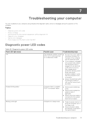
... of the computer. Topics: • Diagnostic power LED codes • Power LED issue • Dell Enhanced Pre-Boot System Assessment (ePSA) diagnostic 3.0 • Diagnostic error messages • System error messages • Power Supply Unit PSU Built-in off or is connected to verify that the power strip is plugged into a power strip, ensure that the computer turns...
... of the computer. Topics: • Diagnostic power LED codes • Power LED issue • Dell Enhanced Pre-Boot System Assessment (ePSA) diagnostic 3.0 • Diagnostic error messages • System error messages • Power Supply Unit PSU Built-in off or is connected to verify that the power strip is plugged into a power strip, ensure that the computer turns...
Tower Owners Manual
Page 76
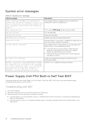
... steps for the same error. The failed component can now be performed by simply connecting the AC power cord to the PSU. Previous attempts at booting this checkpoint and contact Dell Technical Support The computer failed to the PSU. ● If the LED stays on for 15 ...to complete the boot routine three consecutive times for other device. 76 Troubleshooting your computer Dell recommends that the PSU is correct. Power Supply Unit PSU Built-in Self Test BIST This system supports a new Power Supply Unit (PSU) Built-in resolving this problem, please note this system have failed at...
... steps for the same error. The failed component can now be performed by simply connecting the AC power cord to the PSU. Previous attempts at booting this checkpoint and contact Dell Technical Support The computer failed to the PSU. ● If the LED stays on for 15 ...to complete the boot routine three consecutive times for other device. 76 Troubleshooting your computer Dell recommends that the PSU is correct. Power Supply Unit PSU Built-in Self Test BIST This system supports a new Power Supply Unit (PSU) Built-in resolving this problem, please note this system have failed at...
Tower Owners Manual
Page 78
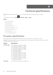
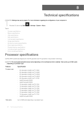
...processor type. Total cache up to 8 MB cache depending on processor type 78 Technical specifications Processor specifications OptiPlex 5050 systems are shipped with Intel 6th generation and 7th generation core processor technology. Feature Processor type Specification &#...8226; Audio specifications • Communication specifications • Storage specifications • Ports and connectors specifications • Power supply specifications • Physical dimension specifications • System board layout • Controls and lights specifications • Environmental specifications > Settings > ...
...processor type. Total cache up to 8 MB cache depending on processor type 78 Technical specifications Processor specifications OptiPlex 5050 systems are shipped with Intel 6th generation and 7th generation core processor technology. Feature Processor type Specification &#...8226; Audio specifications • Communication specifications • Storage specifications • Ports and connectors specifications • Power supply specifications • Physical dimension specifications • System board layout • Controls and lights specifications • Environmental specifications > Settings > ...
Tower Owners Manual
Page 81
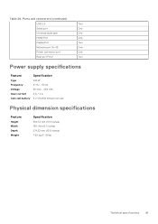
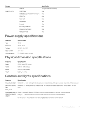
Ports and connectors (continued) USB 2.0 Two Serial port One Universal audio jack One HDMI Port One DisplayPort Two Network port RJ-45 One Power connector port One Rear port PS/2 Two Power supply specifications Feature Specification Type 240 W Frequency 47 Hz - 63 Hz Voltage 90 VAC - 264 VAC Input current 4 A / 2 A Coin cell battery 3 V CR2032...
Ports and connectors (continued) USB 2.0 Two Serial port One Universal audio jack One HDMI Port One DisplayPort Two Network port RJ-45 One Power connector port One Rear port PS/2 Two Power supply specifications Feature Specification Type 240 W Frequency 47 Hz - 63 Hz Voltage 90 VAC - 264 VAC Input current 4 A / 2 A Coin cell battery 3 V CR2032...
Tower Owners Manual
Page 83
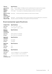
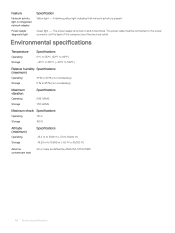
...) - A blinking yellow light indicates that network activity is functional. Network activity light on integrated network adapter : Green - Power supply Green light - The power cable must be connected to 35,000 ft) Airborne G2 or lower as defined by ANSI/ISA-S71.04-1985 contaminant level... Technical specifications 83 The power supply is turned on and is present. Environmental specifications Temperature Operating Storage Specifications 0°C to 35°C (32°F to 95...
...) - A blinking yellow light indicates that network activity is functional. Network activity light on integrated network adapter : Green - Power supply Green light - The power cable must be connected to 35,000 ft) Airborne G2 or lower as defined by ANSI/ISA-S71.04-1985 contaminant level... Technical specifications 83 The power supply is turned on and is present. Environmental specifications Temperature Operating Storage Specifications 0°C to 35°C (32°F to 95...
Small Form Factor Owners Manual
Page 4
... SD card reader...24 Removing the SD card reader...24 Installing the SD card reader...25 Power supply unit...25 Removing power supply unit (PSU)...25 Installing the power supply unit (PSU)...28 Power switch...28 Removing power switch...28 Installing the power switch...29 System board...30 Removing system board...30 Installing the system board...33 System board... password 47 Deleting or changing an existing system and/or setup password 48 System Setup options...48 Updating the BIOS in Windows ...54 Enabling smart power on...55 4 Contents
... SD card reader...24 Removing the SD card reader...24 Installing the SD card reader...25 Power supply unit...25 Removing power supply unit (PSU)...25 Installing the power supply unit (PSU)...28 Power switch...28 Removing power switch...28 Installing the power switch...29 System board...30 Removing system board...30 Installing the system board...33 System board... password 47 Deleting or changing an existing system and/or setup password 48 System Setup options...48 Updating the BIOS in Windows ...54 Enabling smart power on...55 4 Contents
Small Form Factor Owners Manual
Page 5
... specifications...64 Processor specifications...64 Memory specifications...65 Video specifications...65 Audio specifications...65 Communication specifications...66 Storage specifications...66 Ports and connectors specifications...66 Power supply specifications...67 Physical dimension specifications...67 Controls and lights specifications...67 Environmental specifications...68 9 Contacting...
... specifications...64 Processor specifications...64 Memory specifications...65 Video specifications...65 Audio specifications...65 Communication specifications...66 Storage specifications...66 Ports and connectors specifications...66 Power supply specifications...67 Physical dimension specifications...67 Controls and lights specifications...67 Environmental specifications...68 9 Contacting...
Small Form Factor Owners Manual
Page 25
Power supply unit Removing power supply unit (PSU) 1 Follow the procedure in After working inside your computer. 2 Remove the: a cover Removing and installing components 25 b Remove the screws that secure the ... procedure in Before working inside your computer. Installing the SD card reader 1 Place the SD card reader on the SD card reader enclosure [1]. a Release the power supply unit cables from the retention clips on the chassis. 2 Tighten the screws that secure the SD card reader and lift it away from the computer [2] [3].
Power supply unit Removing power supply unit (PSU) 1 Follow the procedure in After working inside your computer. 2 Remove the: a cover Removing and installing components 25 b Remove the screws that secure the ... procedure in Before working inside your computer. Installing the SD card reader 1 Place the SD card reader on the SD card reader enclosure [1]. a Release the power supply unit cables from the retention clips on the chassis. 2 Tighten the screws that secure the SD card reader and lift it away from the computer [2] [3].
Small Form Factor Owners Manual
Page 28
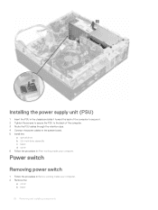
... 1 Follow the procedure in After working inside your computer. 2 Remove the: a cover b bezel 28 Removing and installing components Installing the power supply unit (PSU) 1 Insert the PSU in the chassis and slide it toward the back of the computer to secure it. 2 Tighten the screws to ...secure the PSU to the back of the computer. 3 Route the PSU cables through the retention clips. 4 Connect the power cables to the system board. 5 Install the: a optical drive b 2.5-inch drive assembly c bezel d cover 6 Follow the procedure in Before working inside your computer...
... 1 Follow the procedure in After working inside your computer. 2 Remove the: a cover b bezel 28 Removing and installing components Installing the power supply unit (PSU) 1 Insert the PSU in the chassis and slide it toward the back of the computer to secure it. 2 Tighten the screws to ...secure the PSU to the back of the computer. 3 Route the PSU cables through the retention clips. 4 Connect the power cables to the system board. 5 Install the: a optical drive b 2.5-inch drive assembly c bezel d cover 6 Follow the procedure in Before working inside your computer...

Small Form Factor Owners Manual
Page 53
... operating system supports Simple Boot Flag). Allows the system to enable or disable the keyboard error reporting when the computer starts. Allows you to be powered on by special LAN or wireless LAN signals. • LAN Only - Description Allows you to enable the USB devices to determine the speed of Intel... on LAN/WWAN Block Sleep Intel Ready Mode Table 13. POST Behavior Option Numlock LED Keyboard Errors Fast Boot Table 14. Allows you to AC power supply. • Disabled - This option is connected to enable or disable the Numlock feature when your computer starts.
... operating system supports Simple Boot Flag). Allows the system to enable or disable the keyboard error reporting when the computer starts. Allows you to be powered on by special LAN or wireless LAN signals. • LAN Only - Description Allows you to enable the USB devices to determine the speed of Intel... on LAN/WWAN Block Sleep Intel Ready Mode Table 13. POST Behavior Option Numlock LED Keyboard Errors Fast Boot Table 14. Allows you to AC power supply. • Disabled - This option is connected to enable or disable the Numlock feature when your computer starts.
Small Form Factor Owners Manual
Page 64
...; Video specifications • Audio specifications • Communication specifications • Storage specifications • Ports and connectors specifications • Power supply specifications • Physical dimension specifications • Controls and lights specifications • Environmental specifications Processor specifications OptiPlex 5050 systems are shipped with Intel 6th generation and 7th generation core processor technology. Feature Specification Processor type •...
...; Video specifications • Audio specifications • Communication specifications • Storage specifications • Ports and connectors specifications • Power supply specifications • Physical dimension specifications • Controls and lights specifications • Environmental specifications Processor specifications OptiPlex 5050 systems are shipped with Intel 6th generation and 7th generation core processor technology. Feature Specification Processor type •...
Small Form Factor Owners Manual
Page 67
... Orange - Blinking white light indicates that the computer is not detecting a physical connection to the hard light drive. Solid white light indicates power-on Green - Technical specifications 67 the computer is reading data from or writing data to the network. a good 1000 Mbps connection exists between... port Rear port PS/2 Specification Two (one with PowerShare) Four Two One One Two One One One Two Power supply specifications Feature Specification Type 180 W Frequency 47 Hz - 63 Hz Voltage 90 VAC - 264 VAC Input current 3 A / 1.5 A Coin cell battery 3 V ...
... Orange - Blinking white light indicates that the computer is not detecting a physical connection to the hard light drive. Solid white light indicates power-on Green - Technical specifications 67 the computer is reading data from or writing data to the network. a good 1000 Mbps connection exists between... port Rear port PS/2 Specification Two (one with PowerShare) Four Two One One Two One One One Two Power supply specifications Feature Specification Type 180 W Frequency 47 Hz - 63 Hz Voltage 90 VAC - 264 VAC Input current 3 A / 1.5 A Coin cell battery 3 V ...
Small Form Factor Owners Manual
Page 68
... back of the computer) and the electrical outlet. A blinking yellow light indicates that network activity is functional. The power supply is turned on integrated network adapter Yellow light - Power supply diagnostic light Green light - The power cable must be connected to 35,000 ft) Airborne contaminant level G2 or lower as defined by ANSI/ISA...
... back of the computer) and the electrical outlet. A blinking yellow light indicates that network activity is functional. The power supply is turned on integrated network adapter Yellow light - Power supply diagnostic light Green light - The power cable must be connected to 35,000 ft) Airborne contaminant level G2 or lower as defined by ANSI/ISA...
Micro Owners Manual
Page 5
Storage specifications...51 Ports and connectors specifications...51 Power supply specifications...52 Physical dimension specifications...52 Controls and lights specifications...52 Environmental specifications...53 9 Contacting Dell...54 Contents 5
Storage specifications...51 Ports and connectors specifications...51 Power supply specifications...52 Physical dimension specifications...52 Controls and lights specifications...52 Environmental specifications...53 9 Contacting Dell...54 Contents 5


