
Tower Owners Manual
Page 2
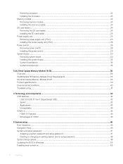
......22 Memory module...23 Removing memory module...23 Installing memory module...23 Expansion card...24 Removing PCIe expansion card...24 Installing PCIe expansion card...25 Power supply unit...26 Removing power supply unit (PSU)...26 Installing power supply unit (PSU)...27 2 Contents
......22 Memory module...23 Removing memory module...23 Installing memory module...23 Expansion card...24 Removing PCIe expansion card...24 Installing PCIe expansion card...25 Power supply unit...26 Removing power supply unit (PSU)...26 Installing power supply unit (PSU)...27 2 Contents
Tower Owners Manual
Page 4
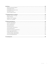
... 7: Troubleshooting your computer 71 Diagnostic power LED codes...71 Power LED issue...72 Dell Enhanced Pre-Boot System Assessment (ePSA) diagnostic 3.0 72 Running the ePSA Diagnostics...72 Diagnostic error messages...73 System error messages...76 Power Supply Unit PSU Built-in Self Test ...Audio specifications...79 Communication specifications...80 Storage specifications...80 Ports and connectors specifications...80 Power supply specifications...81 Physical dimension specifications...81 System board layout...82 Controls and lights specifications...82 Environmental specifications...83 Chapter ...
... 7: Troubleshooting your computer 71 Diagnostic power LED codes...71 Power LED issue...72 Dell Enhanced Pre-Boot System Assessment (ePSA) diagnostic 3.0 72 Running the ePSA Diagnostics...72 Diagnostic error messages...73 System error messages...76 Power Supply Unit PSU Built-in Self Test ...Audio specifications...79 Communication specifications...80 Storage specifications...80 Ports and connectors specifications...80 Power supply specifications...81 Physical dimension specifications...81 System board layout...82 Controls and lights specifications...82 Environmental specifications...83 Chapter ...
Tower Owners Manual
Page 9
... door • Storage • Optical drive • M.2 PCIe SSD • SD card reader • Memory module • Expansion card • Power supply unit • VGA daughter board • Intrusion switch • Power switch • Speaker • Coin cell battery • Heat sink assembly • Processor • System fan • System board Recommended tools...
... door • Storage • Optical drive • M.2 PCIe SSD • SD card reader • Memory module • Expansion card • Power supply unit • VGA daughter board • Intrusion switch • Power switch • Speaker • Coin cell battery • Heat sink assembly • Processor • System fan • System board Recommended tools...

Tower Owners Manual
Page 26
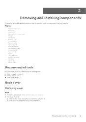
...: a. c. b. Remove the: a. Unroute the PSU cables from the computer [2]. 26 Removing and installing components Slide and lift the PSU away from the retention clip [4]. Power supply unit Removing power supply unit (PSU) Steps 1. Follow the procedure in Before working inside your computer. 2. Pull the release clip [3]. bezel 3. d. Press the release tab [1]. Disconnect the PSU...
...: a. c. b. Remove the: a. Unroute the PSU cables from the computer [2]. 26 Removing and installing components Slide and lift the PSU away from the retention clip [4]. Power supply unit Removing power supply unit (PSU) Steps 1. Follow the procedure in Before working inside your computer. 2. Pull the release clip [3]. bezel 3. d. Press the release tab [1]. Disconnect the PSU...
Tower Owners Manual
Page 27
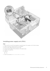
Close the front panel door. 6. Follow the procedure in After working inside your computer. cover 7. Tighten the screws to secure the PSU to the connectors on the system board. 5. bezel b. Route the PSU cables through the retention clips. 4. Connect the PSU cables to the computer. 3. Install the: a. Removing and installing components 27 Insert the PSU into the PSU slot and slide it toward the back of the computer until it clicks into place. 2. Installing power supply unit (PSU) Steps 1.
Close the front panel door. 6. Follow the procedure in After working inside your computer. cover 7. Tighten the screws to secure the PSU to the connectors on the system board. 5. bezel b. Route the PSU cables through the retention clips. 4. Connect the PSU cables to the computer. 3. Install the: a. Removing and installing components 27 Insert the PSU into the PSU slot and slide it toward the back of the computer until it clicks into place. 2. Installing power supply unit (PSU) Steps 1.
Tower Owners Manual
Page 62
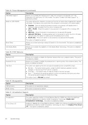
...- Virtualization Support Option Description Virtualization This option specifies whether a Virtual Machine Monitor (VMM) can speed up and immediately boot to be powered on by default. 62 System setup Enable VT for direct I /O Enables or disables the Virtual Machine Monitor (VMM) from the LAN...Fast Boot Description Allows you to enable the capability of Intel Ready Mode Technology. Power Management (continued) Option Description USB Wake Support Allows you to block entering to AC power supply. ● Disabled - Table 17. Does not allows the system to wake the...
...- Virtualization Support Option Description Virtualization This option specifies whether a Virtual Machine Monitor (VMM) can speed up and immediately boot to be powered on by default. 62 System setup Enable VT for direct I /O Enables or disables the Virtual Machine Monitor (VMM) from the LAN...Fast Boot Description Allows you to enable the capability of Intel Ready Mode Technology. Power Management (continued) Option Description USB Wake Support Allows you to block entering to AC power supply. ● Disabled - Table 17. Does not allows the system to wake the...
Tower Owners Manual
Page 71
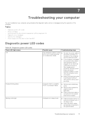
... and reinstall any cards. ● Remove and reinstall the graphics card, if applicable. ● Ensure the power cable is not receiving power the power connector on . Computer fails to bring the computer out of the computer and the electrical outlet. ● If...or in Self Test BIST Diagnostic power LED codes Table 25. Topics: • Diagnostic power LED codes • Power LED issue • Dell Enhanced Pre-Boot System Assessment (ePSA) diagnostic 3.0 • Diagnostic error messages • System error messages • Power Supply Unit PSU Built-in Hibernation mode...
... and reinstall any cards. ● Remove and reinstall the graphics card, if applicable. ● Ensure the power cable is not receiving power the power connector on . Computer fails to bring the computer out of the computer and the electrical outlet. ● If...or in Self Test BIST Diagnostic power LED codes Table 25. Topics: • Diagnostic power LED codes • Power LED issue • Dell Enhanced Pre-Boot System Assessment (ePSA) diagnostic 3.0 • Diagnostic error messages • System error messages • Power Supply Unit PSU Built-in Hibernation mode...
Tower Owners Manual
Page 76
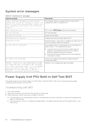
...failed. System fan failure System fan has failed. Dell recommends that the PSU is correct. A parameter out of range may or may not indicate a potential hard drive problem A chip on , it indicates that you back up your computer Power Supply Unit PSU Built-in Self Test BIST This system... supports a new Power Supply Unit (PSU) Built-in resolving this problem, please note this system have failed at checkpoint [nnnn]. Turn ...
...failed. System fan failure System fan has failed. Dell recommends that the PSU is correct. A parameter out of range may or may not indicate a potential hard drive problem A chip on , it indicates that you back up your computer Power Supply Unit PSU Built-in Self Test BIST This system... supports a new Power Supply Unit (PSU) Built-in resolving this problem, please note this system have failed at checkpoint [nnnn]. Turn ...
Tower Owners Manual
Page 78
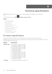
... • Storage specifications • Ports and connectors specifications • Power supply specifications • Physical dimension specifications • System board layout • Controls and lights specifications • Environmental specifications > Settings > System > About. Total cache up to 8 MB cache depending on processor type. Processor specifications OptiPlex 5050 systems are shipped with Intel 6th generation and 7th...
... • Storage specifications • Ports and connectors specifications • Power supply specifications • Physical dimension specifications • System board layout • Controls and lights specifications • Environmental specifications > Settings > System > About. Total cache up to 8 MB cache depending on processor type. Processor specifications OptiPlex 5050 systems are shipped with Intel 6th generation and 7th...
Tower Owners Manual
Page 81
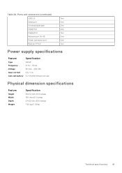
... and connectors (continued) USB 2.0 Two Serial port One Universal audio jack One HDMI Port One DisplayPort Two Network port RJ-45 One Power connector port One Rear port PS/2 Two Power supply specifications Feature Specification Type 240 W Frequency 47 Hz - 63 Hz Voltage 90 VAC - 264 VAC Input current 4 A / 2 A Coin cell battery 3 V CR2032...
... and connectors (continued) USB 2.0 Two Serial port One Universal audio jack One HDMI Port One DisplayPort Two Network port RJ-45 One Power connector port One Rear port PS/2 Two Power supply specifications Feature Specification Type 240 W Frequency 47 Hz - 63 Hz Voltage 90 VAC - 264 VAC Input current 4 A / 2 A Coin cell battery 3 V CR2032...
Tower Owners Manual
Page 83
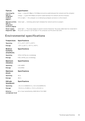
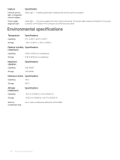
Off (no light) - Power supply Green light - The power supply is turned on and is present. Feature Specification Link integrity light on integrated network adapter Yellow light - A blinking yellow light indicates that network activity is ... -15.2 m to 30482000 m (-50 to 10,0006560 ft) -15.20 m to 10,668 m (-50 ft to diagnostic light the power connector (at the back of the computer) and the electrical outlet. The power cable must be connected to 35,000 ft) Airborne G2 or lower as defined by ANSI/ISA-S71.04...
Off (no light) - Power supply Green light - The power supply is turned on and is present. Feature Specification Link integrity light on integrated network adapter Yellow light - A blinking yellow light indicates that network activity is ... -15.2 m to 30482000 m (-50 to 10,0006560 ft) -15.20 m to 10,668 m (-50 ft to diagnostic light the power connector (at the back of the computer) and the electrical outlet. The power cable must be connected to 35,000 ft) Airborne G2 or lower as defined by ANSI/ISA-S71.04...
Small Form Factor Owners Manual
Page 4
... SD card reader...24 Removing the SD card reader...24 Installing the SD card reader...25 Power supply unit...25 Removing power supply unit (PSU)...25 Installing the power supply unit (PSU)...28 Power switch...28 Removing power switch...28 Installing the power switch...29 System board...30 Removing system board...30 Installing the system board...33 System board... password 47 Deleting or changing an existing system and/or setup password 48 System Setup options...48 Updating the BIOS in Windows ...54 Enabling smart power on...55 4 Contents
... SD card reader...24 Removing the SD card reader...24 Installing the SD card reader...25 Power supply unit...25 Removing power supply unit (PSU)...25 Installing the power supply unit (PSU)...28 Power switch...28 Removing power switch...28 Installing the power switch...29 System board...30 Removing system board...30 Installing the system board...33 System board... password 47 Deleting or changing an existing system and/or setup password 48 System Setup options...48 Updating the BIOS in Windows ...54 Enabling smart power on...55 4 Contents
Small Form Factor Owners Manual
Page 5
... specifications...64 Processor specifications...64 Memory specifications...65 Video specifications...65 Audio specifications...65 Communication specifications...66 Storage specifications...66 Ports and connectors specifications...66 Power supply specifications...67 Physical dimension specifications...67 Controls and lights specifications...67 Environmental specifications...68 9 Contacting...
... specifications...64 Processor specifications...64 Memory specifications...65 Video specifications...65 Audio specifications...65 Communication specifications...66 Storage specifications...66 Ports and connectors specifications...66 Power supply specifications...67 Physical dimension specifications...67 Controls and lights specifications...67 Environmental specifications...68 9 Contacting...
Small Form Factor Owners Manual
Page 25
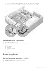
Power supply unit Removing power supply unit (PSU) 1 Follow the procedure in After working inside your computer. 2 Remove the: a cover Removing and installing components 25 Installing the SD card reader 1 Place ... to the computer. 3 Install the: a M.2 PCIe SSD b optical drive c 2.5-inch drive assembly d bezel e cover 4 Follow the procedure in Before working inside your computer. a Release the power supply unit cables from the computer [2] [3].
Power supply unit Removing power supply unit (PSU) 1 Follow the procedure in After working inside your computer. 2 Remove the: a cover Removing and installing components 25 Installing the SD card reader 1 Place ... to the computer. 3 Install the: a M.2 PCIe SSD b optical drive c 2.5-inch drive assembly d bezel e cover 4 Follow the procedure in Before working inside your computer. a Release the power supply unit cables from the computer [2] [3].
Small Form Factor Owners Manual
Page 28
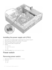
...the power supply unit (PSU) 1 Insert the PSU in the chassis and slide it toward the back of the computer to secure it. 2 Tighten the screws to secure the PSU to the back of the computer. 3 Route the PSU cables through the retention clips. 4 Connect the power ...cables to the system board. 5 Install the: a optical drive b 2.5-inch drive assembly c bezel d cover 6 Follow the procedure in Before working inside your computer. Power switch Removing power switch 1 Follow the procedure in After working inside your computer....
...the power supply unit (PSU) 1 Insert the PSU in the chassis and slide it toward the back of the computer to secure it. 2 Tighten the screws to secure the PSU to the back of the computer. 3 Route the PSU cables through the retention clips. 4 Connect the power ...cables to the system board. 5 Install the: a optical drive b 2.5-inch drive assembly c bezel d cover 6 Follow the procedure in Before working inside your computer. Power switch Removing power switch 1 Follow the procedure in After working inside your computer....

Small Form Factor Owners Manual
Page 53
... the controls when Deep Sleep is set to AC power supply. • Disabled - Allows you to sleep (S3 state) in S4 and S5 Allows you to enable the USB devices to wake the computer from standby (S1 / S3), Hibernate (S4), and Power Off (S5) modes. Description Allows you to block... when it receives a wake-up and immediately boot to enable or disable the keyboard error reporting when the computer starts. Allows the system to power up the boot process by bypassing some compatibility steps: • Minimal - This option is Disabled by default. Option Deep Sleep Control Fan Control...
... the controls when Deep Sleep is set to AC power supply. • Disabled - Allows you to sleep (S3 state) in S4 and S5 Allows you to enable the USB devices to wake the computer from standby (S1 / S3), Hibernate (S4), and Power Off (S5) modes. Description Allows you to block... when it receives a wake-up and immediately boot to enable or disable the keyboard error reporting when the computer starts. Allows the system to power up the boot process by bypassing some compatibility steps: • Minimal - This option is Disabled by default. Option Deep Sleep Control Fan Control...
Small Form Factor Owners Manual
Page 64
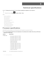
...; Video specifications • Audio specifications • Communication specifications • Storage specifications • Ports and connectors specifications • Power supply specifications • Physical dimension specifications • Controls and lights specifications • Environmental specifications Processor specifications OptiPlex 5050 systems are shipped with Intel 6th generation and 7th generation core processor technology. For more information regarding the...
...; Video specifications • Audio specifications • Communication specifications • Storage specifications • Ports and connectors specifications • Power supply specifications • Physical dimension specifications • Controls and lights specifications • Environmental specifications Processor specifications OptiPlex 5050 systems are shipped with Intel 6th generation and 7th generation core processor technology. For more information regarding the...
Small Form Factor Owners Manual
Page 67
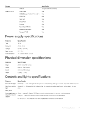
... port Rear port PS/2 Specification Two (one with PowerShare) Four Two One One Two One One One Two Power supply specifications Feature Specification Type 180 W Frequency 47 Hz - 63 Hz Voltage 90 VAC - 264 VAC Input current 3 A / 1.5 A Coin cell battery 3 V CR2032 lithium coin...Width 92.6 mm (3.65 inches) Depth 292 mm (11.50 inches) Weight 5.26 kg (11.57 lb) Controls and lights specifications Feature Specification Power button light White light - blinking white light indicates sleep state of the computer. a good 10 Mbps or 100 Mbps connection exists between the network and...
... port Rear port PS/2 Specification Two (one with PowerShare) Four Two One One Two One One One Two Power supply specifications Feature Specification Type 180 W Frequency 47 Hz - 63 Hz Voltage 90 VAC - 264 VAC Input current 3 A / 1.5 A Coin cell battery 3 V CR2032 lithium coin...Width 92.6 mm (3.65 inches) Depth 292 mm (11.50 inches) Weight 5.26 kg (11.57 lb) Controls and lights specifications Feature Specification Power button light White light - blinking white light indicates sleep state of the computer. a good 10 Mbps or 100 Mbps connection exists between the network and...
Small Form Factor Owners Manual
Page 68
Power supply diagnostic light Green light - The power supply is turned on integrated network adapter Yellow light - The power cable must be connected to 35,000 ft) Airborne contaminant level G2 or lower as defined by ANSI/ISA-S71.04-1985 68 Technical ... G Storage 160 G Altitude (maximum) Operating Storage Specifications -15.2 m to 3048 m (-50 to 10,000 ft) -15.20 m to 10,668 m (-50 ft to the power connector (at the back of the computer) and the electrical outlet. Feature Specification Network activity light on and is functional. A blinking yellow light indicates that...
Power supply diagnostic light Green light - The power supply is turned on integrated network adapter Yellow light - The power cable must be connected to 35,000 ft) Airborne contaminant level G2 or lower as defined by ANSI/ISA-S71.04-1985 68 Technical ... G Storage 160 G Altitude (maximum) Operating Storage Specifications -15.2 m to 3048 m (-50 to 10,000 ft) -15.20 m to 10,668 m (-50 ft to the power connector (at the back of the computer) and the electrical outlet. Feature Specification Network activity light on and is functional. A blinking yellow light indicates that...

Micro Owners Manual
Page 5
Storage specifications...51 Ports and connectors specifications...51 Power supply specifications...52 Physical dimension specifications...52 Controls and lights specifications...52 Environmental specifications...53 9 Contacting Dell...54 Contents 5
Storage specifications...51 Ports and connectors specifications...51 Power supply specifications...52 Physical dimension specifications...52 Controls and lights specifications...52 Environmental specifications...53 9 Contacting Dell...54 Contents 5


