
Quick Reference
Page 4
System Board Components 36 Replacing the Computer Cover 37 Mini Tower Computer 38 Front View 38 Back View 40 Back Panel Connectors 41 Removing the Computer Cover 43 Inside View of Your Computer 45 System Board Components 46 Replacing the Computer Cover 47 Solving Problems 47 Dell Diagnostics 48 Power Lights 51 Beep Codes 53 System Messages 54 Diagnostic Lights 56 Clearing Forgotten Passwords 60 Clearing CMOS Settings 62 Flashing the BIOS 63 Index 65 4 Contents
System Board Components 36 Replacing the Computer Cover 37 Mini Tower Computer 38 Front View 38 Back View 40 Back Panel Connectors 41 Removing the Computer Cover 43 Inside View of Your Computer 45 System Board Components 46 Replacing the Computer Cover 47 Solving Problems 47 Dell Diagnostics 48 Power Lights 51 Beep Codes 53 System Messages 54 Diagnostic Lights 56 Clearing Forgotten Passwords 60 Clearing CMOS Settings 62 Flashing the BIOS 63 Index 65 4 Contents
Quick Reference
Page 53
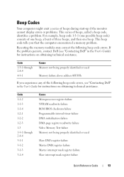
... beep code, identifies a problem. If the problem persists, contact Dell (see "Contacting Dell" in the User's Guide) for instructions on obtaining technical assistance. ...Code 1-1-2 1-1-3 1-1-4 1-2-1 1-2-2 1-2-3 1-3 1-3-1 through 2-4-4 4-3-1 Cause Memory not being properly identified or used Memory failure above address 0FFFFh If you that the computer encountered a memory problem. Code 1-3-1 through 2-4-4 3-1-1 3-1-2 3-1-3 3-1-4 Cause Microprocessor register failure NVRAM read/write failure ROM BIOS...
... beep code, identifies a problem. If the problem persists, contact Dell (see "Contacting Dell" in the User's Guide) for instructions on obtaining technical assistance. ...Code 1-1-2 1-1-3 1-1-4 1-2-1 1-2-2 1-2-3 1-3 1-3-1 through 2-4-4 4-3-1 Cause Memory not being properly identified or used Memory failure above address 0FFFFh If you that the computer encountered a memory problem. Code 1-3-1 through 2-4-4 3-1-1 3-1-2 3-1-3 3-1-4 Cause Microprocessor register failure NVRAM read/write failure ROM BIOS...
Quick Reference
Page 56
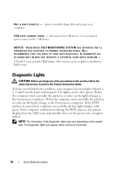
... instructions located in the Product Information Guide. This feature can be enabled or disabled in the process the computer halted. To help identify where in BIOS setup. When the computer starts normally, the patterns or codes on the lights change as the boot process completes. The lights can be off or... disk and restart your computer has four lights labeled 1, 2, 3, and 4 on the LEDs may vary depending on the lights change as the boot process completes. DELL RECOMMENDS THAT YOU BACK UP YOUR DATA REGULARLY. NOTICE -
... instructions located in the Product Information Guide. This feature can be enabled or disabled in the process the computer halted. To help identify where in BIOS setup. When the computer starts normally, the patterns or codes on the lights change as the boot process completes. The lights can be off or... disk and restart your computer has four lights labeled 1, 2, 3, and 4 on the LEDs may vary depending on the lights change as the boot process completes. DELL RECOMMENDS THAT YOU BACK UP YOUR DATA REGULARLY. NOTICE -
Quick Reference
Page 57
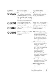
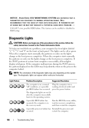
...Problem Description Suggested Resolution The computer is in a normal Plug the computer into your computer. • If the problem persists, contact Dell. A possible BIOS failure has occurred; Run the BIOS Recovery utility, wait for instructions on how to the operating system. A possible processor failure has Reinstall the processor and occurred. Quick ... without error. • If available, install properly working memory of the same type into a "off" condition, or a possible working electrical outlet and pre-BIOS failure has occurred. restart the computer. press the power button.
...Problem Description Suggested Resolution The computer is in a normal Plug the computer into your computer. • If the problem persists, contact Dell. A possible BIOS failure has occurred; Run the BIOS Recovery utility, wait for instructions on how to the operating system. A possible processor failure has Reinstall the processor and occurred. Quick ... without error. • If available, install properly working memory of the same type into a "off" condition, or a possible working electrical outlet and pre-BIOS failure has occurred. restart the computer. press the power button.
Quick Reference
Page 63
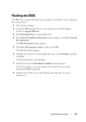
...Save In window appears. 6 Click the down arrow to disk, and then click OK. The file downloads to your computer at the Dell Support website at support.dell.com. 3 Click Download Now to download the file. 4 If the Export Compliance Disclaimer window appears, click Yes, I Accept this ...instructions. The File Download window appears. 5 Click Save this Agreement. Quick Reference Guide 63 Flashing the BIOS The BIOS may require flashing when an update is titled the same as the downloaded BIOS update file. 8 Double-click the file icon on the desktop and follow the on the computer. ...
...Save In window appears. 6 Click the down arrow to disk, and then click OK. The file downloads to your computer at the Dell Support website at support.dell.com. 3 Click Download Now to download the file. 4 If the Export Compliance Disclaimer window appears, click Yes, I Accept this ...instructions. The File Download window appears. 5 Click Save this Agreement. Quick Reference Guide 63 Flashing the BIOS The BIOS may require flashing when an update is titled the same as the downloaded BIOS update file. 8 Double-click the file icon on the desktop and follow the on the computer. ...

User's Guide
Page 5
... Entering System Setup 79 System Setup Screens 79 System Setup Options 80 Boot Sequence 88 Clearing Forgotten Passwords 91 Clearing CMOS Settings 92 Flashing the BIOS 93 About RAID Configurations 95 Verifying That RAID Is Working 95 RAID Level 1 Configuration 96 Troubleshooting RAID 96 Recovering From a Multiple Hard Drive Failure Using...
... Entering System Setup 79 System Setup Screens 79 System Setup Options 80 Boot Sequence 88 Clearing Forgotten Passwords 91 Clearing CMOS Settings 92 Flashing the BIOS 93 About RAID Configurations 95 Verifying That RAID Is Working 95 RAID Level 1 Configuration 96 Troubleshooting RAID 96 Recovering From a Multiple Hard Drive Failure Using...
User's Guide
Page 27
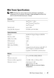
Processor Processor type Internal cache Front Side Bus frequency System Information Chipset Data bus width Address bus width DMA channels Interrupt levels BIOS chip (NVRAM) NIC Memory Type Memory connectors Memory modules supported Minimum memory Intel® Core™ 2 Duo Intel® Pentium® Dual Core Intel® ...
Processor Processor type Internal cache Front Side Bus frequency System Information Chipset Data bus width Address bus width DMA channels Interrupt levels BIOS chip (NVRAM) NIC Memory Type Memory connectors Memory modules supported Minimum memory Intel® Core™ 2 Duo Intel® Pentium® Dual Core Intel® ...
User's Guide
Page 28
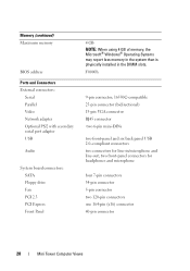
...-pin connector 5-pin connector two 120-pin connectors one 164-pin (x16) connector 40-pin connector 28 Mini Tower Computer Views Memory (continued) Maximum memory BIOS address Ports and Connectors External connectors: Serial Parallel Video Network adapter Optional PS/2 with secondary serial port adapter USB Audio System board connectors: SATA Floppy...
...-pin connector 5-pin connector two 120-pin connectors one 164-pin (x16) connector 40-pin connector 28 Mini Tower Computer Views Memory (continued) Maximum memory BIOS address Ports and Connectors External connectors: Serial Parallel Video Network adapter Optional PS/2 with secondary serial port adapter USB Audio System board connectors: SATA Floppy...
User's Guide
Page 39
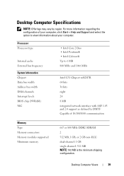
.... Desktop Computer Views 39 Processor Processor type Internal cache External bus frequency System Information Chipset Data bus width Address bus width DMA channels Interrupt levels BIOS chip (NVRAM) NIC • Intel Core 2 Duo • Intel Pentium® • Intel Celeron® Up to view information about your computer...
.... Desktop Computer Views 39 Processor Processor type Internal cache External bus frequency System Information Chipset Data bus width Address bus width DMA channels Interrupt levels BIOS chip (NVRAM) NIC • Intel Core 2 Duo • Intel Pentium® • Intel Celeron® Up to view information about your computer...
User's Guide
Page 66
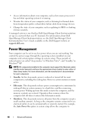
... remains active. • Hibernate. • Access information about Dell OpenManage Client Instrumentation, see the manufacturer's documentation for each component. • Standby. These periods of these sleep modes. As long as updating its BIOS or shutting it is running. • Monitor the status of... A managed system is reduced or turned off when it can be automatically or remotely started. For more information, see the Dell OpenManage Client Instrumentation User's Guide available on a network that uses IT Assistant. This sleep mode reduces power consumption to a minimum...
... remains active. • Hibernate. • Access information about Dell OpenManage Client Instrumentation, see the manufacturer's documentation for each component. • Standby. These periods of these sleep modes. As long as updating its BIOS or shutting it is running. • Monitor the status of... A managed system is reduced or turned off when it can be automatically or remotely started. For more information, see the Dell OpenManage Client Instrumentation User's Guide available on a network that uses IT Assistant. This sleep mode reduces power consumption to a minimum...
User's Guide
Page 80
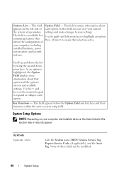
.... Press to expand or collapse each option. As an option is a scrollable list containing features that selection active. System System Info Lists the System name, BIOS Version, Service Tag, Express Service Code, (if applicable), and the Asset Tag.
.... Press to expand or collapse each option. As an option is a scrollable list containing features that selection active. System System Info Lists the System name, BIOS Version, Service Tag, Express Service Code, (if applicable), and the Asset Tag.
User's Guide
Page 85
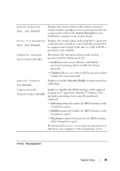
...password to be purchased separately. • Activate permanently enables the BIOS interface of the Computrace agent. • Disable permanently disables the BIOS interface of the Computrace agent. • Deactivate temporarily deactivates the BIOS interface of the Computrace agent. If the drive is a CD ...or DVD, a password is not available. This optional monitoring service must be assigned and verified. Computrace(R) (Deactivate default) Enables or disables the BIOS interface of the ...
...password to be purchased separately. • Activate permanently enables the BIOS interface of the Computrace agent. • Disable permanently disables the BIOS interface of the Computrace agent. • Deactivate temporarily deactivates the BIOS interface of the Computrace agent. If the drive is a CD ...or DVD, a password is not available. This optional monitoring service must be assigned and verified. Computrace(R) (Deactivate default) Enables or disables the BIOS interface of the ...
User's Guide
Page 87
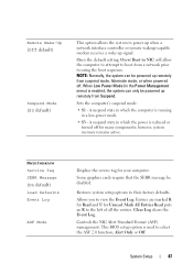
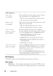
... computer's suspend mode. • S1 - Maintenance Service Tag SERR Message (On default) Load Defaults Event Log ASF Mode Displays the service tag for Unread. This BIOS setup option is enabled, the system can be disabled. Controls the NIC Alert Standard Format (ASF) management. On is reduced or turned off . NOTE: Normally...
... computer's suspend mode. • S1 - Maintenance Service Tag SERR Message (On default) Load Defaults Event Log ASF Mode Displays the service tag for Unread. This BIOS setup option is enabled, the system can be disabled. Controls the NIC Alert Standard Format (ASF) management. On is reduced or turned off . NOTE: Normally...
User's Guide
Page 88
...(F12=Boot Menu). • None displays no operating system is required to boot from the USB device. No steps are skipped during POST, the BIOS will display the error message and prompt you to Report (enabled) and an error is detected during computer startup. • On - Determines the ... by bypassing some compatibility steps. • Off - When set to Do Not Report (disabled) and an error is detected during POST, the BIOS will display the error message and continue booting the system. When set to change the boot sequence for devices. The system starts more quickly. If...
...(F12=Boot Menu). • None displays no operating system is required to boot from the USB device. No steps are skipped during POST, the BIOS will display the error message and prompt you to Report (enabled) and an error is detected during computer startup. • On - Determines the ... by bypassing some compatibility steps. • Off - When set to Do Not Report (disabled) and an error is detected during POST, the BIOS will display the error message and continue booting the system. When set to change the boot sequence for devices. The system starts more quickly. If...

User's Guide
Page 93
... file. 8 Double-click the file icon on the desktop and follow the on the computer. 2 Locate the BIOS update file for your computer at the Dell Support website at support.dell.com. 3 Click Download Now to electrical outlets, and turn them on page 323). The file downloads to your computer and devices to...
... file. 8 Double-click the file icon on the desktop and follow the on the computer. 2 Locate the BIOS update file for your computer at the Dell Support website at support.dell.com. 3 Click Download Now to electrical outlets, and turn them on page 323). The file downloads to your computer and devices to...

User's Guide
Page 103
Code 1-1-4 1-2-1 1-2-2 1-2-3 1-3 1-3-1 through 2-4-4 3-1-1 3-1-2 3-1-3 3-1-4 3-2-2 3-2-4 3-3-1 3-3-2 3-3-4 3-4-1 3-4-2 3-4-3 4-2-1 4-2-2 4-2-3 4-2-4 4-3-1 4-3-3 4-3-4 4-4-1 4-4-2 Cause ROM BIOS checksum failure Programmable interval timer failure DMA initialization failure DMA page register read/write failure Video Memory Test failure Memory not being properly identified or ...
Code 1-1-4 1-2-1 1-2-2 1-2-3 1-3 1-3-1 through 2-4-4 3-1-1 3-1-2 3-1-3 3-1-4 3-2-2 3-2-4 3-3-1 3-3-2 3-3-4 3-4-1 3-4-2 3-4-3 4-2-1 4-2-2 4-2-3 4-2-4 4-3-1 4-3-3 4-3-4 4-4-1 4-4-2 Cause ROM BIOS checksum failure Programmable interval timer failure DMA initialization failure DMA page register read/write failure Video Memory Test failure Memory not being properly identified or ...
User's Guide
Page 106
DELL RECOMMENDS THAT YOU BACK UP YOUR DATA REGULARLY. The lights can be enabled or disabled in BIOS setup. press the power button. S.M.A.R.T error, possible HDD failure. To help identify where in the Product Information Guide. If the POST portion of ..., the pattern displayed on the front or back panel. The diagnostic lights can be off " condition, or a possible working electrical outlet and pre-BIOS failure has occurred. HARD DRIVE SELF MONITORING SYSTEM HAS REPORTED THAT A PARAMETER HAS EXCEEDED ITS NORMAL OPERATING RANGE. This feature can appear either vertical or...
DELL RECOMMENDS THAT YOU BACK UP YOUR DATA REGULARLY. The lights can be enabled or disabled in BIOS setup. press the power button. S.M.A.R.T error, possible HDD failure. To help identify where in the Product Information Guide. If the POST portion of ..., the pattern displayed on the front or back panel. The diagnostic lights can be off " condition, or a possible working electrical outlet and pre-BIOS failure has occurred. HARD DRIVE SELF MONITORING SYSTEM HAS REPORTED THAT A PARAMETER HAS EXCEEDED ITS NORMAL OPERATING RANGE. This feature can appear either vertical or...
User's Guide
Page 143
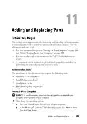
...Your Computer" on page 143 and "Before Working Inside Your Computer" on page 144. • You have read the safety information in the Dell™ Product Information Guide. • A component can be replaced or-if purchased separately-installed by performing the removal procedure in your computer.... assumes that the following tools: • Small flat-blade screwdriver • Small Phillips screwdriver • Small plastic scribe • Flash BIOS update program CD Turning Off Your Computer NOTICE: To avoid losing data, save and close all open files and exit all open programs before...
...Your Computer" on page 143 and "Before Working Inside Your Computer" on page 144. • You have read the safety information in the Dell™ Product Information Guide. • A component can be replaced or-if purchased separately-installed by performing the removal procedure in your computer.... assumes that the following tools: • Small flat-blade screwdriver • Small Phillips screwdriver • Small plastic scribe • Flash BIOS update program CD Turning Off Your Computer NOTICE: To avoid losing data, save and close all open files and exit all open programs before...

User's Guide
Page 271
... to be used for video-related tasks. AHCI - alert standards format - The length of the faster interface between the computer hardware and the operating system. BIOS - An interface for a SATA hard drive Host Controller which a portable computer battery is designed to enable technologies such as an interface between the video circuitry...
... to be used for video-related tasks. AHCI - alert standards format - The length of the faster interface between the computer hardware and the operating system. BIOS - An interface for a SATA hard drive Host Controller which a portable computer battery is designed to enable technologies such as an interface between the video circuitry...

User's Guide
Page 281
... primary temporary storage area for Management) standard that allows networked computers that interprets and executes program instructions. A text file included with existing hardware if the BIOS, operating system, and all devices are recharged (sometimes also referred to as the number of pixels across by the... BIOS, that have read -only - readme file - The higher the refresh rate, the less video flicker can be configured and started remotely. Typically, readme files provide ...
... primary temporary storage area for Management) standard that allows networked computers that interprets and executes program instructions. A text file included with existing hardware if the BIOS, operating system, and all devices are recharged (sometimes also referred to as the number of pixels across by the... BIOS, that have read -only - readme file - The higher the refresh rate, the less video flicker can be configured and started remotely. Typically, readme files provide ...


