
User Guide
Page 28
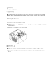
... during normal operation. Rotate the heat sink assembly upward, and remove the assembly from under the center cover latch on the socket. You can do so by sliding the release lever from the computer. 1 heat sink assembly 2 captive screw housing (2) NOTICE... in Before You Begin. 2. Back to Contents Page Processor Dell™ OptiPlex™ 320 User's Guide Removing the Processor Installing the Processor CAUTION: Before you begin any of your body before you replace the processor. 4. Removing the Processor 1. Follow the procedures in the Product Information Guide. Then...
... during normal operation. Rotate the heat sink assembly upward, and remove the assembly from under the center cover latch on the socket. You can do so by sliding the release lever from the computer. 1 heat sink assembly 2 captive screw housing (2) NOTICE... in Before You Begin. 2. Back to Contents Page Processor Dell™ OptiPlex™ 320 User's Guide Removing the Processor Installing the Processor CAUTION: Before you begin any of your body before you replace the processor. 4. Removing the Processor 1. Follow the procedures in the Product Information Guide. Then...

User Guide
Page 29
... properly with the front and rear alignment- notches on the socket. 5. If the release lever on the socket is ready for the new processor. Align the pin-1 corners of the processor and socket. 1 processor cover 6 release lever 2 tab 7 front alignment-notch 3 processor 8 socket and processor pin-1 indicator 4 processor socket 9 rear alignment-notch 5 center cover latch NOTICE: To avoid damage, ensure that...
... properly with the front and rear alignment- notches on the socket. 5. If the release lever on the socket is ready for the new processor. Align the pin-1 corners of the processor and socket. 1 processor cover 6 release lever 2 tab 7 front alignment-notch 3 processor 8 socket and processor pin-1 indicator 4 processor socket 9 rear alignment-notch 5 center cover latch NOTICE: To avoid damage, ensure that...

User Guide
Page 30
... assembly 2 heat-sink assembly bracket 3 captive screw housing (2) 12. Pivot the socket release lever back toward the socket, and snap it into place to Contents Page b. Clean the thermal grease from the bottom of the processor. 11. Apply the new thermal grease to the top of the heat sink. ... the heat sink assembly: a. Replace the computer cover (see Replacing the Computer Cover). NOTICE: Ensure that the tab on the processor cover is positioned underneath the center cover latch on the socket. 8. Back to secure the processor. 9. Ensure that you apply new thermal grease.
... assembly 2 heat-sink assembly bracket 3 captive screw housing (2) 12. Pivot the socket release lever back toward the socket, and snap it into place to Contents Page b. Clean the thermal grease from the bottom of the processor. 11. Apply the new thermal grease to the top of the heat sink. ... the heat sink assembly: a. Replace the computer cover (see Replacing the Computer Cover). NOTICE: Ensure that the tab on the processor cover is positioned underneath the center cover latch on the socket. 8. Back to secure the processor. 9. Ensure that you apply new thermal grease.

User Guide
Page 79
... from the system board. 1 floppy drive 2 CD/DVD drive 3 power supply 4 system board 5 heat sink assembly 6 hard drive System Board Components 1 fan connector (FAN) 2 processor connector (CPU) 3 processor power connector (12VPOWER) 4 front-panel connector (FNT_PANEL) 5 memory module connectors (DIMM_1, DIMM_2) 10 internal buzzer (SPKR1) 11 password jumper (PSWD) 12 RTC reset jumper...
... from the system board. 1 floppy drive 2 CD/DVD drive 3 power supply 4 system board 5 heat sink assembly 6 hard drive System Board Components 1 fan connector (FAN) 2 processor connector (CPU) 3 processor power connector (12VPOWER) 4 front-panel connector (FNT_PANEL) 5 memory module connectors (DIMM_1, DIMM_2) 10 internal buzzer (SPKR1) 11 password jumper (PSWD) 12 RTC reset jumper...
User Guide
Page 85
...it from under the center cover latch on each side of the heat sink assembly. Loosen the captive screw on the socket. Be sure that it has had sufficient time to cool before you touch any of the procedures in this section, ... captive screw housings (2) NOTICE: Unless a new heatsink is required for the new processor, reuse the original heat sink assembly when you replace the processor. 4. Back to Contents Page Processor Dell™ OptiPlex™ 320 User's Guide Removing the Processor Installing the Processor CAUTION: Before you begin any of your computer's electronic components.
...it from under the center cover latch on each side of the heat sink assembly. Loosen the captive screw on the socket. Be sure that it has had sufficient time to cool before you touch any of the procedures in this section, ... captive screw housings (2) NOTICE: Unless a new heatsink is required for the new processor, reuse the original heat sink assembly when you replace the processor. 4. Back to Contents Page Processor Dell™ OptiPlex™ 320 User's Guide Removing the Processor Installing the Processor CAUTION: Before you begin any of your computer's electronic components.

User Guide
Page 86
... on the computer. 3. If the release lever on the socket is ready for the new processor. Follow the procedures in the release position so that position. 4. 1 center cover latch 2 processor cover 3 processor 4 socket 5 release lever NOTICE: When replacing the processor, do not touch any of the pins inside the socket or allow any objects to that the...
... on the computer. 3. If the release lever on the socket is ready for the new processor. Follow the procedures in the release position so that position. 4. 1 center cover latch 2 processor cover 3 processor 4 socket 5 release lever NOTICE: When replacing the processor, do not touch any of the pins inside the socket or allow any objects to that the...

User Guide
Page 87
...: Ensure that the heat sink assembly is positioned underneath the center cover latch on the socket. 8. Ensure that the tab on the processor cover is correctly seated and secure. 1 processor cover 6 release lever 2 tab 7 front alignment-notch 3 processor 8 socket and processor pin-1 indicator 4 processor socket 9 rear alignment-notch 5 center cover latch NOTICE: To avoid damage, ensure that the...
...: Ensure that the heat sink assembly is positioned underneath the center cover latch on the socket. 8. Ensure that the tab on the processor cover is correctly seated and secure. 1 processor cover 6 release lever 2 tab 7 front alignment-notch 3 processor 8 socket and processor pin-1 indicator 4 processor socket 9 rear alignment-notch 5 center cover latch NOTICE: To avoid damage, ensure that the...


