Quick Reference Guide
Page 3
... 16 Desktop Computer - Back-Panel Connectors 18 Removing the Computer Cover 19 Before You Begin 20 Mini Tower Computer 21 Desktop Computer 23 Inside Your Computer 24 Mini Tower Computer 24 Desktop Computer 27 Solving Problems 30 Dell Diagnostics 30 System Lights 33 Diagnostic Lights 34 Beep Codes 37 Resolving Software and Hardware Incompatibilities 38...
... 16 Desktop Computer - Back-Panel Connectors 18 Removing the Computer Cover 19 Before You Begin 20 Mini Tower Computer 21 Desktop Computer 23 Inside Your Computer 24 Mini Tower Computer 24 Desktop Computer 27 Solving Problems 30 Dell Diagnostics 30 System Lights 33 Diagnostic Lights 34 Beep Codes 37 Resolving Software and Hardware Incompatibilities 38...

Quick Reference Guide
Page 11
System Views Mini Tower Computer - Quick Reference Guide 11 Front View 1 2 3 10 4 9 5 6 7 8 1 location of Service Tag Use the Service Tag to identify your computer when you access the Dell Support website or call technical support. 2 CD/DVD drive Insert a CD or DVD (if supported) into this drive. 3 floppy drive Insert a floppy disk into this drive. 4 hard-drive activity light This light flickers when the hard drive is in use.
System Views Mini Tower Computer - Quick Reference Guide 11 Front View 1 2 3 10 4 9 5 6 7 8 1 location of Service Tag Use the Service Tag to identify your computer when you access the Dell Support website or call technical support. 2 CD/DVD drive Insert a CD or DVD (if supported) into this drive. 3 floppy drive Insert a floppy disk into this drive. 4 hard-drive activity light This light flickers when the hard drive is in use.

Quick Reference Guide
Page 13
Insert the power cable into this connector. Insert a padlock to open the computer cover. Quick Reference Guide 13 Mini Tower Computer - Back View 1 2 3 4 5 6 1 cover release latch 2 padlock ring 3 power connector This latch allows you to lock the computer cover.
Insert the power cable into this connector. Insert a padlock to open the computer cover. Quick Reference Guide 13 Mini Tower Computer - Back View 1 2 3 4 5 6 1 cover release latch 2 padlock ring 3 power connector This latch allows you to lock the computer cover.

Quick Reference Guide
Page 14
... 115-V position. NOTICE: In Japan the voltage-selection switch must be set the switch for any installed PCI and PCI Express cards. Mini Tower Computer - NOTE: The integrated parallel connector is not detecting a physical connection to the same address. If you have a USB printer,...location. 4 voltage selection switch Your computer is equipped with the AC power available in your online User's Guide. • Green - See "Mini Tower Computer - Also, ensure that most closely matches the AC power available in your location. 5 back-panel connectors Plug serial, USB, and other ...
... 115-V position. NOTICE: In Japan the voltage-selection switch must be set the switch for any installed PCI and PCI Express cards. Mini Tower Computer - NOTE: The integrated parallel connector is not detecting a physical connection to the same address. If you have a USB printer,...location. 4 voltage selection switch Your computer is equipped with the AC power available in your online User's Guide. • Green - See "Mini Tower Computer - Also, ensure that most closely matches the AC power available in your location. 5 back-panel connectors Plug serial, USB, and other ...

Quick Reference Guide
Page 21
Mini Tower Computer CAUTION: Before you begin any static electricity that could harm internal components. Quick Reference Guide 21 CAUTION: To guard against electrical shock, always unplug .... NOTICE: Before touching anything inside your computer from the hinge tabs and set it aside on page 27). 5 Remove the computer cover: • Remove the mini tower computer cover (see "Mini Tower Computer" on page 21). • Remove the desktop computer cover (see "Desktop Computer" on a soft nonabrasive surface.
Mini Tower Computer CAUTION: Before you begin any static electricity that could harm internal components. Quick Reference Guide 21 CAUTION: To guard against electrical shock, always unplug .... NOTICE: Before touching anything inside your computer from the hinge tabs and set it aside on page 27). 5 Remove the computer cover: • Remove the mini tower computer cover (see "Mini Tower Computer" on page 21). • Remove the desktop computer cover (see "Desktop Computer" on a soft nonabrasive surface.

User Guide
Page 6
... Drive This option enables or disables the floppy drive. Settings are Off, Internal, USB, and Read Only. (Internal default) Drive 0 through Drive 3 for the desktop, mini tower, and small form computers and Drive 0 though Drive 5 for the hard drives. This field appears below the Option Field and lists keys and their functions...
... Drive This option enables or disables the floppy drive. Settings are Off, Internal, USB, and Read Only. (Internal default) Drive 0 through Drive 3 for the desktop, mini tower, and small form computers and Drive 0 though Drive 5 for the hard drives. This field appears below the Option Field and lists keys and their functions...

User Guide
Page 13
...the socket or by prying off or unplugged from the electrical outlet for a few hours; The battery can operate your mini tower computer, see Entering System Setup). then reconnect the computer, turn it up out of the securing tabs at the negative... computer configuration, date, and time information. Remove the system battery. however, without a battery; Back to Contents Page Battery Dell™ OptiPlex™ 320 User's Guide CAUTION: Before you begin any of your computer's electronic components. Locate the battery socket (for your configuration information...
...the socket or by prying off or unplugged from the electrical outlet for a few hours; The battery can operate your mini tower computer, see Entering System Setup). then reconnect the computer, turn it up out of the securing tabs at the negative... computer configuration, date, and time information. Remove the system battery. however, without a battery; Back to Contents Page Battery Dell™ OptiPlex™ 320 User's Guide CAUTION: Before you begin any of your computer's electronic components. Locate the battery socket (for your configuration information...

User Guide
Page 16
... electrical shock, always unplug your computer and all attached devices from their electrical outlets, and then press the power button to Contents Page l For your mini tower computer, see: Removing the Computer Cover l For your computer, ground yourself by touching an unpainted metal surface, such as the metal at the back of...
... electrical shock, always unplug your computer and all attached devices from their electrical outlets, and then press the power button to Contents Page l For your mini tower computer, see: Removing the Computer Cover l For your computer, ground yourself by touching an unpainted metal surface, such as the metal at the back of...

User Guide
Page 19
... procedures in Before You Begin. 2. For a mini tower computer, see Back-Panel Connectors. 4. See Connecting Dual Monitors or a Monitor and a Television to a Graphics Card for more than one monitor (VGA or DVI) in addition to the television. Back to Contents Page Connecting Multiple Monitors Dell™ OptiPlex™ 320 User's Guide Before Connecting Mutiple Monitors...
... procedures in Before You Begin. 2. For a mini tower computer, see Back-Panel Connectors. 4. See Connecting Dual Monitors or a Monitor and a Television to a Graphics Card for more than one monitor (VGA or DVI) in addition to the television. Back to Contents Page Connecting Multiple Monitors Dell™ OptiPlex™ 320 User's Guide Before Connecting Mutiple Monitors...

User Guide
Page 50
...and support for components, such as memory, the hard drive, and the operating system l Customer Care - l Use the Service Tag (see mini tower Front View or desktop Front View) to identify your computer when you use Windows XP l How to work with programs and files l How ... - Click the topic that describes your configuration. l Enter the Express Service Code to direct your region or business segment to use support.dell.com or contact support. DSS is already installed on the screen. Windows Help and Support Center 1. Follow the instructions on your selections. ...
...and support for components, such as memory, the hard drive, and the operating system l Customer Care - l Use the Service Tag (see mini tower Front View or desktop Front View) to identify your computer when you use Windows XP l How to work with programs and files l How ... - Click the topic that describes your configuration. l Enter the Express Service Code to direct your region or business segment to use support.dell.com or contact support. DSS is already installed on the screen. Windows Help and Support Center 1. Follow the instructions on your selections. ...

User Guide
Page 72
...If the total installed computer memory is equal to or greater than that require address space. Back to Contents Page Memory Dell™ OptiPlex™ 320 User's Guide DDR2 Memory Overview Addressing Memory With 4-GB Configurations (32-bit Operating Systems Only) Removing Memory Installing Memory... indicated on the type of memory supported by your computer, see the "Memory" section of the specifications for your computer: l Mini Tower Computer Specifications l Desktop Computer Specifications NOTICE: Before you use a 64-bit operating system, the entire memory range is available to the...
...If the total installed computer memory is equal to or greater than that require address space. Back to Contents Page Memory Dell™ OptiPlex™ 320 User's Guide DDR2 Memory Overview Addressing Memory With 4-GB Configurations (32-bit Operating Systems Only) Removing Memory Installing Memory... indicated on the type of memory supported by your computer, see the "Memory" section of the specifications for your computer: l Mini Tower Computer Specifications l Desktop Computer Specifications NOTICE: Before you use a 64-bit operating system, the entire memory range is available to the...

User Guide
Page 74
... module 3 notch 4 crossbar NOTICE: To avoid damage to each end of System Memory to enter system setup and check the value for mini towers, see Dell Diagnostics). When the System Memory total is incorrect, turn off and disconnect your computer and devices from their sockets. If the memory total is... clips snap into position. The computer should have changed . Strike the F1 key to continue, F2 to Contents Page Run the Dell Diagnostics to verify that the memory modules are operating properly (see Removing the Computer Cover) and check the installed memory modules to ensure...
... module 3 notch 4 crossbar NOTICE: To avoid damage to each end of System Memory to enter system setup and check the value for mini towers, see Dell Diagnostics). When the System Memory total is incorrect, turn off and disconnect your computer and devices from their sockets. If the memory total is... clips snap into position. The computer should have changed . Strike the F1 key to continue, F2 to Contents Page Run the Dell Diagnostics to verify that the memory modules are operating properly (see Removing the Computer Cover) and check the installed memory modules to ensure...

User Guide
Page 75
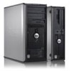
... the ENERGY STAR guidelines for property damage, personal injury, or death. ENERGY STAR is subject to avoid the problem. Dell Inc. Dell™ OptiPlex™ 320 User's Guide Mini Tower Computer About Your Computer Finding Information Mini Tower Computer Mini Tower Computer Specifications Advanced Features Cleaning Your Computer Connecting Multiple Monitors Reinstalling Drivers and the Operating System Solving Problems Microsoft...
... the ENERGY STAR guidelines for property damage, personal injury, or death. ENERGY STAR is subject to avoid the problem. Dell Inc. Dell™ OptiPlex™ 320 User's Guide Mini Tower Computer About Your Computer Finding Information Mini Tower Computer Mini Tower Computer Specifications Advanced Features Cleaning Your Computer Connecting Multiple Monitors Reinstalling Drivers and the Operating System Solving Problems Microsoft...

User Guide
Page 76
...blinks or remains solid to indicate Instead, perform an operating system shutdown. 8 power light NOTICE: If your computer when you access the Dell Support website or call technical support. 2 CD/DVD drive Insert a CD or DVD (if supported) into this drive. 3 floppy drive...light flickers when the hard drive is recommended that you use . Back to Contents Page Mini Tower Computer Dell™ OptiPlex™ 320 User's Guide About Your Mini Tower Computer Inside Your Computer About Your Mini Tower Computer Front View 1 location of Service Tag Use the Service Tag to identify your operating...
...blinks or remains solid to indicate Instead, perform an operating system shutdown. 8 power light NOTICE: If your computer when you access the Dell Support website or call technical support. 2 CD/DVD drive Insert a CD or DVD (if supported) into this drive. 3 floppy drive...light flickers when the hard drive is recommended that you use . Back to Contents Page Mini Tower Computer Dell™ OptiPlex™ 320 User's Guide About Your Mini Tower Computer Inside Your Computer About Your Mini Tower Computer Front View 1 location of Service Tag Use the Service Tag to identify your operating...

User Guide
Page 107
... integrated network interface capable of 10/100 communication: l Green - A good connection exists between a 10-Mbps network and the computer. Back to Contents Page Mini Tower Computer Specifications Dell™ OptiPlex™ 320 User's Guide Microprocessor Microprocessor type internal cache Memory Type Memory connectors Memory modules supported Minimum memory Maximum memory BIOS address Computer Information Chipset...
... integrated network interface capable of 10/100 communication: l Green - A good connection exists between a 10-Mbps network and the computer. Back to Contents Page Mini Tower Computer Specifications Dell™ OptiPlex™ 320 User's Guide Microprocessor Microprocessor type internal cache Memory Type Memory connectors Memory modules supported Minimum memory Maximum memory BIOS address Computer Information Chipset...
User Guide
Page 129
...from the system board. NOTICE: Before touching anything inside your computer from the electrical outlet before removing the cover. l For your mini tower computer, see Processor. 4. Slide the system board assembly toward the back of the computer. 2. Gently align the board into the... panel). 3. Remove any static electricity that you just removed next to the replacement system board to Contents Page System Board Dell™ OptiPlex™ 320 User's Guide Replacing the System Board Removing the System Board 1. CAUTION: To guard against the electrical shock, always unplug your...
...from the system board. NOTICE: Before touching anything inside your computer from the electrical outlet before removing the cover. l For your mini tower computer, see Processor. 4. Slide the system board assembly toward the back of the computer. 2. Gently align the board into the... panel). 3. Remove any static electricity that you just removed next to the replacement system board to Contents Page System Board Dell™ OptiPlex™ 320 User's Guide Replacing the System Board Removing the System Board 1. CAUTION: To guard against the electrical shock, always unplug your...


