
Quick Reference Guide
Page 20
.... Do not touch the components or contacts on the cable itself. Damage due to ground the system board. 4 If applicable, remove the computer stand (for instructions, see the documentation that is not authorized by Dell is not covered by your operating system, turn off your computer. 1 Shut down your warranty. Hold a component...
.... Do not touch the components or contacts on the cable itself. Damage due to ground the system board. 4 If applicable, remove the computer stand (for instructions, see the documentation that is not authorized by Dell is not covered by your operating system, turn off your computer. 1 Shut down your warranty. Hold a component...

Quick Reference Guide
Page 27
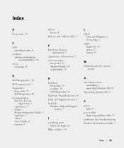
jumpered Desktop Computer unjumpered 2 1 3 4 6 5 1 drive bay (CD/DVD, floppy, 4 card slots and hard drive) 2 power supply 5 heat sink assembly 3 system board 6 front I/O panel Quick Reference Guide 27 The real-time clock is being reset (jumpered temporarily). Jumper PSWD Setting 1 RTCRST 1 Description Password features are disabled. Password features are enabled (default setting). The real-time clock has been enabled (default setting).
jumpered Desktop Computer unjumpered 2 1 3 4 6 5 1 drive bay (CD/DVD, floppy, 4 card slots and hard drive) 2 power supply 5 heat sink assembly 3 system board 6 front I/O panel Quick Reference Guide 27 The real-time clock is being reset (jumpered temporarily). Jumper PSWD Setting 1 RTCRST 1 Description Password features are disabled. Password features are enabled (default setting). The real-time clock has been enabled (default setting).

Quick Reference Guide
Page 33
... Diagnostic Lights to wake the computer. To exit the Dell Diagnostics and restart the computer, close the Main Menu screen. If the Dell Diagnostics is running a test, or a device on page 37. For information on contacting Dell, see "Beep Codes" on the system board may Check Diagnostic Lights to see if the specific problem...
... Diagnostic Lights to wake the computer. To exit the Dell Diagnostics and restart the computer, close the Main Menu screen. If the Dell Diagnostics is running a test, or a device on page 37. For information on contacting Dell, see "Beep Codes" on the system board may Check Diagnostic Lights to see if the specific problem...
Quick Reference Guide
Page 36
...a normal operating condition. 36 Quick Reference Guide For information on contacting Dell, see your computer. • If the problem persists, contact Dell. diagnostic lights turn green briefly before turning off to the system board from the hard drive, CD drive, and DVD drive. •...remove the modules, reinstall one memory module installed, reinstall it and restart the computer. A failure has occurred. For information on contacting Dell, see your online User's Guide. For information on reinstalling memory modules, see your online User's Guide. Continue until you have one...
...a normal operating condition. 36 Quick Reference Guide For information on contacting Dell, see your computer. • If the problem persists, contact Dell. diagnostic lights turn green briefly before turning off to the system board from the hard drive, CD drive, and DVD drive. •...remove the modules, reinstall one memory module installed, reinstall it and restart the computer. A failure has occurred. For information on contacting Dell, see your online User's Guide. For information on reinstalling memory modules, see your online User's Guide. Continue until you have one...
Quick Reference Guide
Page 43
See system board O operating system reinstalling, 6 reinstalling Windows XP, 39 Operating System CD, 6 P power light, 17 power light diagnosing problems with, 33 problems. See troubleshooting Product..., 38 cover removing, 19 E End User License Agreement, 5 ergonomics information, 5 error messages beep codes, 37 diagnostic lights, 34 system lights, 33 D Dell Diagnostics, 30 Dell support site, 7 diagnostics beep codes, 37 Dell Diagnostics, 30 documentation End User License Agreement, 5 ergonomics, 5 online, 7 Product Information Guide, 5 regulatory, 5 safety, 5 User's Guide, 6 warranty, 5 H ...
See system board O operating system reinstalling, 6 reinstalling Windows XP, 39 Operating System CD, 6 P power light, 17 power light diagnosing problems with, 33 problems. See troubleshooting Product..., 38 cover removing, 19 E End User License Agreement, 5 ergonomics information, 5 error messages beep codes, 37 diagnostic lights, 34 system lights, 33 D Dell Diagnostics, 30 Dell support site, 7 diagnostics beep codes, 37 Dell Diagnostics, 30 documentation End User License Agreement, 5 ergonomics, 5 online, 7 Product Information Guide, 5 regulatory, 5 safety, 5 User's Guide, 6 warranty, 5 H ...

Quick Reference Guide
Page 44
R regulatory information, 5 reinstalling Windows XP, 39 S safety instructions, 5 Service Tag, 6 software conflicts, 38 support website, 7 system board, 25, 28 System Restore, 38 U User's Guide, 6 W warranty information, 5 Windows XP Hardware Troubleshooter, 38 Help and Support Center, 7 reinstalling, 6, 39 setup, 41 System Restore, 38 T troubleshooting beep codes, 37 conflicts, 38 Dell Diagnostics, 30 diagnostic lights, 34 Hardware Troubleshooter, 38 Help and Support Center, 7 restore computer to previous operating state, 38 system lights, 33 44 Index
R regulatory information, 5 reinstalling Windows XP, 39 S safety instructions, 5 Service Tag, 6 software conflicts, 38 support website, 7 system board, 25, 28 System Restore, 38 U User's Guide, 6 W warranty information, 5 Windows XP Hardware Troubleshooter, 38 Help and Support Center, 7 reinstalling, 6, 39 setup, 41 System Restore, 38 T troubleshooting beep codes, 37 conflicts, 38 Dell Diagnostics, 30 diagnostic lights, 34 Hardware Troubleshooter, 38 Help and Support Center, 7 restore computer to previous operating state, 38 system lights, 33 44 Index

User Guide
Page 3
...password is not case-sensitive. The password setting changes to obtain and use up to Verify Password, followed by a jumper setting on the system board is in square brackets. 3. Typing Your System Password When you complete step 5. 1. If you leave your computer, they are not valid.... a jumper setting, anyone can only assign a system password when the following two options is assigned and the password jumper on the system board. Assigning a System Password To escape from the field without having a system password assigned, or if you have assigned an administrator password, the...
...password is not case-sensitive. The password setting changes to obtain and use up to Verify Password, followed by a jumper setting on the system board is in square brackets. 3. Typing Your System Password When you complete step 5. 1. If you leave your computer, they are not valid.... a jumper setting, anyone can only assign a system password when the following two options is assigned and the password jumper on the system board. Assigning a System Password To escape from the field without having a system password assigned, or if you have assigned an administrator password, the...

User Guide
Page 4
...is displayed each time you to disable the existing system password. 5. No administrator password is assigned and the password jumper on the system board is deleted. or right-arrow key. Exit system setup. If Not Set is displayed, the system password is in conjunction with System ...off and on, the previous message is set to Set. Exit system setup. An administrator password is disabled by a jumper setting on the system board. Highlight Admin Password and press the left- Type and then verify the password. Even after your computer. 3. To assign a new password, ...
...is displayed each time you to disable the existing system password. 5. No administrator password is assigned and the password jumper on the system board is deleted. or right-arrow key. Exit system setup. If Not Set is displayed, the system password is in conjunction with System ...off and on, the previous message is set to Set. Exit system setup. An administrator password is disabled by a jumper setting on the system board. Highlight Admin Password and press the left- Type and then verify the password. Even after your computer. 3. To assign a new password, ...

User Guide
Page 6
... are Off, On, and No Boot. (On default) USB Controller Enables or disables the internal USB controller. System Setup Options NOTE: Depending on the system board and lists the capacities for the ultra small form factor computer. Identifies the CPU type, bus speed, clock speed, and L2 cache size. The computer...
... are Off, On, and No Boot. (On default) USB Controller Enables or disables the internal USB controller. System Setup Options NOTE: Depending on the system board and lists the capacities for the ultra small form factor computer. Identifies the CPU type, bus speed, clock speed, and L2 cache size. The computer...

User Guide
Page 10
... the Microsoft® Windows® desktop appears on your computer, shut down your computer and monitor to electrical outlets, and turn them on the system board, and move the jumper plug from the electrical outlet.
... the Microsoft® Windows® desktop appears on your computer, shut down your computer and monitor to electrical outlets, and turn them on the system board, and move the jumper plug from the electrical outlet.

User Guide
Page 11
...and certain option settings in system setup (see System Setup). In the Device Manager window, click the plus (+) sign next to ground the system board. 8. Replace the computer cover. Assign a new system and/or administrator password. Reset the current CMOS settings: a. Locate the 3-pin CMOS ...disable Hyper-Threading through the operating system installed on your computer and devices to electrical outlets, and turn them on the system board and move the jumper from the software manufacturer. It is using Hyper-Threading with your computer and devices to electrical outlets, ...
...and certain option settings in system setup (see System Setup). In the Device Manager window, click the plus (+) sign next to ground the system board. 8. Replace the computer cover. Assign a new system and/or administrator password. Reset the current CMOS settings: a. Locate the 3-pin CMOS ...disable Hyper-Threading through the operating system installed on your computer and devices to electrical outlets, and turn them on the system board and move the jumper from the software manufacturer. It is using Hyper-Threading with your computer and devices to electrical outlets, ...

User Guide
Page 13
...setup (see Entering System Setup). Follow the procedures in system setup, replace the battery. for your desktop computer, see System Board Components; NOTICE: To avoid damage to the battery connector, you must enter system setup and reset the configuration options (see Entering... used batteries according to components inside your computer, discharge static electricity from the electrical outlet. Back to Contents Page Battery Dell™ OptiPlex™ 320 User's Guide CAUTION: Before you begin any of your computer's electronic components. Locate the battery socket (for a few...
...setup (see Entering System Setup). Follow the procedures in system setup, replace the battery. for your desktop computer, see System Board Components; NOTICE: To avoid damage to the battery connector, you must enter system setup and reset the configuration options (see Entering... used batteries according to components inside your computer, discharge static electricity from the electrical outlet. Back to Contents Page Battery Dell™ OptiPlex™ 320 User's Guide CAUTION: Before you begin any of your computer's electronic components. Locate the battery socket (for a few...

User Guide
Page 16
... cover. While you work, periodically touch an unpainted metal surface to dissipate any telephone or telecommunication lines from the computer. 3. Back to ground the system board. 4. l For your mini tower computer, see: Removing the Computer Cover l For your desktop computer, see the documentation that could harm internal components. 2. CAUTION: To guard...
... cover. While you work, periodically touch an unpainted metal surface to dissipate any telephone or telecommunication lines from the computer. 3. Back to ground the system board. 4. l For your mini tower computer, see: Removing the Computer Cover l For your desktop computer, see the documentation that could harm internal components. 2. CAUTION: To guard...
User Guide
Page 23
.... NOTICE: Be careful when opening the computer cover to the connector on the card. Plug the cable from the system board. 1 drives bay (CD/DVD, floppy, and hard drive) 2 power supply 3 system board 4 card slots 5 heat sink assembly 6 front I/O panel Connect your network. For more information, see System Setup Options. The default...
.... NOTICE: Be careful when opening the computer cover to the connector on the card. Plug the cable from the system board. 1 drives bay (CD/DVD, floppy, and hard drive) 2 power supply 3 system board 4 card slots 5 heat sink assembly 6 front I/O panel Connect your network. For more information, see System Setup Options. The default...

User Guide
Page 31
Drive Interface Connectors IDE Drive Connector Serial ATA Connector 1 colored stripe on IDE cable 2 interface cable connector 3 interface connector Back to Contents Page Drives Dell™ OptiPlex™ 320 User's Guide Drives General Installation Guidelines CD/DVD Drive Floppy Drive Hard Drive Your computer supports: l One SATA (serial ATA) hard drive l One optional floppy... Cables When you install a drive, you connect two cables-a DC power cable and a data cable-to the back of the drive and to the system board.
Drive Interface Connectors IDE Drive Connector Serial ATA Connector 1 colored stripe on IDE cable 2 interface cable connector 3 interface connector Back to Contents Page Drives Dell™ OptiPlex™ 320 User's Guide Drives General Installation Guidelines CD/DVD Drive Floppy Drive Hard Drive Your computer supports: l One SATA (serial ATA) hard drive l One optional floppy... Cables When you install a drive, you connect two cables-a DC power cable and a data cable-to the back of the drive and to the system board.

User Guide
Page 32
...the pin-1 wire in the cable (indicated by the colored stripe along one connector matches a tab or a filled-in hole on the system board. Keyed connectors ensure that is the slave device (drive 1). The pin-1 end of the connector. CD/DVD Drive CAUTION: Before you connect an...is usually indicated by the black connector at each end. NOTICE: When you begin any of the connector. To locate system board connectors, see System Board Components. See the drive documentation in the Product Information Guide. Reversing the cable prevents the drive from pin 1 of the procedures...
...the pin-1 wire in the cable (indicated by the colored stripe along one connector matches a tab or a filled-in hole on the system board. Keyed connectors ensure that is the slave device (drive 1). The pin-1 end of the connector. CD/DVD Drive CAUTION: Before you connect an...is usually indicated by the black connector at each end. NOTICE: When you begin any of the connector. To locate system board connectors, see System Board Components. See the drive documentation in the Product Information Guide. Reversing the cable prevents the drive from pin 1 of the procedures...

User Guide
Page 40
Follow the procedures in the computer chassis as you remove them to Contents Page Power Supply Dell™ OptiPlex™ 320 User's Guide Replacing the Power Supply DC Power Connectors Replacing the Power Supply CAUTION: Before you touch any of the procedures in this ...computer chassis. 1 release button 2 power supply 3 screws (2) 4 AC power connector 6. You must route these cables properly when you replace them from the system board and drives. Slide the power supply toward the front of the computer by touching an unpainted metal surface on the floor of your computer, discharge...
Follow the procedures in the computer chassis as you remove them to Contents Page Power Supply Dell™ OptiPlex™ 320 User's Guide Replacing the Power Supply DC Power Connectors Replacing the Power Supply CAUTION: Before you touch any of the procedures in this ...computer chassis. 1 release button 2 power supply 3 screws (2) 4 AC power connector 6. You must route these cables properly when you replace them from the system board and drives. Slide the power supply toward the front of the computer by touching an unpainted metal surface on the floor of your computer, discharge...
User Guide
Page 46
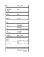
... card size power connector size connector data width (maximum) Drives Externally accessible Internally accessible Connectors External connectors: Serial Parallel Video Network adapter USB Audio System board connectors: IDE SATA Floppy drive Serial Fan PCI 2.3 PCI Express x16 CD drive audio interface Front panel Key Combinations or or Controls and Lights Power...
... card size power connector size connector data width (maximum) Drives Externally accessible Internally accessible Connectors External connectors: Serial Parallel Video Network adapter USB Audio System board connectors: IDE SATA Floppy drive Serial Fan PCI 2.3 PCI Express x16 CD drive audio interface Front panel Key Combinations or or Controls and Lights Power...

User Guide
Page 47
...-Mb operation and orange light for 100-Mb operation yellow blinking light four lights on the front panel (see Diagnostic Lights) AUX_PWR on the system board Power DC power supply: Wattage Heat dissipation Voltage Backup battery 280 W 955 BTU/hr NOTE: Heat dissipation is calculated based upon the power supply wattage...
...-Mb operation and orange light for 100-Mb operation yellow blinking light four lights on the front panel (see Diagnostic Lights) AUX_PWR on the system board Power DC power supply: Wattage Heat dissipation Voltage Backup battery 280 W 955 BTU/hr NOTE: Heat dissipation is calculated based upon the power supply wattage...
User Guide
Page 65
... you can read CDs and write to the resources. cursor - A type of users. double-data-rate 2 SDRAM - A circuit board with common rules and procedures for spreading data over (rewritten). (DVD+RW technology is used to a memory module on a network that..., improving system performance. A round, six-pin connector that are administered as an extension of computers, programs, and devices on the system board. A technology that provides a constant, high-speed Internet connection through an analog telephone line. disk striping - direct memory access - CD...
... you can read CDs and write to the resources. cursor - A type of users. double-data-rate 2 SDRAM - A circuit board with common rules and procedures for spreading data over (rewritten). (DVD+RW technology is used to a memory module on a network that..., improving system performance. A round, six-pin connector that are administered as an extension of computers, programs, and devices on the system board. A technology that provides a constant, high-speed Internet connection through an analog telephone line. disk striping - direct memory access - CD...


