
Service Manual
Page 3
Contents Chapter 1 System Overview 1-1 System Features 1-1 Physical Description 1-2 Indicator Panel 1-3 Power/Suspend Indicator 1-4 Diskette-Drive Access Indicator 1-4 Hard-Disk/CD-ROM Drive Access Indicator 1-4 PC Card Access Indicator 1-4 Low-Battery Indicator 1-4 Charging Indicator 1-4 Keyboard Indicators 1-5 Controlling Computer Power 1-5 Power States 1-5 Interrupt Assignments 1-6 Technical Specifications 1-7 Chapter 2 Initial Procedures 2-1 Initial User Contact 2-1 Visual Inspection 2-1 Observing...
Contents Chapter 1 System Overview 1-1 System Features 1-1 Physical Description 1-2 Indicator Panel 1-3 Power/Suspend Indicator 1-4 Diskette-Drive Access Indicator 1-4 Hard-Disk/CD-ROM Drive Access Indicator 1-4 PC Card Access Indicator 1-4 Low-Battery Indicator 1-4 Charging Indicator 1-4 Keyboard Indicators 1-5 Controlling Computer Power 1-5 Power States 1-5 Interrupt Assignments 1-6 Technical Specifications 1-7 Chapter 2 Initial Procedures 2-1 Initial User Contact 2-1 Visual Inspection 2-1 Observing...
Service Manual
Page 4
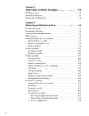
Chapter 3 Beep Codes and Error Messages 3-1 POST Beep Codes 3-1 System Error Messages 3-3 Running the Dell Diagnostics 3-8 Chapter 4 Removing and Replacing Parts 4-1 Recommended Tools 4-2 Precautionary Measures 4-2 Screw Identification and Tightening 4-4 ZIF Connectors 4-5 Field-... 4-25 Display-Assembly Interface Cable 4-26 Microphone/Switch Assembly 4-28 Bottom Case Assembly 4-29 Diskette/CD-ROM Drive Assembly 4-31 Deck Buoy 4-33 Superpart Assembly 4-34 Reserve Battery 4-36 System Board Assembly 4-38 Removing the System Board Assembly 4-39 Replacing the System Board Assembly...
Chapter 3 Beep Codes and Error Messages 3-1 POST Beep Codes 3-1 System Error Messages 3-3 Running the Dell Diagnostics 3-8 Chapter 4 Removing and Replacing Parts 4-1 Recommended Tools 4-2 Precautionary Measures 4-2 Screw Identification and Tightening 4-4 ZIF Connectors 4-5 Field-... 4-25 Display-Assembly Interface Cable 4-26 Microphone/Switch Assembly 4-28 Bottom Case Assembly 4-29 Diskette/CD-ROM Drive Assembly 4-31 Deck Buoy 4-33 Superpart Assembly 4-34 Reserve Battery 4-36 System Board Assembly 4-38 Removing the System Board Assembly 4-39 Replacing the System Board Assembly...

Service Manual
Page 5
... Recommended Tools A-1 Precautionary Measures A-1 Factory Repair Parts and Assemblies A-1 Exploded Views of Components and Assemblies A-12 Hard-Disk Drive A-15 CD-ROM Drive A-16 Diskette Drive A-16 Palmrest Assembly Components A-16 Trackball A-16 Trackball Interface Cable A-16 Trackball Button Board A-16 Palmrest ... Shield A-21 I/O Interface Cable A-22 I/O Board A-23 I/O Panel A-24 Bottom-Case Assembly Components A-25 Main Battery Insulator A-25 Power Button and Power-Button Mounting Bracket A-26 Spreader and Keel Plates A-27 Appendix B System Setup Options B-1 Accessing the...
... Recommended Tools A-1 Precautionary Measures A-1 Factory Repair Parts and Assemblies A-1 Exploded Views of Components and Assemblies A-12 Hard-Disk Drive A-15 CD-ROM Drive A-16 Diskette Drive A-16 Palmrest Assembly Components A-16 Trackball A-16 Trackball Interface Cable A-16 Trackball Button Board A-16 Palmrest ... Shield A-21 I/O Interface Cable A-22 I/O Board A-23 I/O Panel A-24 Bottom-Case Assembly Components A-25 Main Battery Insulator A-25 Power Button and Power-Button Mounting Bracket A-26 Spreader and Keel Plates A-27 Appendix B System Setup Options B-1 Accessing the...

Service Manual
Page 6
...10 Figure 4-10. Tilt-Support Foot Removal 4-16 Figure 4-14. Display Assembly Latch and Latch Spring Removal 4-21 Figure 4-17. Reserve Battery Removal 4-36 Figure 4-27. I /O-Panel Dust Cover Removal 4-42 Figure 4-31. Indicator Panel 1-3 Figure 4-1. Computer Orientation 4-1 Figure...Connector Dust Cover 4-43 Figure 4-32. Display Assembly Removal 4-18 Figure 4-15. Hinge Covers Removal 4-25 Figure 4-20. Diskette/CD-ROM Drive Assembly Removal 4-31 Figure 4-24. Screw Identification 4-4 Figure 4-4. Deck Buoy Removal 4-33 Figure 4-25. Superpart Assembly ...
...10 Figure 4-10. Tilt-Support Foot Removal 4-16 Figure 4-14. Display Assembly Latch and Latch Spring Removal 4-21 Figure 4-17. Reserve Battery Removal 4-36 Figure 4-27. I /O-Panel Dust Cover Removal 4-42 Figure 4-31. Indicator Panel 1-3 Figure 4-1. Computer Orientation 4-1 Figure...Connector Dust Cover 4-43 Figure 4-32. Display Assembly Removal 4-18 Figure 4-15. Hinge Covers Removal 4-25 Figure 4-20. Diskette/CD-ROM Drive Assembly Removal 4-31 Figure 4-24. Screw Identification 4-4 Figure 4-4. Deck Buoy Removal 4-33 Figure 4-25. Superpart Assembly ...

Service Manual
Page 10
Front View of the Notebook Computer 1-2 Dell Latitude XPi CD Service Manual Physical Description display assembly LCD panel keyboard trackball assembly display assembly latch indicator panel microphone tilt-support foot (2) infrared port diskette drive main battery assembly speaker bottom case assembly CD-ROM drive Figure 1-1.
Front View of the Notebook Computer 1-2 Dell Latitude XPi CD Service Manual Physical Description display assembly LCD panel keyboard trackball assembly display assembly latch indicator panel microphone tilt-support foot (2) infrared port diskette drive main battery assembly speaker bottom case assembly CD-ROM drive Figure 1-1.
Service Manual
Page 11
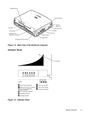
Indicator Panel Num Lock indicator Caps Lock indicator Scroll Lock indicator System Overview 1-3 Back View of the Notebook Computer Indicator Panel LCD panel Legend power/suspend indicator diskette-drive access indicator hard-disk/CD-ROM drive access indicator PC Card access indicator low-battery indicator charging indicator Figure 1-3. indicator panel hard-disk drive I/O panel infrared port Advanced Port Replicator connector DC power input connector security cable slot audio jacks (3) speaker PC Card slot power switch tilt-support foot Figure 1-2.
Indicator Panel Num Lock indicator Caps Lock indicator Scroll Lock indicator System Overview 1-3 Back View of the Notebook Computer Indicator Panel LCD panel Legend power/suspend indicator diskette-drive access indicator hard-disk/CD-ROM drive access indicator PC Card access indicator low-battery indicator charging indicator Figure 1-3. indicator panel hard-disk drive I/O panel infrared port Advanced Port Replicator connector DC power input connector security cable slot audio jacks (3) speaker PC Card slot power switch tilt-support foot Figure 1-2.

Service Manual
Page 12
... when data is fully charged. 1-4 Dell Latitude XPi CD Service Manual PC Card Access Indicator The PC Card access indicator is used in conjunction with the speaker to indicate either of the following low-battery conditions: • The first low-battery warning occurs when the main battery's charge has been depleted to 8 ...the indicator panel when the display is open, and the other is visible through an aperture on when the main battery begins charging and blinks to show the battery is being transferred to or from an installed PC Card (also known as a PCMCIA card). The indicator lights...
... when data is fully charged. 1-4 Dell Latitude XPi CD Service Manual PC Card Access Indicator The PC Card access indicator is used in conjunction with the speaker to indicate either of the following low-battery conditions: • The first low-battery warning occurs when the main battery's charge has been depleted to 8 ...the indicator panel when the display is open, and the other is visible through an aperture on when the main battery begins charging and blinks to show the battery is being transferred to or from an installed PC Card (also known as a PCMCIA card). The indicator lights...
Service Manual
Page 18
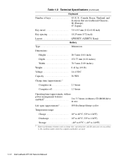
...); 87 (Japan) Key travel 3.0 ± 0.5 mm (0.12 ± 0.02 inch) Key spacing 18.25 mm (0.72 inch) Layout QWERTY, AZERTY, Kanji Battery Type lithium ion Dimensions: Height 20.5 mm (0.81 inch) Depth 152.75 mm (6.01 inches) Width 78.5 mm (3.09 inches) Weight 0.41 kg (0.9 lb)...to 40°C (50° to 104°F) Storage 40° to 65°C (-40° to 149°F) 2 Battery performance features such as charge time, operating time, and life span can vary according to the conditions under which the computer and battery are used. 1-10 Dell Latitude XPi CD Service Manual
...); 87 (Japan) Key travel 3.0 ± 0.5 mm (0.12 ± 0.02 inch) Key spacing 18.25 mm (0.72 inch) Layout QWERTY, AZERTY, Kanji Battery Type lithium ion Dimensions: Height 20.5 mm (0.81 inch) Depth 152.75 mm (6.01 inches) Width 78.5 mm (3.09 inches) Weight 0.41 kg (0.9 lb)...to 40°C (50° to 104°F) Storage 40° to 65°C (-40° to 149°F) 2 Battery performance features such as charge time, operating time, and life span can vary according to the conditions under which the computer and battery are used. 1-10 Dell Latitude XPi CD Service Manual
Service Manual
Page 19
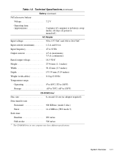
System Overview 1-11 Technical Specifications (Continued) Battery (Continued) NiCad reserve battery: Voltage 7.2 V Operating time (approximate 2 minutes (if computer is in battery swap mode); 40 days (if power is turned off) AC Adapter Input voltage 90 to 135 VAC and 164 to 264 VAC Input current (...) Temperature range: Operating 0° to 40°C (32° to 104°F) Storage 40° to 70°C (-40° to 158°F) CD-ROM Drive3 Disc size 8 cm and 12 cm (no adapter required) Data transfer rate: Sustained 900 KB/sec (mode 2 disc) Burst 14.4 MB/sec (PIO...
System Overview 1-11 Technical Specifications (Continued) Battery (Continued) NiCad reserve battery: Voltage 7.2 V Operating time (approximate 2 minutes (if computer is in battery swap mode); 40 days (if power is turned off) AC Adapter Input voltage 90 to 135 VAC and 164 to 264 VAC Input current (...) Temperature range: Operating 0° to 40°C (32° to 104°F) Storage 40° to 70°C (-40° to 158°F) CD-ROM Drive3 Disc size 8 cm and 12 cm (no adapter required) Data transfer rate: Sustained 900 KB/sec (mode 2 disc) Burst 14.4 MB/sec (PIO...

Service Manual
Page 20
Technical Specifications (Continued) CD-ROM Drive3 (Continued) Access time: Random 250 m/sec Full-stroke 550 m/sec Memory buffer 128 KB Physical (Computer) Height 63.0 mm (2.48 inches) Width 280.9 mm (11.06 inches) Depth 233.5 mm (9.19 inches) Weight (with battery and hard-disk drive 3.29 kg (7.26 lb) ... 0.51 GRMS, using a random-vibration spectrum that simulates truck shipment Storage 1.1 GRMS, using a random-vibration spectrum that simulates air/truck shipment 3 The CD-ROM drive in your computer may have different specifications. 1-12 Dell Latitude XPi CD Service Manual Table 1-2.
Technical Specifications (Continued) CD-ROM Drive3 (Continued) Access time: Random 250 m/sec Full-stroke 550 m/sec Memory buffer 128 KB Physical (Computer) Height 63.0 mm (2.48 inches) Width 280.9 mm (11.06 inches) Depth 233.5 mm (9.19 inches) Weight (with battery and hard-disk drive 3.29 kg (7.26 lb) ... 0.51 GRMS, using a random-vibration spectrum that simulates truck shipment Storage 1.1 GRMS, using a random-vibration spectrum that simulates air/truck shipment 3 The CD-ROM drive in your computer may have different specifications. 1-12 Dell Latitude XPi CD Service Manual Table 1-2.

Service Manual
Page 24
... on or blinking - If the computer is too warm; A defective battery is detected or the computer is not allowed to cool, the battery stops charging before it reaches full capacity. 2-2 Dell Latitude XPi CD Service Manual The computer is already turned off the computer. • Low-battery and charging indicators are free of any attached peripherals. 2. Look...
... on or blinking - If the computer is too warm; A defective battery is detected or the computer is not allowed to cool, the battery stops charging before it reaches full capacity. 2-2 Dell Latitude XPi CD Service Manual The computer is already turned off the computer. • Low-battery and charging indicators are free of any attached peripherals. 2. Look...

Service Manual
Page 30
... port failure Parallel port test failure Math coprocessor failure Memory module improperly seated or system memory controller faulty (system board faulty) System board faulty Reserve battery faulty or system board faulty System board faulty System board faulty System board faulty 3-2 Dell Latitude XPi CD Service Manual Table 3-1.
... port failure Parallel port test failure Math coprocessor failure Memory module improperly seated or system memory controller faulty (system board faulty) System board faulty Reserve battery faulty or system board faulty System board faulty System board faulty System board faulty 3-2 Dell Latitude XPi CD Service Manual Table 3-1.
Service Manual
Page 33
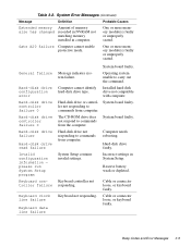
...Keyboard data line failure Message indicates system failure. Hard-disk drive or controller not responding to commands from the computer. The CD-ROM drive does not respond to carry out the command. Operating system unable to commands from computer. Beep Codes and ...Cable or connector loose, or keyboard faulty. One or more memory module(s) faulty or improperly seated. Hard-disk drive faulty. Reserve battery weak or depleted. Keyboard controller not responding. Computer cannot identify hard-disk drive type. Cable or connector loose, or keyboard faulty. ...
...Keyboard data line failure Message indicates system failure. Hard-disk drive or controller not responding to commands from the computer. The CD-ROM drive does not respond to carry out the command. Operating system unable to commands from computer. Beep Codes and ...Cable or connector loose, or keyboard faulty. One or more memory module(s) faulty or improperly seated. Hard-disk drive faulty. Reserve battery weak or depleted. Keyboard controller not responding. Computer cannot identify hard-disk drive type. Cable or connector loose, or keyboard faulty. ...

Service Manual
Page 36
...day clock stopped Time-of -day System clock stopped. Timer chip Timer circuit on diskette or hard-disk drive. Main battery has lost its charge. System board faulty. Tests the keyboard subsystem • Mouse - Tests the IDE hard-disk drive subsystem •... (Non-SCSI) - Warning! Tests the main memory • System Set - Tests the video subsystem • Keyboard - Tests the CD-ROM drive subsystem 3-8 Dell Latitude XPi CD Service Manual Shutdown failure Microprocessor unable to find specific track on system counter 2 failed board malfunctioning. Time or date stored in the Reference ...
...day clock stopped Time-of -day System clock stopped. Timer chip Timer circuit on diskette or hard-disk drive. Main battery has lost its charge. System board faulty. Tests the keyboard subsystem • Mouse - Tests the IDE hard-disk drive subsystem •... (Non-SCSI) - Warning! Tests the main memory • System Set - Tests the video subsystem • Keyboard - Tests the CD-ROM drive subsystem 3-8 Dell Latitude XPi CD Service Manual Shutdown failure Microprocessor unable to find specific track on system counter 2 failed board malfunctioning. Time or date stored in the Reference ...
Service Manual
Page 40
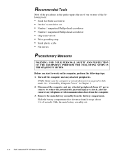
... 3. See "Controlling Computer Power" in this guide require the use of one or more of the following steps: 1. Remove the main battery assembly from AC power sources to work on the computer, perform the following tools: • Small flat-blade screwdriver • Jeweler's screwdriver...door downward until it stops (about 3/16 of an inch). Also disconnect any attached peripherals from the battery compartment. Slide the main battery assembly out. 4-2 Dell Latitude XPi CD Service Manual NOTE: Make sure the computer is turned off the computer and any attached peripherals. Before you...
... 3. See "Controlling Computer Power" in this guide require the use of one or more of the following steps: 1. Remove the main battery assembly from AC power sources to work on the computer, perform the following tools: • Small flat-blade screwdriver • Jeweler's screwdriver...door downward until it stops (about 3/16 of an inch). Also disconnect any attached peripherals from the battery compartment. Slide the main battery assembly out. 4-2 Dell Latitude XPi CD Service Manual NOTE: Make sure the computer is turned off the computer and any attached peripherals. Before you...
Service Manual
Page 44
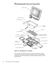
... main battery memory compartment cover CD-ROM/diskette drive assembly Figure 4-5. Exploded View-Computer The computer is divided into three major assemblies: the palmrest assembly (which contains the keyboard and the trackball), the display assembly (which contains the LCD), and the bottom case assembly (which contains many of the removable parts). 4-6 Dell Latitude XPi CD Service...
... main battery memory compartment cover CD-ROM/diskette drive assembly Figure 4-5. Exploded View-Computer The computer is divided into three major assemblies: the palmrest assembly (which contains the keyboard and the trackball), the display assembly (which contains the LCD), and the bottom case assembly (which contains many of the removable parts). 4-6 Dell Latitude XPi CD Service...

Service Manual
Page 72
... The superpart assembly includes two speakers, two fans, the reserve battery, a printed circuit board for those parts, and an infrared printed circuit board. To remove the superpart assembly, follow these steps: 1. Remove the deck-buoy. 4-34 Dell Latitude XPi CD Service Manual Remove the diskette-drive/CD-ROM assembly. 4. Remove the palmrest assembly. 2. Remove the display...
... The superpart assembly includes two speakers, two fans, the reserve battery, a printed circuit board for those parts, and an infrared printed circuit board. To remove the superpart assembly, follow these steps: 1. Remove the deck-buoy. 4-34 Dell Latitude XPi CD Service Manual Remove the diskette-drive/CD-ROM assembly. 4. Remove the palmrest assembly. 2. Remove the display...
Service Manual
Page 74
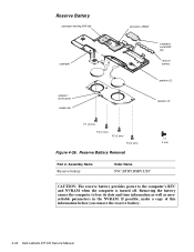
...F2 (3 mm) F3 (3 mm) F4 (3 mm) 3 mm Figure 4-26. If possible, make a copy of this information before you remove the reserve battery. 4-36 Dell Latitude XPi CD Service Manual Removing the battery causes the computer to the computer's RTC and NVRAM when the computer is turned off. Reserve... Battery Removal Part or Assembly Name Reserve battery Order Name SVC,BTRY,RSRV,LXP CAUTION: The reserve battery provides power to lose its date ...
...F2 (3 mm) F3 (3 mm) F4 (3 mm) 3 mm Figure 4-26. If possible, make a copy of this information before you remove the reserve battery. 4-36 Dell Latitude XPi CD Service Manual Removing the battery causes the computer to the computer's RTC and NVRAM when the computer is turned off. Reserve... Battery Removal Part or Assembly Name Reserve battery Order Name SVC,BTRY,RSRV,LXP CAUTION: The reserve battery provides power to lose its date ...

Service Manual
Page 76
... the computer. Do not neglect to transfer the service tag number to the replacement system board assembly. 4-38 Dell Latitude XPi CD Service Manual System Board Assembly PC Card ejectors SB1 (5 mm) I/O docking EMI clip system board assembly SB2 (5 mm) I/O serial EMI clip main battery connector battery compartment 5 mm molded tabs (3) bottom case assembly Figure 4-27.
... the computer. Do not neglect to transfer the service tag number to the replacement system board assembly. 4-38 Dell Latitude XPi CD Service Manual System Board Assembly PC Card ejectors SB1 (5 mm) I/O docking EMI clip system board assembly SB2 (5 mm) I/O serial EMI clip main battery connector battery compartment 5 mm molded tabs (3) bottom case assembly Figure 4-27.

Service Manual
Page 77
Removing the System Board Assembly To remove the system board assembly, follow these steps: 1. Remove the diskette/CD-ROM assembly. 4. Remove the deck buoy plate. (Reinstall this part on the new system board.) CAUTION: To ensure maximum cooling for the microprocessor, do not ... the system board from the I/O docking EMI and serial EMI clips. 7. CAUTION: When removing the system board assembly, be careful not to damage the main battery connector and EMI shield on the deck buoy plate. Verify that the PC Card ejectors are located alongside the hard-disk drive compartment, inside the...
Removing the System Board Assembly To remove the system board assembly, follow these steps: 1. Remove the diskette/CD-ROM assembly. 4. Remove the deck buoy plate. (Reinstall this part on the new system board.) CAUTION: To ensure maximum cooling for the microprocessor, do not ... the system board from the I/O docking EMI and serial EMI clips. 7. CAUTION: When removing the system board assembly, be careful not to damage the main battery connector and EMI shield on the deck buoy plate. Verify that the PC Card ejectors are located alongside the hard-disk drive compartment, inside the...

