

Service Manual
Page 2
... NOTICE indicates either the entities claiming the marks and names or their products. Reproduction in this text: Dell, the DELL logo, and Latitude are registered trademarks of Microsoft Corporation; Other trademarks and trade names may be used in any manner whatsoever... as is subject to all Dell systems. © 2008 Dell Inc. disclaims any proprietary interest in this document is , without notice. and is provided for property damage, personal injury, or death. Dell Inc. Some of Dell Inc.; DellTM XFR D630 Fully Rugged Notebook Service Manual Notes, Notices, and Cautions ...
... NOTICE indicates either the entities claiming the marks and names or their products. Reproduction in this text: Dell, the DELL logo, and Latitude are registered trademarks of Microsoft Corporation; Other trademarks and trade names may be used in any manner whatsoever... as is subject to all Dell systems. © 2008 Dell Inc. disclaims any proprietary interest in this document is , without notice. and is provided for property damage, personal injury, or death. Dell Inc. Some of Dell Inc.; DellTM XFR D630 Fully Rugged Notebook Service Manual Notes, Notices, and Cautions ...

Service Manual
Page 3
DellTM XFR D630 Fully Rugged Notebook Service Manual Table of Contents 1 BEFORE YOU BEGIN ...6 1.1 RECOMMENDED TOOLS ...6 1.2 TURNING OFF YOUR COMPUTER 6 1.3 BEFORE WORKING INSIDE YOUR COMPUTER 6 1.4 SCREW CHART ...8 2 XBAY DEVICES ...13 3 HARD DRIVE...14 4 ...
DellTM XFR D630 Fully Rugged Notebook Service Manual Table of Contents 1 BEFORE YOU BEGIN ...6 1.1 RECOMMENDED TOOLS ...6 1.2 TURNING OFF YOUR COMPUTER 6 1.3 BEFORE WORKING INSIDE YOUR COMPUTER 6 1.4 SCREW CHART ...8 2 XBAY DEVICES ...13 3 HARD DRIVE...14 4 ...

Service Manual
Page 4
DellTM XFR D630 Fully Rugged Notebook Service Manual 10.10 INSTALLING THE DISPLAY LATCH 68 11 INTERNAL CARD WITH BLUETOOTH® WIRELESS TECHNOLOGY 68 11.1 REMOVING THE BLUETOOTH® WIRELESS CARD 68 11.2 ...
DellTM XFR D630 Fully Rugged Notebook Service Manual 10.10 INSTALLING THE DISPLAY LATCH 68 11 INTERNAL CARD WITH BLUETOOTH® WIRELESS TECHNOLOGY 68 11.1 REMOVING THE BLUETOOTH® WIRELESS CARD 68 11.2 ...

Service Manual
Page 5
DellTM XFR D630 Fully Rugged Notebook Service Manual 24 RF PASSTHRU BOARD 102 24.1 REMOVING THE RF PASSTHRU BOARD 102 24.2 INSTALLING THE RF PASSTHRU BOARD 103 25 BOTTOM CHASSIS 104 25.1 25.2 25.3 25.4 REMOVING THE BOTTOM CHASSIS 104 INSTALLING THE BOTTOM CHASSIS 105 REMOVING THE MODEM CABLE 105 INSTALLING THE MODEM CABLE 105 Page 5 of 106 Revision A01
DellTM XFR D630 Fully Rugged Notebook Service Manual 24 RF PASSTHRU BOARD 102 24.1 REMOVING THE RF PASSTHRU BOARD 102 24.2 INSTALLING THE RF PASSTHRU BOARD 103 25 BOTTOM CHASSIS 104 25.1 25.2 25.3 25.4 REMOVING THE BOTTOM CHASSIS 104 INSTALLING THE BOTTOM CHASSIS 105 REMOVING THE MODEM CABLE 105 INSTALLING THE MODEM CABLE 105 Page 5 of 106 Revision A01

Service Manual
Page 6
...components in this section, follow the safety instructions in the XFR D630 Product Information Guide and in the XFR D630 User's Guide. • A component can be replaced by your warranty. Ensure that is not authorized by Dell is not covered by performing the removal procedure in reverse... 94H Assembly) 1.2 Turning Off Your Computer NOTICE: To avoid losing data, save and close any open programs b. DellTM XFR D630 Fully Rugged Notebook Service Manual 1 Before You Begin This chapter provides procedures for 4 seconds. 1.3 Before Working Inside Your Computer Use the following safety ...
...components in this section, follow the safety instructions in the XFR D630 Product Information Guide and in the XFR D630 User's Guide. • A component can be replaced by your warranty. Ensure that is not authorized by Dell is not covered by performing the removal procedure in reverse... 94H Assembly) 1.2 Turning Off Your Computer NOTICE: To avoid losing data, save and close any open programs b. DellTM XFR D630 Fully Rugged Notebook Service Manual 1 Before You Begin This chapter provides procedures for 4 seconds. 1.3 Before Working Inside Your Computer Use the following safety ...

Service Manual
Page 7
... you are not installed, proceed to assist in on the left, front side of cable, press in lifting the battery from their electrical outlets. 5. DellTM XFR D630 Fully Rugged Notebook Service Manual itself.
... you are not installed, proceed to assist in on the left, front side of cable, press in lifting the battery from their electrical outlets. 5. DellTM XFR D630 Fully Rugged Notebook Service Manual itself.

Service Manual
Page 8
DellTM XFR D630 Fully Rugged Notebook Service Manual PC Card Slot c. Then close the protective door. 1.4 Screw Chart SCREW IMAGE PART NUMBER DESCRIPTION 18114 SHOULDER SCREW M2.5 18815 XFR LCD ASSY TOUCH SCREEN Qty/Assy Total Qty 6 6 18279 CHEESE HEAD SCREW M1.2 X 3 18806 18808 18812 AV DOOR ASSY VGA DOOR ASSY DVD DOOR ASSY 1 3 1 1 18353 SHOULDER SCREW-HEAT SPREADER 3 18035 HEAT SINK ASSY 3 18415 PAN HEAD SCREW M2.5 X 8 -BLACK 19 Page 8 of 106 Revision A01 d. Remove the PC Card or Express Card.
DellTM XFR D630 Fully Rugged Notebook Service Manual PC Card Slot c. Then close the protective door. 1.4 Screw Chart SCREW IMAGE PART NUMBER DESCRIPTION 18114 SHOULDER SCREW M2.5 18815 XFR LCD ASSY TOUCH SCREEN Qty/Assy Total Qty 6 6 18279 CHEESE HEAD SCREW M1.2 X 3 18806 18808 18812 AV DOOR ASSY VGA DOOR ASSY DVD DOOR ASSY 1 3 1 1 18353 SHOULDER SCREW-HEAT SPREADER 3 18035 HEAT SINK ASSY 3 18415 PAN HEAD SCREW M2.5 X 8 -BLACK 19 Page 8 of 106 Revision A01 d. Remove the PC Card or Express Card.

Service Manual
Page 9
DellTM XFR D630 Fully Rugged Notebook Service Manual 18815 XFR LCD ASSY TOUCH SCREEN 4 18802 PALMREST ASSY 11 18043 ASSY HANDLE WITH HOLDER 2 18619 LCD LATCH ASSY 2 18416 18044 18824 SCR,M3X14,PHH,MSCR,ZPS,XFR ASSY HANDLE SHOULDER STRAP ASSY 8 6 2 18417 PAN HEAD SCREW M2 X 12 -BLACK 7 18815 XFR LCD ASSY TOUCH SCREEN 7 18419 PAN HEAD...
DellTM XFR D630 Fully Rugged Notebook Service Manual 18815 XFR LCD ASSY TOUCH SCREEN 4 18802 PALMREST ASSY 11 18043 ASSY HANDLE WITH HOLDER 2 18619 LCD LATCH ASSY 2 18416 18044 18824 SCR,M3X14,PHH,MSCR,ZPS,XFR ASSY HANDLE SHOULDER STRAP ASSY 8 6 2 18417 PAN HEAD SCREW M2 X 12 -BLACK 7 18815 XFR LCD ASSY TOUCH SCREEN 7 18419 PAN HEAD...

Service Manual
Page 10
DellTM XFR D630 Fully Rugged Notebook Service Manual 18806 18810 18804 18807 18811 18623 18424 18043 18425 18043 18044 18426 18806 18808 18812 18802 18618 AV DOOR ASSY HDD DOOR ASSY FAN COVER BATTERY DOOR ASSY DOCKING DOOR ASSY KEYBOARD ASSY CSK SCREW M3 X 10 -BLACK ASSY HANDLE WITH HOLDER CSK SCREW M2 X 10 -BLACK ASSY HANDLE WITH HOLDER ASSY HANDLE CSK SCREW M2 X 3 -BLACK AV DOOR ASSY VGA DOOR ASSY DVD DOOR ASSY PALMREST ASSY AV DOOR COVER ASSY 4 2 4 2 6 4 4 4 4 2 2 2 2 10 2 2 2 18427 CSK SCREW M2.5 X 6 -BLACK 3 Page 10 of 106 Revision A01
DellTM XFR D630 Fully Rugged Notebook Service Manual 18806 18810 18804 18807 18811 18623 18424 18043 18425 18043 18044 18426 18806 18808 18812 18802 18618 AV DOOR ASSY HDD DOOR ASSY FAN COVER BATTERY DOOR ASSY DOCKING DOOR ASSY KEYBOARD ASSY CSK SCREW M3 X 10 -BLACK ASSY HANDLE WITH HOLDER CSK SCREW M2 X 10 -BLACK ASSY HANDLE WITH HOLDER ASSY HANDLE CSK SCREW M2 X 3 -BLACK AV DOOR ASSY VGA DOOR ASSY DVD DOOR ASSY PALMREST ASSY AV DOOR COVER ASSY 4 2 4 2 6 4 4 4 4 2 2 2 2 10 2 2 2 18427 CSK SCREW M2.5 X 6 -BLACK 3 Page 10 of 106 Revision A01

Service Manual
Page 11
DellTM XFR D630 Fully Rugged Notebook Service Manual 18808 18812 18428 18815 18808 18802 18813 18814 18429 18810 18807 18630 18809 18631 18632 18628 18444 18815 18803 VGA DOOR ASSY DVD DOOR ASSY CSK SCREW M2 X 8 -BLACK XFR LCD ASSY TOUCH SCREEN VGA DOOR ASSY PALMREST ASSY RJ DOOR ASSY USB PLASTIC DOOR ASSY CSK SCREW M2 X 6 -BLACK HDD DOOR ASSY BATTERY DOOR ASSY USB SIDE DOOR ASSY DIMMS DOOR ASSY POWER DOOR ASSY PCMCIA DOOR ASSY RUBBER KEYBOARD ASSY SCR,M2.5X5,PHH,TF,BCS XFR LCD ASSY TOUCH SCREEN MOTHERBOARD TO CHASSIS 1 2 2 2 10 2 2 2 2 2 2 30 4 2 3 15 10 6 4 Page 11 of 106 Revision A01
DellTM XFR D630 Fully Rugged Notebook Service Manual 18808 18812 18428 18815 18808 18802 18813 18814 18429 18810 18807 18630 18809 18631 18632 18628 18444 18815 18803 VGA DOOR ASSY DVD DOOR ASSY CSK SCREW M2 X 8 -BLACK XFR LCD ASSY TOUCH SCREEN VGA DOOR ASSY PALMREST ASSY RJ DOOR ASSY USB PLASTIC DOOR ASSY CSK SCREW M2 X 6 -BLACK HDD DOOR ASSY BATTERY DOOR ASSY USB SIDE DOOR ASSY DIMMS DOOR ASSY POWER DOOR ASSY PCMCIA DOOR ASSY RUBBER KEYBOARD ASSY SCR,M2.5X5,PHH,TF,BCS XFR LCD ASSY TOUCH SCREEN MOTHERBOARD TO CHASSIS 1 2 2 2 10 2 2 2 2 2 2 30 4 2 3 15 10 6 4 Page 11 of 106 Revision A01

Service Manual
Page 12
DellTM XFR D630 Fully Rugged Notebook Service Manual 18451 18802 18477 18802 18043 18803 18819 18517 18044 18535 18623 18816 18539 18629 18550 18824 PAN HEAD SCREW M2 X 8-BLACK PALMREST ASSY PANHEAD SCREW M2X4 PALMREST ASSY ASSY HANDLE WITH HOLDER RF PASS THROUGH LCD TOP COVER ASSY SCR,M3X6,PHH,MSCR,ZPS,XFR ASSY HANDLE CSK CAPTIVE SCREW M2 X 6 KEYBOARD ASSY HINGE COVER ASSY PAN HEAD SCREW M3 X 14 -BLACK STYLUS KIT ASSY PAN HEAD SCREW M3 X 22 -BLACK SHOULDER STRAP ASSY 1 1 1 9 4 2 2 2 2 19 15 4 1 1 2 2 18590 SCREW,KYBD BLK, PAN HEAD M2X3 19 Page 12 of 106 Revision A01
DellTM XFR D630 Fully Rugged Notebook Service Manual 18451 18802 18477 18802 18043 18803 18819 18517 18044 18535 18623 18816 18539 18629 18550 18824 PAN HEAD SCREW M2 X 8-BLACK PALMREST ASSY PANHEAD SCREW M2X4 PALMREST ASSY ASSY HANDLE WITH HOLDER RF PASS THROUGH LCD TOP COVER ASSY SCR,M3X6,PHH,MSCR,ZPS,XFR ASSY HANDLE CSK CAPTIVE SCREW M2 X 6 KEYBOARD ASSY HINGE COVER ASSY PAN HEAD SCREW M3 X 14 -BLACK STYLUS KIT ASSY PAN HEAD SCREW M3 X 22 -BLACK SHOULDER STRAP ASSY 1 1 1 9 4 2 2 2 2 19 15 4 1 1 2 2 18590 SCREW,KYBD BLK, PAN HEAD M2X3 19 Page 12 of 106 Revision A01

Service Manual
Page 13
... to a docking device (docked). 1. If the computer is running and connected to eject, and click Stop. 3. Page 13 of the computer. 2. DellTM XFR D630 Fully Rugged Notebook Service Manual 18815 XFR LCD ASSY TOUCH SCREEN 8 18802 PALMREST ASSY 2 18803 CARD CAGE ON BASE CHASSIS 4 18623 KEYBOARD ASSY 3 18823 MOTHERBOARD ASSY 2 18591 18802 PAN HEAD...
... to a docking device (docked). 1. If the computer is running and connected to eject, and click Stop. 3. Page 13 of the computer. 2. DellTM XFR D630 Fully Rugged Notebook Service Manual 18815 XFR LCD ASSY TOUCH SCREEN 8 18802 PALMREST ASSY 2 18803 CARD CAGE ON BASE CHASSIS 4 18623 KEYBOARD ASSY 3 18823 MOTHERBOARD ASSY 2 18591 18802 PAN HEAD...
Service Manual
Page 14
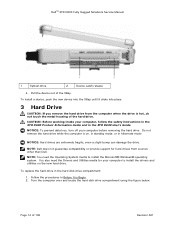
...the computer when the drive is on the new hard drive. Follow the procedures in the hard disk drive compartment: 1. DellTM XFR D630 Fully Rugged Notebook Service Manual 1 Optical drive 2 Device Latch release 4. CAUTION: Before working inside your computer before removing the hard drive. Turn the computer...Do not remove the hard drive while the computer is hot, do not touch the metal housing of 106 Revision A01 NOTE: Dell does not guarantee compatibility or provide support for your computer to install the Microsoft® Windows® operating system. To replace the...
...the computer when the drive is on the new hard drive. Follow the procedures in the hard disk drive compartment: 1. DellTM XFR D630 Fully Rugged Notebook Service Manual 1 Optical drive 2 Device Latch release 4. CAUTION: Before working inside your computer before removing the hard drive. Turn the computer...Do not remove the hard drive while the computer is hot, do not touch the metal housing of 106 Revision A01 NOTE: Dell does not guarantee compatibility or provide support for your computer to install the Microsoft® Windows® operating system. To replace the...
Service Manual
Page 15
Page 15 of 106 Revision A01 DellTM XFR D630 Fully Rugged Notebook Service Manual 3. Lift each latch, and turn each a quarter-turn latches are not installed, proceed to release the latching mechanism. If the 2 security screws are installed, remove the 2 screws on the latches on the hard disk drive compartment using a #1 Philips screw driver. If the 2 optional screws that secure the quarter-turn , towards the 'unlock' icon, to step 4. 4.
Page 15 of 106 Revision A01 DellTM XFR D630 Fully Rugged Notebook Service Manual 3. Lift each latch, and turn each a quarter-turn latches are not installed, proceed to release the latching mechanism. If the 2 security screws are installed, remove the 2 screws on the latches on the hard disk drive compartment using a #1 Philips screw driver. If the 2 optional screws that secure the quarter-turn , towards the 'unlock' icon, to step 4. 4.

Service Manual
Page 16
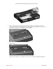
... tab to assist in protective antistatic packaging. 8. NOTICE: Use firm and even pressure to disconnect the hard disk drive from the compartment. DellTM XFR D630 Fully Rugged Notebook Service Manual 5. NOTICE: When the hard drive is not in the computer, store it back to slide the drive into place. Remove the new drive...
... tab to assist in protective antistatic packaging. 8. NOTICE: Use firm and even pressure to disconnect the hard disk drive from the compartment. DellTM XFR D630 Fully Rugged Notebook Service Manual 5. NOTICE: When the hard drive is not in the computer, store it back to slide the drive into place. Remove the new drive...
Service Manual
Page 17
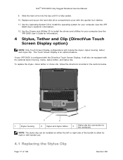
DellTM XFR D630 Fully Rugged Notebook Service Manual 9. The Touch Screen Display is fully seated. 10. If your computer (see the XFR D630 User's Guide for right or left or right side of 106 Revision A01 Use the Operating System CD to install the operating system for your computer (see the XFR D630 User's... either the left -handed use. 4.1 Replacing the Stylus Clip Page 17 of the handle to install the drivers and utilities for your XFR D630 is configured with the DirectVue Touch Screen Display, it is an optional feature. To replace the stylus, stylus tether or stylus clip, ...
DellTM XFR D630 Fully Rugged Notebook Service Manual 9. The Touch Screen Display is fully seated. 10. If your computer (see the XFR D630 User's Guide for right or left or right side of 106 Revision A01 Use the Operating System CD to install the operating system for your computer (see the XFR D630 User's... either the left -handed use. 4.1 Replacing the Stylus Clip Page 17 of the handle to install the drivers and utilities for your XFR D630 is configured with the DirectVue Touch Screen Display, it is an optional feature. To replace the stylus, stylus tether or stylus clip, ...
Service Manual
Page 18
... allow for right or left or right side of the handle cover. Slide the old stylus clip from beneath the loosened screw. 3. DellTM XFR D630 Fully Rugged Notebook Service Manual The stylus clip is installed on the handle assembly's end screw on the left -handed use. 2. If the clip is installed the opposite...
... allow for right or left or right side of the handle cover. Slide the old stylus clip from beneath the loosened screw. 3. DellTM XFR D630 Fully Rugged Notebook Service Manual The stylus clip is installed on the handle assembly's end screw on the left -handed use. 2. If the clip is installed the opposite...

Service Manual
Page 19
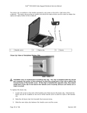
.... 2. c. b. This section provides instructions for right or left or right side of the tether through the loop until tight. 5 Handle The XFR D630 is now attached to allow for removing and installing the handle if replacement is free from the tether. 3. At the stylus, loosen the looped ...end of the tether. Place the free end of the handle to the tether. 4. DellTM XFR D630 Fully Rugged Notebook Service Manual 4. b. Page 19 of the handle to the other, remember to the stylus clip: a. NOTE: If you relocate the stylus from one...
.... 2. c. b. This section provides instructions for right or left or right side of the tether through the loop until tight. 5 Handle The XFR D630 is now attached to allow for removing and installing the handle if replacement is free from the tether. 3. At the stylus, loosen the looped ...end of the tether. Place the free end of the handle to the tether. 4. DellTM XFR D630 Fully Rugged Notebook Service Manual 4. b. Page 19 of the handle to the other, remember to the stylus clip: a. NOTE: If you relocate the stylus from one...

Service Manual
Page 20
...(3 on each side) on the top of the handle assembly that secure the main handle assembly. 5.2 Installing the Handle 1. Page 20 of the XFR D630 as shown in the front plate of 106 Revision A01 Install the 6 screws (3 on each handle cover) that secure the handle to the handle ...brackets. Align the main handle assembly with the mounting holes in the figure above . 2. DellTM XFR D630 Fully Rugged Notebook Service Manual 1 Main handle assembly 2 Handle cover (2) 5.1 Removing the Handle 1. Secure the main handle assembly to the...
...(3 on each side) on the top of the handle assembly that secure the main handle assembly. 5.2 Installing the Handle 1. Page 20 of the XFR D630 as shown in the front plate of 106 Revision A01 Install the 6 screws (3 on each handle cover) that secure the handle to the handle ...brackets. Align the main handle assembly with the mounting holes in the figure above . 2. DellTM XFR D630 Fully Rugged Notebook Service Manual 1 Main handle assembly 2 Handle cover (2) 5.1 Removing the Handle 1. Secure the main handle assembly to the...

Service Manual
Page 21
... secure the Comms Door. 2. Remove the Comms Door from the notebook. If your XFR D630 is located on each side). 6 Port Covers The XFR D630 utilizes port covers to Replacing the 97H Stylus Clip for instructions regarding installing the stylus clip... the handle assembly. 6. Align each of the handle covers over the main handle assembly and to the XFR D630 with the optional Touch Screen, please refer to secure and protect the connectors and devices of 106 Revision A01... the RJ-45 and RJ-11 connectors. 6.1.1 Removing the Comms Door 1. DellTM XFR D630 Fully Rugged Notebook Service Manual 4.
... secure the Comms Door. 2. Remove the Comms Door from the notebook. If your XFR D630 is located on each side). 6 Port Covers The XFR D630 utilizes port covers to Replacing the 97H Stylus Clip for instructions regarding installing the stylus clip... the handle assembly. 6. Align each of the handle covers over the main handle assembly and to the XFR D630 with the optional Touch Screen, please refer to secure and protect the connectors and devices of 106 Revision A01... the RJ-45 and RJ-11 connectors. 6.1.1 Removing the Comms Door 1. DellTM XFR D630 Fully Rugged Notebook Service Manual 4.


