User Manual
Page 2
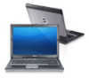
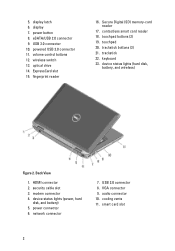
... slot 15. touchpad 20. powered USB 3.0 connector 11. device status lights (power, hard disk, and battery) 5. USB 3.0 connector 10. optical drive 14. network connector 7. display 7. keyboard 23. Back View 1. security cable slot 3. volume control buttons 12. display latch 6. touchpad buttons (2) 19. device status lights (hard disk, battery, and wireless) Figure 2. power...
... slot 15. touchpad 20. powered USB 3.0 connector 11. device status lights (power, hard disk, and battery) 5. USB 3.0 connector 10. optical drive 14. network connector 7. display 7. keyboard 23. Back View 1. security cable slot 3. volume control buttons 12. display latch 6. touchpad buttons (2) 19. device status lights (hard disk, battery, and wireless) Figure 2. power...
User Manual
Page 4
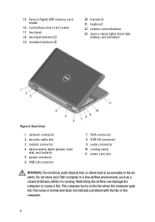
...) memory-card reader 16. touchpad buttons (2) 19. trackstick 21. Back View 1. USB 3.0 connector 9. Do not store your Dell computer in the air vents. Fan noise is running. touchpad 18. contactless smart card reader 17. keyboard 22. device status lights (hard disk, battery, and wireless) Figure 4. device status lights (power, hard disk, and...
...) memory-card reader 16. touchpad buttons (2) 19. trackstick 21. Back View 1. USB 3.0 connector 9. Do not store your Dell computer in the air vents. Fan noise is running. touchpad 18. contactless smart card reader 17. keyboard 22. device status lights (hard disk, battery, and wireless) Figure 4. device status lights (power, hard disk, and...
User Manual
Page 5
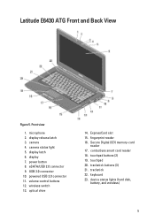
... status light 5. optical drive 14. trackstick buttons (3) 21. trackstick 22. display 7. fingerprint reader 16. device status lights (hard disk, battery, and wireless) 5 touchpad buttons (2) 19. Latitude E6430 ATG Front and Back View Figure 5. display latch 6. power button 8. wireless switch 13. Secure Digital (SD) memory-card reader 17. contactless smart card reader...
... status light 5. optical drive 14. trackstick buttons (3) 21. trackstick 22. display 7. fingerprint reader 16. device status lights (hard disk, battery, and wireless) 5 touchpad buttons (2) 19. Latitude E6430 ATG Front and Back View Figure 5. display latch 6. power button 8. wireless switch 13. Secure Digital (SD) memory-card reader 17. contactless smart card reader...
User Manual
Page 8
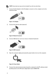
Connect USB devices, such as a mouse or keyboard (optional). Figure 8. USB Connector 4. NOTE: Some devices may not be included if you did not order them. 1. AC Adapter 2. Connect the network cable (optional). Connect ... connector on the computer. Open the computer display and press the power button to turn on the computer and to the RF cable (provided by Dell) present on the RF board. (Applicable only for E6430 ATG) 8 Power Button 5. Connect the external antennae (purchased by customer) to the electrical outlet. Figure 10...
Connect USB devices, such as a mouse or keyboard (optional). Figure 8. USB Connector 4. NOTE: Some devices may not be included if you did not order them. 1. AC Adapter 2. Connect the network cable (optional). Connect ... connector on the computer. Open the computer display and press the power button to turn on the computer and to the RF cable (provided by Dell) present on the RF board. (Applicable only for E6430 ATG) 8 Power Button 5. Connect the external antennae (purchased by customer) to the electrical outlet. Figure 10...
Latitude E-Family Re-Imaging Guide
Page 20
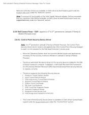
... the "Network" section 2.6.9 Dell Control Point - Dell Smart Card Keyboard 7. UPEK TouchChip Fingerprint Reader 8. In addition, it is available on Dell's driver & downloads support web site (support.dell.com) under the "Control Point" section Broadcom Trusted Platform Module 2. Winbond Trusted Platform Module 5. STMicroelectronics Trusted Platform Module 4. DCP, (applies to 1st & 2nd generations Latitude E-Family & Mobile Precision...
... the "Network" section 2.6.9 Dell Control Point - Dell Smart Card Keyboard 7. UPEK TouchChip Fingerprint Reader 8. In addition, it is available on Dell's driver & downloads support web site (support.dell.com) under the "Control Point" section Broadcom Trusted Platform Module 2. Winbond Trusted Platform Module 5. STMicroelectronics Trusted Platform Module 4. DCP, (applies to 1st & 2nd generations Latitude E-Family & Mobile Precision...
Latitude E-Family Re-Imaging Guide
Page 21
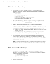
...and beyond) o For Ambient Light Sensor (ALS), install the Dell Ambient Light Sensor Utility component of power management configuring and alerting capabilities: o Battery Status o Power Scheme and Sleep Mode o Display and Devices o Keyboard Backlighting and Hotkeys Customization o Extended Battery Life / All Day ... Refer to Table B1 under "Control Point" section - Dell Latitude E-Family & Mobile Precision Reimage "How-To" Guide 2.6.9.2 Control Point System Manager o Dell Control Point System Manager module is a Dell developed modular application providing a complete set of Control Point in...
...and beyond) o For Ambient Light Sensor (ALS), install the Dell Ambient Light Sensor Utility component of power management configuring and alerting capabilities: o Battery Status o Power Scheme and Sleep Mode o Display and Devices o Keyboard Backlighting and Hotkeys Customization o Extended Battery Life / All Day ... Refer to Table B1 under "Control Point" section - Dell Latitude E-Family & Mobile Precision Reimage "How-To" Guide 2.6.9.2 Control Point System Manager o Dell Control Point System Manager module is a Dell developed modular application providing a complete set of Control Point in...
Latitude E-Family Re-Imaging Guide
Page 22
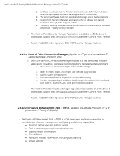
...Table B2 under Appendix-B for hot keys and system events Dell customized power plans and extensions Battery Health Information Touch Panel Keyboard hotkey information, including backlighting Smart Settings The Control Point Connection ...Security Manager Application is offered to Latitude Precision 3rd & 4th generation E-Family & Mobile) o Dell Feature Enhancement Pack - Dell Latitude E-Family & Mobile Precision Reimage "How-To" Guide 1. The security software stack can be obtained through Dell's support website 4. Control Point Security...
...Table B2 under Appendix-B for hot keys and system events Dell customized power plans and extensions Battery Health Information Touch Panel Keyboard hotkey information, including backlighting Smart Settings The Control Point Connection ...Security Manager Application is offered to Latitude Precision 3rd & 4th generation E-Family & Mobile) o Dell Feature Enhancement Pack - Dell Latitude E-Family & Mobile Precision Reimage "How-To" Guide 1. The security software stack can be obtained through Dell's support website 4. Control Point Security...
Latitude E-Family Re-Imaging Guide
Page 39
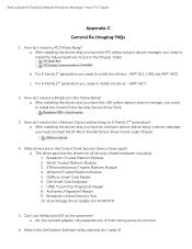
... the Chipset folder: b. Atmel Trusted Platform Module 3. No, the wireless adapter only supports one of them being active at the same time? Dell Latitude E-Family & Mobile Precision Reimage "How-To" Guide Appendix C General Re-Imaging FAQs 1. After installing the drivers and you have this USH... E-Family 2nd generation you need to install the ST Micro Freefall Sensor driver found in the Control Point Security Device Driver pack? Dell Smart Card Keyboard 7. After installing the drivers and you have an unknown device yellow bang in device manager, you need to install one time 6....
... the Chipset folder: b. Atmel Trusted Platform Module 3. No, the wireless adapter only supports one of them being active at the same time? Dell Latitude E-Family & Mobile Precision Reimage "How-To" Guide Appendix C General Re-Imaging FAQs 1. After installing the drivers and you have this USH... E-Family 2nd generation you need to install the ST Micro Freefall Sensor driver found in the Control Point Security Device Driver pack? Dell Smart Card Keyboard 7. After installing the drivers and you have an unknown device yellow bang in device manager, you need to install one time 6....
Latitude E-Family Re-Imaging Guide
Page 41
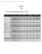
Dell Latitude E-Family & Mobile Precision Reimage "How-To" Guide Appendix D ...Desktops presence (PWS only) Reporting of SMART Alerts log information at OS presence (PWS only) Privacy Screen - Keyboard backlighting options (to be able to set to enale/disable ALS Feedback through BIOS Yes No (some Broadcom ... Power Manager Display settings Function Keys Hot Key customizaton Keyboard backlighting Brightness ALS Feature user profiles View battery manufacturer info. N/A N/A N/A N/A Yes (Intel LOM) Availabilty of Feature when Dell provides drivers/middleware, but with No screen pop-up...
Dell Latitude E-Family & Mobile Precision Reimage "How-To" Guide Appendix D ...Desktops presence (PWS only) Reporting of SMART Alerts log information at OS presence (PWS only) Privacy Screen - Keyboard backlighting options (to be able to set to enale/disable ALS Feedback through BIOS Yes No (some Broadcom ... Power Manager Display settings Function Keys Hot Key customizaton Keyboard backlighting Brightness ALS Feature user profiles View battery manufacturer info. N/A N/A N/A N/A Yes (Intel LOM) Availabilty of Feature when Dell provides drivers/middleware, but with No screen pop-up...

Owners Manual
Page 3
... the Subscriber Identity Module (SIM) Card 13 Removing the Base Cover...13 Installing the Base Cover...14 Removing the Keyboard Trim...14 Installing the Keyboard Trim...15 Removing the Keyboard...15 Installing the Keyboard...17 Removing the Hard Drive...17 Installing the Hard Drive...19 Removing the Optical Drive...19 Installing the Optical Drive...
... the Subscriber Identity Module (SIM) Card 13 Removing the Base Cover...13 Installing the Base Cover...14 Removing the Keyboard Trim...14 Installing the Keyboard Trim...15 Removing the Keyboard...15 Installing the Keyboard...17 Removing the Hard Drive...17 Installing the Hard Drive...19 Removing the Optical Drive...19 Installing the Optical Drive...

Owners Manual
Page 14
Place the base cover to the computer. 3. Follow the procedures in After Working Inside Your Computer. Remove the battery. 3. Installing the Base Cover 1. Tighten the screws to secure the base cover to align with the screw holes on the computer. 2. Using a plastic scribe, pry under the keyboard trim to remove it from the computer. Follow the procedures in Before Working Inside Your Computer. 2. Pry the keyboard trim along the sides and bottom. 14 Removing the Keyboard Trim 1. 3. Lift the base cover to release it from the computer. 4. Install the battery. 4.
Place the base cover to the computer. 3. Follow the procedures in After Working Inside Your Computer. Remove the battery. 3. Installing the Base Cover 1. Tighten the screws to secure the base cover to align with the screw holes on the computer. 2. Using a plastic scribe, pry under the keyboard trim to remove it from the computer. Follow the procedures in Before Working Inside Your Computer. 2. Pry the keyboard trim along the sides and bottom. 14 Removing the Keyboard Trim 1. 3. Lift the base cover to release it from the computer. 4. Install the battery. 4.

Owners Manual
Page 15
Press along the sides of the keyboard trim until it snaps in Before Working Inside Your Computer. 2. Follow the procedures in place. 3. Removing the Keyboard 1. Remove the screws that secure the keyboard to the palmrest assembly. 15 Remove: a) battery b) keyboard trim 3. Align the keyboard trim to remove the keyboard trim from the unit. Follow the procedures in After Working Inside Your Computer. Installing the Keyboard Trim 1. Install the battery. 4. Remove the screws that secure the keyboard to computer. 4. Lift up to its compartment. 2. 5.
Press along the sides of the keyboard trim until it snaps in Before Working Inside Your Computer. 2. Follow the procedures in place. 3. Removing the Keyboard 1. Remove the screws that secure the keyboard to the palmrest assembly. 15 Remove: a) battery b) keyboard trim 3. Align the keyboard trim to remove the keyboard trim from the unit. Follow the procedures in After Working Inside Your Computer. Installing the Keyboard Trim 1. Install the battery. 4. Remove the screws that secure the keyboard to computer. 4. Lift up to its compartment. 2. 5.

Owners Manual
Page 16
Peel back the adhesive tape securing the keyboard connector. 16 Lift and turn the keyboard to access the keyboard cable. 6. 5. Disconnect the keyboard cable from the computer. 8. Remove the keyboard from the system board. 7.
Peel back the adhesive tape securing the keyboard connector. 16 Lift and turn the keyboard to access the keyboard cable. 6. 5. Disconnect the keyboard cable from the computer. 8. Remove the keyboard from the system board. 7.

Owners Manual
Page 17
... the procedures in After Working Inside Your Computer. Connect the keyboard cable and secure it clicks into its compartment and ensure that secure the hard drive to the computer. 17 Installing the Keyboard 1. Removing the Hard Drive 1. Follow the procedures in Before... Working Inside Your Computer. 2. 9. Slide the keyboard into place. 4. Flip the computer and tighten the screws to the keyboard using the tape. 2. Remove the battery. 3. Remove the keyboard cable from the keyboard. Install: a) keyboard trim...
... the procedures in After Working Inside Your Computer. Connect the keyboard cable and secure it clicks into its compartment and ensure that secure the hard drive to the computer. 17 Installing the Keyboard 1. Removing the Hard Drive 1. Follow the procedures in Before... Working Inside Your Computer. 2. 9. Slide the keyboard into place. 4. Flip the computer and tighten the screws to the keyboard using the tape. 2. Remove the battery. 3. Remove the keyboard cable from the keyboard. Install: a) keyboard trim...

Owners Manual
Page 29
Remove the speaker cable from the routing channel. 29 Remove the screws that secure the speakers to the computer. 4. Removing the Speakers 1. Remove: a) battery b) base cover c) hard drive d) keyboard trim e) keyboard f) display assembly g) palmrest h) media board (available in Before Working Inside Your Computer. 2. Follow the procedures in E6430/E6430 ATG only) i) ExpressCard cage j) bluetooth card k) system board 3.
Remove the speaker cable from the routing channel. 29 Remove the screws that secure the speakers to the computer. 4. Removing the Speakers 1. Remove: a) battery b) base cover c) hard drive d) keyboard trim e) keyboard f) display assembly g) palmrest h) media board (available in Before Working Inside Your Computer. 2. Follow the procedures in E6430/E6430 ATG only) i) ExpressCard cage j) bluetooth card k) system board 3.

Owners Manual
Page 30
Installing the Speakers 1. 5. Align the speakers in E6430/E6430 ATG only) e) palmrest f) display assembly g) keyboard h) keyboard trim i) hard drive j) base cover k) battery 4. Remove: a) battery b) base cover 3. Tighten the screws to secure the speakers. 3. Install: a) system board b) bluetooth card c) ExpressCard cage d) media ...
Installing the Speakers 1. 5. Align the speakers in E6430/E6430 ATG only) e) palmrest f) display assembly g) keyboard h) keyboard trim i) hard drive j) base cover k) battery 4. Remove: a) battery b) base cover 3. Tighten the screws to secure the speakers. 3. Install: a) system board b) bluetooth card c) ExpressCard cage d) media ...

Owners Manual
Page 31
... cable. 3. Removing the ExpressCard Cage 1. Place the coin-cell battery in After Working Inside Your Computer. Remove: a) battery b) base cover c) hard drive d) bluetooth card e) keyboard trim f) keyboard g) display assembly h) palmrest 3. Remove the screws that secure the ExpressCard cage to the computer. 31 Pry the coin-cell battery upward and remove it from...
... cable. 3. Removing the ExpressCard Cage 1. Place the coin-cell battery in After Working Inside Your Computer. Remove: a) battery b) base cover c) hard drive d) bluetooth card e) keyboard trim f) keyboard g) display assembly h) palmrest 3. Remove the screws that secure the ExpressCard cage to the computer. 31 Pry the coin-cell battery upward and remove it from...

Owners Manual
Page 32
... the system board. 32 Follow the procedures in After Working Inside Your Computer. Disconnect the power-connector cable from the computer. Install: a) palmrest b) display assembly c) keyboard d) keyboard trim e) bluetooth card f) hard drive g) base cover h) battery 4. Follow the procedures in Before Working Inside Your Computer. 2.
... the system board. 32 Follow the procedures in After Working Inside Your Computer. Disconnect the power-connector cable from the computer. Install: a) palmrest b) display assembly c) keyboard d) keyboard trim e) bluetooth card f) hard drive g) base cover h) battery 4. Follow the procedures in Before Working Inside Your Computer. 2.

Owners Manual
Page 34
Disconnect the power LED board cable. 4. Remove the screw securing the power LED board to the display assembly. 5. Follow the procedures in Before Working Inside Your Computer. 2. Remove: a) battery b) base cover c) hard drive d) bluetooth module e) keyboard trim f) keyboard g) display assembly h) display bezel i) display panel 3. Remove the power LED board from the display assembly. 34 Removing the Power LED Board 1.
Disconnect the power LED board cable. 4. Remove the screw securing the power LED board to the display assembly. 5. Follow the procedures in Before Working Inside Your Computer. 2. Remove: a) battery b) base cover c) hard drive d) bluetooth module e) keyboard trim f) keyboard g) display assembly h) display bezel i) display panel 3. Remove the power LED board from the display assembly. 34 Removing the Power LED Board 1.

Owners Manual
Page 35
... its compartment in Before Working Inside Your Computer. 2. Install: a) display panel b) display bezel c) display assembly d) keyboard e) keyboard trim f) bluetooth module g) hard drive h) base cover i) battery 5. Remove: a) battery b) base cover c) hard drive d) optical drive e) bluetooth card f) keyboard trim g) keyboard h) display assembly i) palmrest j) media board (available in After Working Inside Your Computer. Tighten the screw to...
... its compartment in Before Working Inside Your Computer. 2. Install: a) display panel b) display bezel c) display assembly d) keyboard e) keyboard trim f) bluetooth module g) hard drive h) base cover i) battery 5. Remove: a) battery b) base cover c) hard drive d) optical drive e) bluetooth card f) keyboard trim g) keyboard h) display assembly i) palmrest j) media board (available in After Working Inside Your Computer. Tighten the screw to...


