User Manual
Page 1
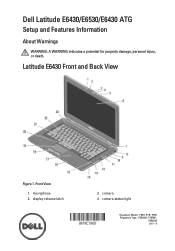
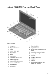
Dell Latitude E6430/E6530/E6430 ATG Setup and Features Information About Warnings WARNING: A WARNING indicates a potential for property damage, personal injury, or death. display release latch 3. camera 4. Front View 1. Latitude E6430 Front and Back View Figure 1. camera status light Regulatory Model: : P25G, P19F, P25G Regulatory Type: : P25G001, P19F001, P25G002 2011 - 9 microphone 2.
Dell Latitude E6430/E6530/E6430 ATG Setup and Features Information About Warnings WARNING: A WARNING indicates a potential for property damage, personal injury, or death. display release latch 3. camera 4. Front View 1. Latitude E6430 Front and Back View Figure 1. camera status light Regulatory Model: : P25G, P19F, P25G Regulatory Type: : P25G001, P19F001, P25G002 2011 - 9 microphone 2.
User Manual
Page 2
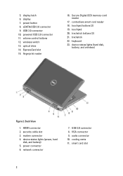
eSATA/USB 2.0 connector 9. USB 3.0 connector 10. trackstick 22. keyboard 23. power connector 6. USB 2.0 connector 8. display 7. optical drive 14. Secure Digital (SD) memory-card reader 17. HDMI connector 2. VGA connector 9. contactless smart card reader 18. smart card slot 2 powered USB 3.0 ... status lights (hard disk, battery, and wireless) Figure 2. fingerprint reader 16. touchpad 20. device status lights (power, hard disk, and battery) 5. wireless switch 13. display latch 6. modem connector 4. audio connector 10. 5. network connector 7.
eSATA/USB 2.0 connector 9. USB 3.0 connector 10. trackstick 22. keyboard 23. power connector 6. USB 2.0 connector 8. display 7. optical drive 14. Secure Digital (SD) memory-card reader 17. HDMI connector 2. VGA connector 9. contactless smart card reader 18. smart card slot 2 powered USB 3.0 ... status lights (hard disk, battery, and wireless) Figure 2. fingerprint reader 16. touchpad 20. device status lights (power, hard disk, and battery) 5. wireless switch 13. display latch 6. modem connector 4. audio connector 10. 5. network connector 7.
User Manual
Page 3
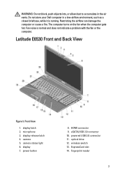
display latch 2. power button 8. ExpressCard slot 14. Restricting the airflow can damage the computer or cause a fire. Front View 1. fingerprint reader 3 WARNING: Do not block, push ... the fan or the computer. The computer turns on the fan when the computer gets hot. Latitude E6530 Front and Back View Figure 3. microphone 3. display release latch 4. eSATA/USB 2.0 connector 10. wireless switch 13. Do not store your Dell computer in the air vents. Fan noise is running. camera 5. optical drive 12. powered USB...
display latch 2. power button 8. ExpressCard slot 14. Restricting the airflow can damage the computer or cause a fire. Front View 1. fingerprint reader 3 WARNING: Do not block, push ... the fan or the computer. The computer turns on the fan when the computer gets hot. Latitude E6530 Front and Back View Figure 3. microphone 3. display release latch 4. eSATA/USB 2.0 connector 10. wireless switch 13. Do not store your Dell computer in the air vents. Fan noise is running. camera 5. optical drive 12. powered USB...
User Manual
Page 5
Latitude E6430 ATG Front and Back View Figure 5. display release latch 3. powered USB 3.0 connector 11. wireless switch 13. fingerprint reader 16. Secure Digital (SD) memory-card reader 17. contactless smart card reader... lights (hard disk, battery, and wireless) 5 power button 8. ExpressCard slot 15. touchpad 20. eSATA/USB 2.0 connector 9. touchpad buttons (2) 19. keyboard 23. camera 4. display latch 6. Front view 1. volume control buttons 12. camera status light 5. optical drive 14. trackstick buttons (3) 21. USB 3.0 connector 10. microphone...
Latitude E6430 ATG Front and Back View Figure 5. display release latch 3. powered USB 3.0 connector 11. wireless switch 13. fingerprint reader 16. Secure Digital (SD) memory-card reader 17. contactless smart card reader... lights (hard disk, battery, and wireless) 5 power button 8. ExpressCard slot 15. touchpad 20. eSATA/USB 2.0 connector 9. touchpad buttons (2) 19. keyboard 23. camera 4. display latch 6. Front view 1. volume control buttons 12. camera status light 5. optical drive 14. trackstick buttons (3) 21. USB 3.0 connector 10. microphone...
User Manual
Page 8
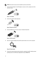
... Network Connector 3. USB Connector 4. Connect the AC adapter to the AC adapter connector on the computer and to the RF cable (provided by Dell) present on the computer. AC Adapter 2. Power Button 5. Connect the external antennae (purchased by customer) to the electrical outlet. Connect the ...network cable (optional). Open the computer display and press the power button to turn on the RF board. (Applicable only for E6430 ATG) 8 Figure 8. Figure 10. NOTE: Some ...
... Network Connector 3. USB Connector 4. Connect the AC adapter to the AC adapter connector on the computer and to the RF cable (provided by Dell) present on the computer. AC Adapter 2. Power Button 5. Connect the external antennae (purchased by customer) to the electrical outlet. Connect the ...network cable (optional). Open the computer display and press the power button to turn on the RF board. (Applicable only for E6430 ATG) 8 Figure 8. Figure 10. NOTE: Some ...
Intel Responsiveness Technologies Guide
Page 32
...seconds. If the Rapid Start Manager application (described below) is installed and the feature is disabled in BIOS, it would in Windows. The Dell Latitude system BIOS menu location for Rapid Start settings. • Settings • Intel Rapid Start Enable: The Rapid Start menu contains a main enable...indicator will turn on to indicate that puts the system into Rapid Start low-power mode during system power-up, while the Dell logo is displayed. Dell Setup Guide Other systems may be off. During this setting hides the device from Windows, disabling Rapid Start will defeat the...
...seconds. If the Rapid Start Manager application (described below) is installed and the feature is disabled in BIOS, it would in Windows. The Dell Latitude system BIOS menu location for Rapid Start settings. • Settings • Intel Rapid Start Enable: The Rapid Start menu contains a main enable...indicator will turn on to indicate that puts the system into Rapid Start low-power mode during system power-up, while the Dell logo is displayed. Dell Setup Guide Other systems may be off. During this setting hides the device from Windows, disabling Rapid Start will defeat the...
Statement of Volatility
Page 1
...U51 Flash in JDIMMB text). Table 1. Stores panel assembly manufacturing information and display configuration data. One device one or two present on the Dell Latitude™ E6230/E6330/E6430/E6430ATG/E6530 system board. One or both volatile and non-volatile (NV) components. ...manufacturer data and timing information for embedded controller BIOS code, asset tag, and BIOS passwords. The Dell Latitude™ E6230/E6330/E6430/E6430ATG/E6530 contains both modules will be populated. The following NV components are present on each SoDIMM. System BIOS...
...U51 Flash in JDIMMB text). Table 1. Stores panel assembly manufacturing information and display configuration data. One device one or two present on the Dell Latitude™ E6230/E6330/E6430/E6430ATG/E6530 system board. One or both volatile and non-volatile (NV) components. ...manufacturer data and timing information for embedded controller BIOS code, asset tag, and BIOS passwords. The Dell Latitude™ E6230/E6330/E6430/E6430ATG/E6530 contains both modules will be populated. The following NV components are present on each SoDIMM. System BIOS...
Latitude E-Family Re-Imaging Guide
Page 6
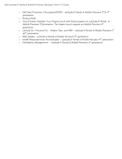
... Ten fingers touch support on Latitude E-Family & Mobile Precision 3rdgeneration. o Latitude On / Precision On - Latitude E-Family & Mobile Precision 4th generation o Intel® Responsiveness Technologies - Dell Latitude E-Family & Mobile Precision Reimage "How-To" Guide o Dell Data Protection | Encryption(DDPE) - Four Fingers touch with Stylus support on Mobile Precision 4th generation. Latitude E-Family & Mobile Precision 1st &2nd generation o WiDi display -
... Ten fingers touch support on Latitude E-Family & Mobile Precision 3rdgeneration. o Latitude On / Precision On - Latitude E-Family & Mobile Precision 4th generation o Intel® Responsiveness Technologies - Dell Latitude E-Family & Mobile Precision Reimage "How-To" Guide o Dell Data Protection | Encryption(DDPE) - Four Fingers touch with Stylus support on Mobile Precision 4th generation. Latitude E-Family & Mobile Precision 1st &2nd generation o WiDi display -
Latitude E-Family Re-Imaging Guide
Page 21
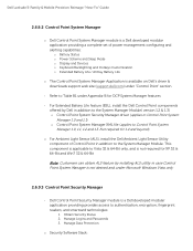
... Scheme and Sleep Mode o Display and Devices o Keyboard Backlighting and Hotkeys Customization o Extended Battery Life / All Day Battery Life o The Control Point System Manager Application is applicable to Control Point System Manager 1.0, 1.1, 1.2 and 1.3. Dell Latitude E-Family & Mobile Precision Reimage... "How-To" Guide 2.6.9.2 Control Point System Manager o Dell Control Point System Manager module is a Dell developed modular application providing a complete set of Control Point ...
... Scheme and Sleep Mode o Display and Devices o Keyboard Backlighting and Hotkeys Customization o Extended Battery Life / All Day Battery Life o The Control Point System Manager Application is applicable to Control Point System Manager 1.0, 1.1, 1.2 and 1.3. Dell Latitude E-Family & Mobile Precision Reimage... "How-To" Guide 2.6.9.2 Control Point System Manager o Dell Control Point System Manager module is a Dell developed modular application providing a complete set of Control Point ...
Latitude E-Family Re-Imaging Guide
Page 24
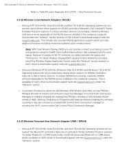
... controllers featured on Latitude E-Family & Mobile Precision systems. To obtain Bluetooth or UWB functionality, install the associated Bluetooth or UWB device drivers available on Dell's driver & downloads support web site (support.dell.com). Because it's based on Dell's driver & downloads support web site (support.dell.com) under the "Network" section To obtain Wireless Display(ONLY applied...
... controllers featured on Latitude E-Family & Mobile Precision systems. To obtain Bluetooth or UWB functionality, install the associated Bluetooth or UWB device drivers available on Dell's driver & downloads support web site (support.dell.com). Because it's based on Dell's driver & downloads support web site (support.dell.com) under the "Network" section To obtain Wireless Display(ONLY applied...
Latitude E-Family Re-Imaging Guide
Page 41
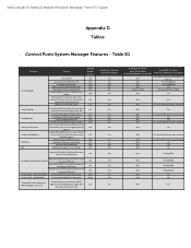
Dell Latitude E-Family & Mobile Precision Reimage "How-To" Guide Appendix D Tables - Discreet Graphics Fn+E to toggle display by default). N/A N/A N/A N/A Yes (Intel LOM) Availabilty of Feature when DCP Installed? battery charge enable/disable status Network card power management Extended Battery Life/ All Day Battery Life. (ADBL) Dell...Availablity of ECC Alerts log information at OS presence (PWS only) Reporting of Feature when Dell provides drivers/middleware, but with No screen pop-up display Yes N/A No Yes N/A Yes Yes N/A No Yes N/A Through BIOS Yes N/A ...
Dell Latitude E-Family & Mobile Precision Reimage "How-To" Guide Appendix D Tables - Discreet Graphics Fn+E to toggle display by default). N/A N/A N/A N/A Yes (Intel LOM) Availabilty of Feature when DCP Installed? battery charge enable/disable status Network card power management Extended Battery Life/ All Day Battery Life. (ADBL) Dell...Availablity of ECC Alerts log information at OS presence (PWS only) Reporting of Feature when Dell provides drivers/middleware, but with No screen pop-up display Yes N/A No Yes N/A Yes Yes N/A No Yes N/A Through BIOS Yes N/A ...

Owners Manual
Page 4
... Connector...47 Removing the Display Assembly...47 Installing the Display Assembly...49 Removing the Display Bezel...50 Installing the Display Bezel...50 Removing the Display Panel...51 Installing the Display Panel...52 Removing the Display Assembly...52 Installing the Display Assembly...54 Removing the Display-Hinge Caps...55 Installing the Display-Hinge Caps...55 Removing the Display Hinges...56 Installing the...
... Connector...47 Removing the Display Assembly...47 Installing the Display Assembly...49 Removing the Display Bezel...50 Installing the Display Bezel...50 Removing the Display Panel...51 Installing the Display Panel...52 Removing the Display Assembly...52 Installing the Display Assembly...54 Removing the Display-Hinge Caps...55 Installing the Display-Hinge Caps...55 Removing the Display Hinges...56 Installing the...

Owners Manual
Page 8
...the system board, you must remove the main battery before you shut down your computer from the electrical outlet before you work surface. Open the display. 10. Click Shut Down. While you turn them off your computer. 1. Turning Off Your Computer CAUTION: To avoid losing data, save and..., always unplug your operating system, press and hold the power button for about 4 seconds to ground the system board. or 1. Close the display and turn the computer upside-down the operating system: - Ensure that the computer and all open files and exit all attached devices are turned ...
...the system board, you must remove the main battery before you shut down your computer from the electrical outlet before you work surface. Open the display. 10. Click Shut Down. While you turn them off your computer. 1. Turning Off Your Computer CAUTION: To avoid losing data, save and..., always unplug your operating system, press and hold the power button for about 4 seconds to ground the system board. or 1. Close the display and turn the computer upside-down the operating system: - Ensure that the computer and all open files and exit all attached devices are turned ...

Owners Manual
Page 29
Remove the speaker cable from the routing channel. 29 Follow the procedures in E6430/E6430 ATG only) i) ExpressCard cage j) bluetooth card k) system board 3. Remove the screws that secure the speakers to the computer. 4. Remove: a) battery b) base cover c) hard drive d) keyboard trim e) keyboard f) display assembly g) palmrest h) media board (available in Before Working Inside Your Computer. 2. Removing the Speakers 1.
Remove the speaker cable from the routing channel. 29 Follow the procedures in E6430/E6430 ATG only) i) ExpressCard cage j) bluetooth card k) system board 3. Remove the screws that secure the speakers to the computer. 4. Remove: a) battery b) base cover c) hard drive d) keyboard trim e) keyboard f) display assembly g) palmrest h) media board (available in Before Working Inside Your Computer. 2. Removing the Speakers 1.

Owners Manual
Page 30
... d) media board (available in Before Working Inside Your Computer. 2. Disconnect the coin-cell battery cable. 30 Follow the procedures in E6430/E6430 ATG only) e) palmrest f) display assembly g) keyboard h) keyboard trim i) hard drive j) base cover k) battery 4. 5.
... d) media board (available in Before Working Inside Your Computer. 2. Disconnect the coin-cell battery cable. 30 Follow the procedures in E6430/E6430 ATG only) e) palmrest f) display assembly g) keyboard h) keyboard trim i) hard drive j) base cover k) battery 4. 5.

Owners Manual
Page 31
... coin-cell battery in Before Working Inside Your Computer. 2. Installing the Coin-Cell Battery 1. Remove: a) battery b) base cover c) hard drive d) bluetooth card e) keyboard trim f) keyboard g) display assembly h) palmrest 3. Remove the screws that secure the ExpressCard cage to the computer. 31 Install: a) base cover b) battery 4. Pry the coin-cell battery upward and...
... coin-cell battery in Before Working Inside Your Computer. 2. Installing the Coin-Cell Battery 1. Remove: a) battery b) base cover c) hard drive d) bluetooth card e) keyboard trim f) keyboard g) display assembly h) palmrest 3. Remove the screws that secure the ExpressCard cage to the computer. 31 Install: a) base cover b) battery 4. Pry the coin-cell battery upward and...

Owners Manual
Page 32
Place the ExpressCard cage into its compartment. 2. Install: a) palmrest b) display assembly c) keyboard d) keyboard trim e) bluetooth card f) hard drive g) base cover h) battery 4. Remove: a) battery b) base cover 3. Installing the ExpressCard Cage 1. Follow the procedures in Before Working ...
Place the ExpressCard cage into its compartment. 2. Install: a) palmrest b) display assembly c) keyboard d) keyboard trim e) bluetooth card f) hard drive g) base cover h) battery 4. Remove: a) battery b) base cover 3. Installing the ExpressCard Cage 1. Follow the procedures in Before Working ...

Owners Manual
Page 34
Removing the Power LED Board 1. Follow the procedures in Before Working Inside Your Computer. 2. Remove the power LED board from the display assembly. 34 Remove: a) battery b) base cover c) hard drive d) bluetooth module e) keyboard trim f) keyboard g) display assembly h) display bezel i) display panel 3. Remove the screw securing the power LED board to the display assembly. 5. Disconnect the power LED board cable. 4.
Removing the Power LED Board 1. Follow the procedures in Before Working Inside Your Computer. 2. Remove the power LED board from the display assembly. 34 Remove: a) battery b) base cover c) hard drive d) bluetooth module e) keyboard trim f) keyboard g) display assembly h) display bezel i) display panel 3. Remove the screw securing the power LED board to the display assembly. 5. Disconnect the power LED board cable. 4.

Owners Manual
Page 35
.... 3. Removing the Input/Output (I /O board to the computer. 35 Install: a) display panel b) display bezel c) display assembly d) keyboard e) keyboard trim f) bluetooth module g) hard drive h) base cover i) battery 5. Follow the procedures in E6430/E6430 ATG ... screw that secures the I /O) Board 1. Remove: a) battery b) base cover c) hard drive d) optical drive e) bluetooth card f) keyboard trim g) keyboard h) display assembly i) palmrest j) media board (available in Before Working Inside Your Computer. 2. Place the power LED board in its compartment in After Working Inside Your Computer...
.... 3. Removing the Input/Output (I /O board to the computer. 35 Install: a) display panel b) display bezel c) display assembly d) keyboard e) keyboard trim f) bluetooth module g) hard drive h) base cover i) battery 5. Follow the procedures in E6430/E6430 ATG ... screw that secures the I /O) Board 1. Remove: a) battery b) base cover c) hard drive d) optical drive e) bluetooth card f) keyboard trim g) keyboard h) display assembly i) palmrest j) media board (available in Before Working Inside Your Computer. 2. Place the power LED board in its compartment in After Working Inside Your Computer...

Owners Manual
Page 36
... system board b) ExpressCard cage c) media board (available in Before Working Inside Your Computer. 2. 4. Follow the procedures in E6430/E6430 ATG only) d) palmrest e) display assembly f) keyboard g) keyboard trim h) bluetooth card i) hard drive j) optical drive k) base cover l) battery 4. Removing the Hard-Drive Support Plate 1. Remove the ... /O board from the computer. Remove the: a) battery b) base cover c) hard drive d) optical drive e) keyboard trim f) keyboard g) display assembly h) palmrest 36 Installing the Input Output (I /O board in After Working Inside Your Computer.
... system board b) ExpressCard cage c) media board (available in Before Working Inside Your Computer. 2. 4. Follow the procedures in E6430/E6430 ATG only) d) palmrest e) display assembly f) keyboard g) keyboard trim h) bluetooth card i) hard drive j) optical drive k) base cover l) battery 4. Removing the Hard-Drive Support Plate 1. Remove the ... /O board from the computer. Remove the: a) battery b) base cover c) hard drive d) optical drive e) keyboard trim f) keyboard g) display assembly h) palmrest 36 Installing the Input Output (I /O board in After Working Inside Your Computer.


