Intel Responsiveness Technologies Guide
Page 15
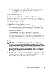
... • Enhanced mode: Acceleration is strongly discouraged. This improves write performance, but read operations will be simultaneously written to the hard drive to use Smart Response?" Depending on page 15 for Smart Response, the system will allow the cache to be properly flushed back... to use Smart Response? Once the system is configured for more details regarding Enhanced and Maximized modes. See "How to the hard drive. Disabling CAUTION: Deleting the Smart Response partition (!), or removing the Smart Response SSD cache device: Manually deleting/erasing the Smart ...
... • Enhanced mode: Acceleration is strongly discouraged. This improves write performance, but read operations will be simultaneously written to the hard drive to use Smart Response?" Depending on page 15 for Smart Response, the system will allow the cache to be properly flushed back... to use Smart Response? Once the system is configured for more details regarding Enhanced and Maximized modes. See "How to the hard drive. Disabling CAUTION: Deleting the Smart Response partition (!), or removing the Smart Response SSD cache device: Manually deleting/erasing the Smart ...
Statement of Volatility
Page 2
...are S0, S1, S3, S4, and S5): S0 state is the working state, a restore file from the system. DVD/ DVD+RW/ Diskette Drives Enter S3-S5 state below. Primary power loss (unplugging the power cord and removing the battery) destroys all system contexts. Secondary power loss (removing ...up-sell 128K byte ROM, 128K bit one-time No USH daughter programmable. Dell systems will write the system context to disk" state or "hibernate" mode. In this state, the dynamic RAM is not maintained. Hard drive User Non-volatile magnetic Yes replaceable media, various sizes in off state. If ...
...are S0, S1, S3, S4, and S5): S0 state is the working state, a restore file from the system. DVD/ DVD+RW/ Diskette Drives Enter S3-S5 state below. Primary power loss (unplugging the power cord and removing the battery) destroys all system contexts. Secondary power loss (removing ...up-sell 128K byte ROM, 128K bit one-time No USH daughter programmable. Dell systems will write the system context to disk" state or "hibernate" mode. In this state, the dynamic RAM is not maintained. Hard drive User Non-volatile magnetic Yes replaceable media, various sizes in off state. If ...
Latitude E-Family Re-Imaging Guide
Page 34
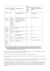
... hosts and will allow storage devices to 4KB sector HDDs will operate at 4KB. 2 How does an Advanced Format HDD impact OS Images? Dell Latitude E-Family & Mobile Precision Reimage "How-To" Guide Appendix B 512e / 4KBe HDD Re-image Guidelines 1 What is moving towards the Advanced... limitations with the 512-byte sector HDDs, the industry is moving towards supporting higher drives capacity, to be required to optimize the performance of the Advanced Format technology. While hard drives will transition to 4KB sectors and to maintain backwards compatibility, current Advanced Format 4KB HDDs...
... hosts and will allow storage devices to 4KB sector HDDs will operate at 4KB. 2 How does an Advanced Format HDD impact OS Images? Dell Latitude E-Family & Mobile Precision Reimage "How-To" Guide Appendix B 512e / 4KBe HDD Re-image Guidelines 1 What is moving towards the Advanced... limitations with the 512-byte sector HDDs, the industry is moving towards supporting higher drives capacity, to be required to optimize the performance of the Advanced Format technology. While hard drives will transition to 4KB sectors and to maintain backwards compatibility, current Advanced Format 4KB HDDs...
Latitude E-Family Re-Imaging Guide
Page 37
... to ensure Advanced Format drive partitions are properly aligned before encrypting the drive. Note: Misaligned encrypted Advanced Format drives need to be used to ensure alignment when deployed to insure proper hard drive performance and imaging between drives of OS: - If...Ghost: Ghost 11.5 will remain aligned. Dell Latitude E-Family & Mobile Precision Reimage "How-To" Guide 3.3 Other Partition Alignment Requirements Environment Action IRRT / RAID 0,1 & 5 Configuration Use Alignment Tools(1) to ensure Advanced Format drive partitions are properly aligned Data Protection / ...
... to ensure Advanced Format drive partitions are properly aligned before encrypting the drive. Note: Misaligned encrypted Advanced Format drives need to be used to ensure alignment when deployed to insure proper hard drive performance and imaging between drives of OS: - If...Ghost: Ghost 11.5 will remain aligned. Dell Latitude E-Family & Mobile Precision Reimage "How-To" Guide 3.3 Other Partition Alignment Requirements Environment Action IRRT / RAID 0,1 & 5 Configuration Use Alignment Tools(1) to ensure Advanced Format drive partitions are properly aligned Data Protection / ...

Owners Manual
Page 3
... Removing the Keyboard Trim...14 Installing the Keyboard Trim...15 Removing the Keyboard...15 Installing the Keyboard...17 Removing the Hard Drive...17 Installing the Hard Drive...19 Removing the Optical Drive...19 Installing the Optical Drive...21 Removing the Memory...21 Installing the Memory...22 Removing the Processor...22 Installing the Processor...23 Removing the...
... Removing the Keyboard Trim...14 Installing the Keyboard Trim...15 Removing the Keyboard...15 Installing the Keyboard...17 Removing the Hard Drive...17 Installing the Hard Drive...19 Removing the Optical Drive...19 Installing the Optical Drive...21 Removing the Memory...21 Installing the Memory...22 Removing the Processor...22 Installing the Processor...23 Removing the...

Owners Manual
Page 4
... Board...34 Installing the Power LED Board...35 Removing the Input/Output (I/O) Board...35 Installing the Input Output (I/O) Board...36 Removing the Hard-Drive Support Plate...36 Installing the Hard-Drive Support Plate...37 Removing the Palmrest...37 Installing the Palmrest...39 Removing the WiFi-Switch Board...40 Installing the WiFi-Switch Board...41...
... Board...34 Installing the Power LED Board...35 Removing the Input/Output (I/O) Board...35 Installing the Input Output (I/O) Board...36 Removing the Hard-Drive Support Plate...36 Installing the Hard-Drive Support Plate...37 Removing the Palmrest...37 Installing the Palmrest...39 Removing the WiFi-Switch Board...40 Installing the WiFi-Switch Board...41...

Owners Manual
Page 17
... trim b) battery 7. Installing the Keyboard 1. Connect the keyboard cable and secure it clicks into its compartment and ensure that secure the hard drive to the computer. 17 Follow the procedures in Before Working Inside Your Computer. 2. Remove the battery. 3. Remove the screws that it... to secure the keyboard on the palmrest. 5. Flip the computer and tighten the screws to the system board. 3. Removing the Hard Drive 1. Slide the keyboard into place. 4. Follow the procedures in After Working Inside Your Computer. 9. Tighten the screws to the keyboard ...
... trim b) battery 7. Installing the Keyboard 1. Connect the keyboard cable and secure it clicks into its compartment and ensure that secure the hard drive to the computer. 17 Follow the procedures in Before Working Inside Your Computer. 2. Remove the battery. 3. Remove the screws that it... to secure the keyboard on the palmrest. 5. Flip the computer and tighten the screws to the system board. 3. Removing the Hard Drive 1. Slide the keyboard into place. 4. Follow the procedures in After Working Inside Your Computer. 9. Tighten the screws to the keyboard ...

Owners Manual
Page 18
4. Remove the hard-drive caddy from the hard drive. 18 Remove the hard-drive isolation from the hard drive. 7. Remove the screw that secures the hard-drive caddy to the hard drive. 6. Slide the hard drive out of the computer. 5.
4. Remove the hard-drive caddy from the hard drive. 18 Remove the hard-drive isolation from the hard drive. 7. Remove the screw that secures the hard-drive caddy to the hard drive. 6. Slide the hard drive out of the computer. 5.

Owners Manual
Page 19
... the procedures in After Working Inside Your Computer. Installing the Hard Drive 1. Install the hard-drive isolation on the hard drive. 2. Remove the battery. 3. Tighten the screws to secure the hard drive to the hard drive. 4. Press the optical-drive latch to the hard drive. 3. Slide the hard drive into the computer. 5. Follow the procedures in Before Working Inside Your Computer. 2. Tighten the screws to...
... the procedures in After Working Inside Your Computer. Installing the Hard Drive 1. Install the hard-drive isolation on the hard drive. 2. Remove the battery. 3. Tighten the screws to secure the hard drive to the hard drive. 4. Press the optical-drive latch to the hard drive. 3. Slide the hard drive into the computer. 5. Follow the procedures in Before Working Inside Your Computer. 2. Tighten the screws to...

Owners Manual
Page 29
Removing the Speakers 1. Follow the procedures in E6430/E6430 ATG only) i) ExpressCard cage j) bluetooth card k) system board 3. Remove the speaker cable from the routing channel. 29 Remove: a) battery b) base cover c) hard drive d) keyboard trim e) keyboard f) display assembly g) palmrest h) media board (available in Before Working Inside Your Computer. 2. Remove the screws that secure the speakers to the computer. 4.
Removing the Speakers 1. Follow the procedures in E6430/E6430 ATG only) i) ExpressCard cage j) bluetooth card k) system board 3. Remove the speaker cable from the routing channel. 29 Remove: a) battery b) base cover c) hard drive d) keyboard trim e) keyboard f) display assembly g) palmrest h) media board (available in Before Working Inside Your Computer. 2. Remove the screws that secure the speakers to the computer. 4.

Owners Manual
Page 30
... connect the speaker cables. 2. Disconnect the coin-cell battery cable. 30 5. Follow the procedures in E6430/E6430 ATG only) e) palmrest f) display assembly g) keyboard h) keyboard trim i) hard drive j) base cover k) battery 4. Remove the speakers from the computer. Installing the Speakers 1. Install: a) system board b) bluetooth card c) ExpressCard cage d) media board (available in After Working...
... connect the speaker cables. 2. Disconnect the coin-cell battery cable. 30 5. Follow the procedures in E6430/E6430 ATG only) e) palmrest f) display assembly g) keyboard h) keyboard trim i) hard drive j) base cover k) battery 4. Remove the speakers from the computer. Installing the Speakers 1. Install: a) system board b) bluetooth card c) ExpressCard cage d) media board (available in After Working...

Owners Manual
Page 31
Place the coin-cell battery in After Working Inside Your Computer. Follow the procedures in its slot. 2. Remove: a) battery b) base cover c) hard drive d) bluetooth card e) keyboard trim f) keyboard g) display assembly h) palmrest 3. Removing the ExpressCard Cage 1. Pry the coin-cell battery upward and remove it from the computer. Follow ...
Place the coin-cell battery in After Working Inside Your Computer. Follow the procedures in its slot. 2. Remove: a) battery b) base cover c) hard drive d) bluetooth card e) keyboard trim f) keyboard g) display assembly h) palmrest 3. Removing the ExpressCard Cage 1. Pry the coin-cell battery upward and remove it from the computer. Follow ...

Owners Manual
Page 32
... from the system board. 32 Tighten the screws to secure the ExpressCard cage to the computer. 3. Install: a) palmrest b) display assembly c) keyboard d) keyboard trim e) bluetooth card f) hard drive g) base cover h) battery 4. Removing the Power-Connector Port 1. Place the ExpressCard cage into its compartment. 2. Follow the procedures in Before Working Inside Your Computer. 2. 4. Installing...
... from the system board. 32 Tighten the screws to secure the ExpressCard cage to the computer. 3. Install: a) palmrest b) display assembly c) keyboard d) keyboard trim e) bluetooth card f) hard drive g) base cover h) battery 4. Removing the Power-Connector Port 1. Place the ExpressCard cage into its compartment. 2. Follow the procedures in Before Working Inside Your Computer. 2. 4. Installing...

Owners Manual
Page 34
Remove the power LED board from the display assembly. 34 Remove: a) battery b) base cover c) hard drive d) bluetooth module e) keyboard trim f) keyboard g) display assembly h) display bezel i) display panel 3. Removing the Power LED Board 1. Disconnect the power LED board cable. 4. Remove the screw securing the power LED board to the display assembly. 5. Follow the procedures in Before Working Inside Your Computer. 2.
Remove the power LED board from the display assembly. 34 Remove: a) battery b) base cover c) hard drive d) bluetooth module e) keyboard trim f) keyboard g) display assembly h) display bezel i) display panel 3. Removing the Power LED Board 1. Disconnect the power LED board cable. 4. Remove the screw securing the power LED board to the display assembly. 5. Follow the procedures in Before Working Inside Your Computer. 2.

Owners Manual
Page 35
...to the display assembly. 4. Follow the procedures in E6430/E6430 ATG only) k) ExpressCard cage l) system board 3. Remove: a) battery b) base cover c) hard drive d) optical drive e) bluetooth card f) keyboard trim g) keyboard h) display assembly i) palmrest j) media board (available in Before Working Inside Your Computer. 2. Installing the Power ...Inside Your Computer. Install: a) display panel b) display bezel c) display assembly d) keyboard e) keyboard trim f) bluetooth module g) hard drive h) base cover i) battery 5. Removing the Input/Output (I /O board to the computer. 35
...to the display assembly. 4. Follow the procedures in E6430/E6430 ATG only) k) ExpressCard cage l) system board 3. Remove: a) battery b) base cover c) hard drive d) optical drive e) bluetooth card f) keyboard trim g) keyboard h) display assembly i) palmrest j) media board (available in Before Working Inside Your Computer. 2. Installing the Power ...Inside Your Computer. Install: a) display panel b) display bezel c) display assembly d) keyboard e) keyboard trim f) bluetooth module g) hard drive h) base cover i) battery 5. Removing the Input/Output (I /O board to the computer. 35

Owners Manual
Page 36
... Input Output (I /O board in After Working Inside Your Computer. Follow the procedures in E6430/E6430 ATG only) d) palmrest e) display assembly f) keyboard g) keyboard trim h) bluetooth card i) hard drive j) optical drive k) base cover l) battery 4. Follow the procedures in its compartment. 2. Tighten the screws to secure the I /O board from the computer. Remove the I /O board. 3. 4. Remove the...
... Input Output (I /O board in After Working Inside Your Computer. Follow the procedures in E6430/E6430 ATG only) d) palmrest e) display assembly f) keyboard g) keyboard trim h) bluetooth card i) hard drive j) optical drive k) base cover l) battery 4. Follow the procedures in its compartment. 2. Tighten the screws to secure the I /O board from the computer. Remove the I /O board. 3. 4. Remove the...

Owners Manual
Page 37
... 1. Install the: a) palmrest b) display assembly c) keyboard d) keyboard trim e) optical drive f) hard drive g) base cover h) battery 4. Place the hard-drive support plate in Before Working Inside Your Computer. 2. Tighten the screw to secure the hard drive support plate to the computer. 4. Follow the procedures in its compartment. 2. Lift the hard-drive support plate from the computer. Remove: a) battery b) base cover...
... 1. Install the: a) palmrest b) display assembly c) keyboard d) keyboard trim e) optical drive f) hard drive g) base cover h) battery 4. Place the hard-drive support plate in Before Working Inside Your Computer. 2. Tighten the screw to secure the hard drive support plate to the computer. 4. Follow the procedures in its compartment. 2. Lift the hard-drive support plate from the computer. Remove: a) battery b) base cover...
Owners Manual
Page 39
Align the palmrest assembly to the computer. 4. Lift and remove the palmrest from the computer. Connect the following cables: a) media board (available in After Working Inside Your Computer. 39 Follow the procedures in E6430/E6430 ATG only) b) touchpad c) fingerprint reader 3. Tighten the screws to secure the palmrest to its original position in the computer and snap it into place. 2. Installing the Palmrest 1. Install: a) keyboard b) keyboard trim c) bluetooth module d) hard drive e) base cover f) battery 5. 7. Disconnect the fingerprint reader cable. 8.
Align the palmrest assembly to the computer. 4. Lift and remove the palmrest from the computer. Connect the following cables: a) media board (available in After Working Inside Your Computer. 39 Follow the procedures in E6430/E6430 ATG only) b) touchpad c) fingerprint reader 3. Tighten the screws to secure the palmrest to its original position in the computer and snap it into place. 2. Installing the Palmrest 1. Install: a) keyboard b) keyboard trim c) bluetooth module d) hard drive e) base cover f) battery 5. 7. Disconnect the fingerprint reader cable. 8.

Owners Manual
Page 40
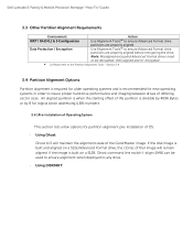
Follow the procedures in Before Working Inside Your Computer. 2. Peel of the adhesive tape on the back of the WiFi-switch board and remove the WiFi-switch board. 40 Remove the: a) battery b) base cover c) hard drive d) optical drive e) keyboard trim f) keyboard g) palmrest 3. Disconnect the WiFi-switch board cable from the system board. 4. Remove the screw that secures the WiFi-switch board. 5. Removing the WiFi-Switch Board 1.
Follow the procedures in Before Working Inside Your Computer. 2. Peel of the adhesive tape on the back of the WiFi-switch board and remove the WiFi-switch board. 40 Remove the: a) battery b) base cover c) hard drive d) optical drive e) keyboard trim f) keyboard g) palmrest 3. Disconnect the WiFi-switch board cable from the system board. 4. Remove the screw that secures the WiFi-switch board. 5. Removing the WiFi-Switch Board 1.

Owners Manual
Page 41
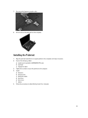
Install: a) palmrest b) keyboard c) keyboard trim d) optical drive e) hard drive f) base cover g) battery 5. Follow the procedures in After Working Inside Your Computer. Installing the WiFi-Switch Board 1. Fix the adhesive tape on the back .... 2. Tighten the screw to the system board. 4. Removing the System Board 1. Follow the procedures in Before Working Inside Your Computer. 2. Remove: a) battery b) base cover c) hard drive d) optical drive e) bluetooth card f) keyboard trim g) keyboard h) WLAN card i) modem card j) heat sink k) processor l) palmrest m) ExpressCard cage 3.
Install: a) palmrest b) keyboard c) keyboard trim d) optical drive e) hard drive f) base cover g) battery 5. Follow the procedures in After Working Inside Your Computer. Installing the WiFi-Switch Board 1. Fix the adhesive tape on the back .... 2. Tighten the screw to the system board. 4. Removing the System Board 1. Follow the procedures in Before Working Inside Your Computer. 2. Remove: a) battery b) base cover c) hard drive d) optical drive e) bluetooth card f) keyboard trim g) keyboard h) WLAN card i) modem card j) heat sink k) processor l) palmrest m) ExpressCard cage 3.


