User Manual
Page 2
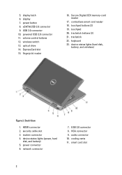
... status lights (power, hard disk, and battery) 5. power connector 6. VGA connector 9. audio connector 10. cooling vents 11. Back View 1. network connector 7. USB 3.0 connector 10. fingerprint reader 16. USB 2.0 connector 8. powered USB 3.0 connector 11. Secure Digital (SD) memory-card reader 17. keyboard 23. security cable slot 3. display 7. volume control buttons 12. smart card slot...
... status lights (power, hard disk, and battery) 5. power connector 6. VGA connector 9. audio connector 10. cooling vents 11. Back View 1. network connector 7. USB 3.0 connector 10. fingerprint reader 16. USB 2.0 connector 8. powered USB 3.0 connector 11. Secure Digital (SD) memory-card reader 17. keyboard 23. security cable slot 3. display 7. volume control buttons 12. smart card slot...
User Manual
Page 3
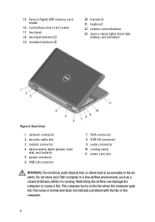
... environment, such as a closed briefcase, while it is normal and does not indicate a problem with the fan or the computer. Do not store your Dell computer in the air vents. display release latch 4. powered USB 3.0 connector 11. The computer turns on the fan when the computer gets hot. camera status light 6. eSATA...
... environment, such as a closed briefcase, while it is normal and does not indicate a problem with the fan or the computer. Do not store your Dell computer in the air vents. display release latch 4. powered USB 3.0 connector 11. The computer turns on the fan when the computer gets hot. camera status light 6. eSATA...
User Manual
Page 4
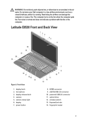
contactless smart card reader 17. touchpad 18. keyboard 22. device status lights (hard disk, battery, and wireless) Figure 4. USB 2.0 connector 7. USB 3.0 connector 9. smart card slot WARNING: Do not block, push objects into, or allow dust to accumulate in a low-airflow environment, such as a closed ...computer gets hot. trackstick buttons (3) 20. volume control buttons 23. security cable slot 3. network connector 2. 15. cooling vents 11. Do not store your Dell computer in the air vents. Restricting the airflow can damage the computer or cause a fire.
contactless smart card reader 17. touchpad 18. keyboard 22. device status lights (hard disk, battery, and wireless) Figure 4. USB 2.0 connector 7. USB 3.0 connector 9. smart card slot WARNING: Do not block, push objects into, or allow dust to accumulate in a low-airflow environment, such as a closed ...computer gets hot. trackstick buttons (3) 20. volume control buttons 23. security cable slot 3. network connector 2. 15. cooling vents 11. Do not store your Dell computer in the air vents. Restricting the airflow can damage the computer or cause a fire.
User Manual
Page 5
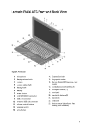
... 15. trackstick 22. camera status light 5. contactless smart card reader 18. touchpad 20. device status lights (hard disk, battery, and wireless) 5 Latitude E6430 ATG Front and Back View Figure 5. powered USB 3.0 connector 11. USB 3.0 connector 10. camera 4. display release latch 3. Secure Digital (SD) memory-card reader 17. Front view 1. wireless switch 13. keyboard 23.
... 15. trackstick 22. camera status light 5. contactless smart card reader 18. touchpad 20. device status lights (hard disk, battery, and wireless) 5 Latitude E6430 ATG Front and Back View Figure 5. powered USB 3.0 connector 11. USB 3.0 connector 10. camera 4. display release latch 3. Secure Digital (SD) memory-card reader 17. Front view 1. wireless switch 13. keyboard 23.
User Manual
Page 6
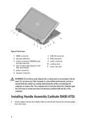
... to unlock and remove the covering plugs from their slots. 6 HDMI connector 2. through (optional) 4. USB 2.0 connector 8. security cable slot 3. power connector 6. audio connector 10. VGA connector 9. Back view 1. Do not store your Dell computer in the air vents. network connector 7. device status lights (power, hard disk, and battery) 5. Installing Handle Assembly (Latitude E6430 ATG) 1.
... to unlock and remove the covering plugs from their slots. 6 HDMI connector 2. through (optional) 4. USB 2.0 connector 8. security cable slot 3. power connector 6. audio connector 10. VGA connector 9. Back view 1. Do not store your Dell computer in the air vents. network connector 7. device status lights (power, hard disk, and battery) 5. Installing Handle Assembly (Latitude E6430 ATG) 1.
User Manual
Page 8
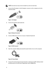
Figure 7. Network Connector 3. Connect the external antennae (purchased by customer) to the RF cable (provided by Dell) present on the computer and to the electrical outlet. Connect the AC adapter to turn on the computer. Connect the network cable (optional).... Open the computer display and press the power button to the AC adapter connector on the RF board. (Applicable only for E6430 ATG) 8 USB Connector 4. Power Button 5. Connect USB devices, such as a mouse or keyboard (optional). NOTE: Some devices may not be included if you did not order them. 1. ...
Figure 7. Network Connector 3. Connect the external antennae (purchased by customer) to the RF cable (provided by Dell) present on the computer and to the electrical outlet. Connect the AC adapter to turn on the computer. Connect the network cable (optional).... Open the computer display and press the power button to the AC adapter connector on the RF board. (Applicable only for E6430 ATG) 8 USB Connector 4. Power Button 5. Connect USB devices, such as a mouse or keyboard (optional). NOTE: Some devices may not be included if you did not order them. 1. ...
Owner's Manual
Page 62
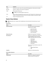
.... Moves to the previous page till you to configure the integrated network controller. Table 2. The options are selected. • Diskette Drive • Internal HDD • USB Storage Device • CD/DVD/CD-RW Drive • Onboard NIC You can also choose the Boot List option. Allows you to save any unsaved...
.... Moves to the previous page till you to configure the integrated network controller. Table 2. The options are selected. • Diskette Drive • Internal HDD • USB Storage Device • CD/DVD/CD-RW Drive • Onboard NIC You can also choose the Boot List option. Allows you to save any unsaved...

Owner's Manual
Page 64
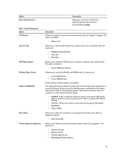
... keyboard illumination feature. The option is disabled by default. • Enable Stealth Mode Allows you to define the USB configuration. Option USB Configuration USB PowerShare Keyboard Illumination Stealth Mode Control Miscellaneous Devices 64 Description • Enable SMART Reporting - The options are: &#...8226; Disable Media Card Default Setting: All devices are enabled. The options are: • Enable Boot Support • Enable External USB Port Default Setting: both the options are enabled The option is disabled by default. The options are: • Disabled (Default ...
... keyboard illumination feature. The option is disabled by default. • Enable Stealth Mode Allows you to define the USB configuration. Option USB Configuration USB PowerShare Keyboard Illumination Stealth Mode Control Miscellaneous Devices 64 Description • Enable SMART Reporting - The options are: &#...8226; Disable Media Card Default Setting: All devices are enabled. The options are: • Enable Boot Support • Enable External USB Port Default Setting: both the options are enabled The option is disabled by default. The options are: • Disabled (Default ...
Owner's Manual
Page 67
... Allows you to block the computer from the off state when triggered by default. • Block Sleep (S3) Allows you to enable the USB devices to enable or disable the HyperThreading in the operating system. The options are: • Disabled (Default Setting) • Every Day •... wake-up from entering into the sleep state. Power Management Option AC Behavior Auto On Time USB Wake Support Wireless Radio Control Wake on automatically. The option is disabled • Enable USB Wake Support Allows you to wake the computer from the Standby state is disabled by a special ...
... Allows you to block the computer from the off state when triggered by default. • Block Sleep (S3) Allows you to enable the USB devices to enable or disable the HyperThreading in the operating system. The options are: • Disabled (Default Setting) • Every Day •... wake-up from entering into the sleep state. Power Management Option AC Behavior Auto On Time USB Wake Support Wireless Radio Control Wake on automatically. The option is disabled • Enable USB Wake Support Allows you to wake the computer from the Standby state is disabled by a special ...
Owner's Manual
Page 75
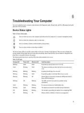
... Solid Blinking The display encountered a problem during the operation of the keyboard. Solid Blinking Solid The memory modules are installed/detected. Blinking Off Blinking The USB controller encountered a problem during initialization. The device status LEDs are used to indicate battery charge status.
... Solid Blinking The display encountered a problem during the operation of the keyboard. Solid Blinking Solid The memory modules are installed/detected. Blinking Off Blinking The USB controller encountered a problem during initialization. The device status LEDs are used to indicate battery charge status.
Owner's Manual
Page 78
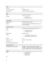
Audio Speakers Internal speaker amplifier Volume controls Video Type Controller Communications Network adapter Wireless Ports and Connectors Audio Video Network adapter USB 2.0 USB 3.0 Memory card reader Docking port Subscriber Identity Module (SIM) card Contactless Smart Card Supported Smart Cards/Technologies Display Type ...connector • one 15-pin VGA connector • 19-pin HDMI connector one RJ-45 connector • one 4-pin USB 2.0-compliant connector • one eSATA/USB 2.0-compliant connector two one 8-in-1 memory card reader one one ISO14443A - 106 kbps, 212 kbps, 424 kbps, and ...
Audio Speakers Internal speaker amplifier Volume controls Video Type Controller Communications Network adapter Wireless Ports and Connectors Audio Video Network adapter USB 2.0 USB 3.0 Memory card reader Docking port Subscriber Identity Module (SIM) card Contactless Smart Card Supported Smart Cards/Technologies Display Type ...connector • one 15-pin VGA connector • 19-pin HDMI connector one RJ-45 connector • one 4-pin USB 2.0-compliant connector • one eSATA/USB 2.0-compliant connector two one 8-in-1 memory card reader one one ISO14443A - 106 kbps, 212 kbps, 424 kbps, and ...
Intel Responsiveness Technologies Guide
Page 11
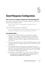
...pdf Pre-Installation Notes • If the system is in AHCI or ATA mode, Smart Response cannot be available for download from http://support.dell.com/ • Smart Response and Rapid Start can co-exist on some systems. • This section is designed to walk you through ...of Smart Response and Rapid Start is required for use with Smart Response? 5 Smart Response Configuration How to commonly experienced issues with USB-connected external drives. • The Intel Rapid Storage Technology driver and application package is significant. Smart Response Configuration 11
...pdf Pre-Installation Notes • If the system is in AHCI or ATA mode, Smart Response cannot be available for download from http://support.dell.com/ • Smart Response and Rapid Start can co-exist on some systems. • This section is designed to walk you through ...of Smart Response and Rapid Start is required for use with Smart Response? 5 Smart Response Configuration How to commonly experienced issues with USB-connected external drives. • The Intel Rapid Storage Technology driver and application package is significant. Smart Response Configuration 11
Latitude E-Family Re-Imaging Guide
Page 5
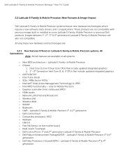
... are not compatible with previous images built or installed on all systems o New BIOS architecture - Latitude E-Family & Mobile Precision 1st & 2nd generation o Dell Control Vault o Contactless smartcard / RFID o Webcam o USB 3.0 o Free Fall Sensor on the mother board o Multi-touch Touchpad o Dell Control Point, 1st and 2nd generation Latitude E-Family & Mobile Precision o Dell Feature Enhancement Package(DFEP) -
... are not compatible with previous images built or installed on all systems o New BIOS architecture - Latitude E-Family & Mobile Precision 1st & 2nd generation o Dell Control Vault o Contactless smartcard / RFID o Webcam o USB 3.0 o Free Fall Sensor on the mother board o Multi-touch Touchpad o Dell Control Point, 1st and 2nd generation Latitude E-Family & Mobile Precision o Dell Feature Enhancement Package(DFEP) -
Latitude E-Family Re-Imaging Guide
Page 10
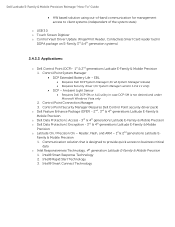
..., Flash, and ARM - 1st & 2nd generations Latitude EFamily & Mobile Precision 1. Intel® Smart Response Technology 2. Intel® Smart Connect Technology EBL Requires Dell DCP System Manager (for all System Manager release) Requires Security driver (for management access to client systems (independent of the system state) o USB 3.0 o Touch Screen Digitizer o Control Vault...
..., Flash, and ARM - 1st & 2nd generations Latitude EFamily & Mobile Precision 1. Intel® Smart Response Technology 2. Intel® Smart Connect Technology EBL Requires Dell DCP System Manager (for all System Manager release) Requires Security driver (for management access to client systems (independent of the system state) o USB 3.0 o Touch Screen Digitizer o Control Vault...
Latitude E-Family Re-Imaging Guide
Page 28
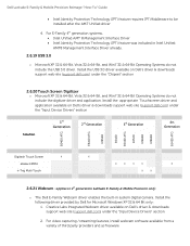
...and application available on Dell's driver & downloads support web site (support.dell.com) under the "Input Device Drivers" section Solution 1st Generation 2nd Generation 3rd Generation 4th Generation E6400 ATG E6410 ATG M6500 E6420 E6420 ATG E6520 M4600 M6600 E6430 ATG Digitech Touch Screen... Operating Systems do not include the USB 3.0 driver. For E-Family 4th generation systems, Intel Unified AMT 8 Management Interface Driver Intel Identity Protection Technology (IPT) feature was included in system digital camera. Dell Latitude E-Family & Mobile Precision Reimage ...
...and application available on Dell's driver & downloads support web site (support.dell.com) under the "Input Device Drivers" section Solution 1st Generation 2nd Generation 3rd Generation 4th Generation E6400 ATG E6410 ATG M6500 E6420 E6420 ATG E6520 M4600 M6600 E6430 ATG Digitech Touch Screen... Operating Systems do not include the USB 3.0 driver. For E-Family 4th generation systems, Intel Unified AMT 8 Management Interface Driver Intel Identity Protection Technology (IPT) feature was included in system digital camera. Dell Latitude E-Family & Mobile Precision Reimage ...

Latitude E-Family Re-Imaging Guide
Page 40
... this utility first after re-imaging your system. It can use the scheduling option to keep their system up to six times faster than USB 2.0 and IEEE 1394 o Robust and user friendly external connection o High performance, cost effective expansion storage o Up to 2 meter shielded cables...update preferences and apply updates based on the criticality. A few of the key benefits of the connectors on the Dell Drivers and Download page 7. What is primarily targeted at Customers who want to specify their own. Dell Latitude E-Family & Mobile Precision Reimage "How-To" Guide a.
... this utility first after re-imaging your system. It can use the scheduling option to keep their system up to six times faster than USB 2.0 and IEEE 1394 o Robust and user friendly external connection o High performance, cost effective expansion storage o Up to 2 meter shielded cables...update preferences and apply updates based on the criticality. A few of the key benefits of the connectors on the Dell Drivers and Download page 7. What is primarily targeted at Customers who want to specify their own. Dell Latitude E-Family & Mobile Precision Reimage "How-To" Guide a.

Latitude E-Family Re-Imaging Guide
Page 44
... no longer require a docking profile Note: USB devices might be malfunction after docking/undocking. Please refer to http://support.microsoft.com/kb/871233 to get workaround. Dell Latitude E-Family & Mobile Precision Reimage "How-To" Guide Appendix E E-Docks - Dell E-Docks (E-Family Docking Stations) o Dell E-Family docking stations are the list of Dell docking stations. It's a known issue...
... no longer require a docking profile Note: USB devices might be malfunction after docking/undocking. Please refer to http://support.microsoft.com/kb/871233 to get workaround. Dell Latitude E-Family & Mobile Precision Reimage "How-To" Guide Appendix E E-Docks - Dell E-Docks (E-Family Docking Stations) o Dell E-Family docking stations are the list of Dell docking stations. It's a known issue...


