Service Manual
Page 11
... problem encountered during a test, a message appears with an error code and a description of the problem. Configuration Displays the hardware configuration for your part. If you select Extended Test to be run from System Setup, memory, and various internal tests, and displays the information in the device list ...typically can take 10 to complete. NOTE: The Express Test requires no interaction on the screen. The Service Tag for the selected device. Dell™ Latitude™ E6400 XFR Service Manual thirty minutes or more thorough check of devices in the computer.
... problem encountered during a test, a message appears with an error code and a description of the problem. Configuration Displays the hardware configuration for your part. If you select Extended Test to be run from System Setup, memory, and various internal tests, and displays the information in the device list ...typically can take 10 to complete. NOTE: The Express Test requires no interaction on the screen. The Service Tag for the selected device. Dell™ Latitude™ E6400 XFR Service Manual thirty minutes or more thorough check of devices in the computer.
Service Manual
Page 12
..., follow the safety instructions that shipped with your computer: If you added or removed a part before the problem started, review the installation procedures and ensure that the part is correctly installed. If a peripheral device does not work, ensure that the device is...you want to use . Insert a bootable floppy disk, CD, or DVD. In some cases, you may have to remove. 3. Dell™ Latitude™ E6400 XFR Service Manual 1.1.4 Error Messages CAUTION: Before you begin any of the procedures in this section, follow the safety instructions that shipped with ...
..., follow the safety instructions that shipped with your computer: If you added or removed a part before the problem started, review the installation procedures and ensure that the part is correctly installed. If a peripheral device does not work, ensure that the device is...you want to use . Insert a bootable floppy disk, CD, or DVD. In some cases, you may have to remove. 3. Dell™ Latitude™ E6400 XFR Service Manual 1.1.4 Error Messages CAUTION: Before you begin any of the procedures in this section, follow the safety instructions that shipped with ...
Service Manual
Page 17
.... Use this section, follow the safety instructions that shipped with a PCI graphics card installed, removal of your computer. Dell™ Latitude™ E6400 XFR Service Manual ELIMINATE POSSIBLE INTERFERENCE - Click or double-click the speaker icon in the lower-right corner of the card ...support.dell.com. CHECK THE DIAGNOSTIC LIGHTS - See the Dell™ Technology Guide on the computer and the monitor and adjust the monitor brightness and contrast controls. Windows XP: 1. Click Start→ Control Panel→ Appearance and Themes. 2. Windows Vista: 1. Only Part of...
.... Use this section, follow the safety instructions that shipped with a PCI graphics card installed, removal of your computer. Dell™ Latitude™ E6400 XFR Service Manual ELIMINATE POSSIBLE INTERFERENCE - Click or double-click the speaker icon in the lower-right corner of the card ...support.dell.com. CHECK THE DIAGNOSTIC LIGHTS - See the Dell™ Technology Guide on the computer and the monitor and adjust the monitor brightness and contrast controls. Windows XP: 1. Click Start→ Control Panel→ Appearance and Themes. 2. Windows Vista: 1. Only Part of...
Service Manual
Page 48
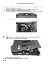
... release the snaps, lift the LCD edge, of the base assembly. NOTE: The handle will fall off when the palm rest is removed. Dell™ Latitude™ E6400 XFR Service Manual 6. Lift the touch pad cable to reveal the contactless smart card cable underneath. Remove the one M2.5 x 5-mm screw on the... bottom of the palm rest. NOTE: There are four snap hooks located in front of the mouse touchpad as part of the palm ...
... release the snaps, lift the LCD edge, of the base assembly. NOTE: The handle will fall off when the palm rest is removed. Dell™ Latitude™ E6400 XFR Service Manual 6. Lift the touch pad cable to reveal the contactless smart card cable underneath. Remove the one M2.5 x 5-mm screw on the... bottom of the palm rest. NOTE: There are four snap hooks located in front of the mouse touchpad as part of the palm ...

Service Manual
Page 66
... procedures in Before Working on Your Computer. 37 Doors 37.1 Removing Media Bay Door Parts Location 1 2 1 Media bay door 2 M3 x 3 mm screws (3) CAUTION: Before you begin any of the base assembly 37.2 Replacing Media Bay Door 1. Dell™ Latitude™ E6400 XFR Service Manual NOTICE: Image above has palm rest removed to relieve hinge pressure...
... procedures in Before Working on Your Computer. 37 Doors 37.1 Removing Media Bay Door Parts Location 1 2 1 Media bay door 2 M3 x 3 mm screws (3) CAUTION: Before you begin any of the base assembly 37.2 Replacing Media Bay Door 1. Dell™ Latitude™ E6400 XFR Service Manual NOTICE: Image above has palm rest removed to relieve hinge pressure...

Service Manual
Page 67
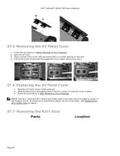
... on Your Computer. 37.3 Removing the AV Door Parts Location 1 2 1 Door 2 M3 x 3 mm (2) 1. Follow the procedures in After Working on Your Computer. 2. Insert door hinge onto assembly and align the hinge divots. 2. Open the door to relieve hinge pressure. 3. Page 67 Dell™ Latitude™ E6400 XFR Service Manual 2. Insert the three M3 x 3-mm screws...
... on Your Computer. 37.3 Removing the AV Door Parts Location 1 2 1 Door 2 M3 x 3 mm (2) 1. Follow the procedures in After Working on Your Computer. 2. Insert door hinge onto assembly and align the hinge divots. 2. Open the door to relieve hinge pressure. 3. Page 67 Dell™ Latitude™ E6400 XFR Service Manual 2. Insert the three M3 x 3-mm screws...
Service Manual
Page 68
Dell™ Latitude™ E6400 XFR Service Manual 37.5 Removing the AV Panel Cover 1. Follow the procedures in the lower USB slot where there is advised to check these options as soon as possible. See Replacing the Wi-Fi Sniffer Card for details. 37.7 Removing the RJ11 Door Parts Location Page 68 Place a scribe in Before...
Dell™ Latitude™ E6400 XFR Service Manual 37.5 Removing the AV Panel Cover 1. Follow the procedures in the lower USB slot where there is advised to check these options as soon as possible. See Replacing the Wi-Fi Sniffer Card for details. 37.7 Removing the RJ11 Door Parts Location Page 68 Place a scribe in Before...
Service Manual
Page 70
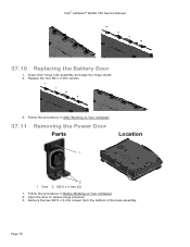
Replace the four M3 x 3-mm screws. 3. Follow the procedures in After Working on Your Computer. 2. Follow the procedures in Before Working on Your Computer. 37.11 Removing the Power Door Parts Location 1 2 1 Door 2 M2.5 x 5-mm (2) 1. Remove the two M2.5 x 5-mm screws from the bottom of the base assembly Page 70 Open the door to relieve hinge pressure. 3. Dell™ Latitude™ E6400 XFR Service Manual 37.10 Replacing the Battery Door 1. Insert door hinge onto assembly and align the hinge divots. 2.
Replace the four M3 x 3-mm screws. 3. Follow the procedures in After Working on Your Computer. 2. Follow the procedures in Before Working on Your Computer. 37.11 Removing the Power Door Parts Location 1 2 1 Door 2 M2.5 x 5-mm (2) 1. Remove the two M2.5 x 5-mm screws from the bottom of the base assembly Page 70 Open the door to relieve hinge pressure. 3. Dell™ Latitude™ E6400 XFR Service Manual 37.10 Replacing the Battery Door 1. Insert door hinge onto assembly and align the hinge divots. 2.
Service Manual
Page 71
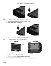
Dell™ Latitude™ E6400 XFR Service Manual 37.12 Replacing the Power Door 1. Follow the procedures in Before Working on Your Computer. 37.13 Removing the VGA Door Parts Location 1 2 1 Door 2 M3 x 3 mm (2) 1. Follow the procedures in After Working on Your Computer. 2. Page 71 Open the door to relieve hinge pressure. 3. Replace the two M2.5 x 5-mm screws. 3. Remove the two M3 x 3-mm screws from the bottom of the base assembly. Insert door hinge onto assembly and align the hinge divots. 2.
Dell™ Latitude™ E6400 XFR Service Manual 37.12 Replacing the Power Door 1. Follow the procedures in Before Working on Your Computer. 37.13 Removing the VGA Door Parts Location 1 2 1 Door 2 M3 x 3 mm (2) 1. Follow the procedures in After Working on Your Computer. 2. Page 71 Open the door to relieve hinge pressure. 3. Replace the two M2.5 x 5-mm screws. 3. Remove the two M3 x 3-mm screws from the bottom of the base assembly. Insert door hinge onto assembly and align the hinge divots. 2.

Service Manual
Page 72
Dell™ Latitude™ E6400 XFR Service Manual 37.14 Replacing the VGA Door 1. Replace the two VGA connector socket screws. 3. Replace the two M3 x 3-mm screws. 3. Follow the procedures in After Working on Your Computer. 37.17 Removing the HDD Door Parts Location Page 72 Follow the procedures in After Working on Your Computer. Removing...
Dell™ Latitude™ E6400 XFR Service Manual 37.14 Replacing the VGA Door 1. Replace the two VGA connector socket screws. 3. Replace the two M3 x 3-mm screws. 3. Follow the procedures in After Working on Your Computer. 37.17 Removing the HDD Door Parts Location Page 72 Follow the procedures in After Working on Your Computer. Removing...

Service Manual
Page 73
Insert door hinge onto assembly and align the hinge divots. 2. Follow the procedures in Before Working on Your Computer. 37.19 Removing the SD Card Door Parts Location Page 73 Open the door to relieve hinge pressure. 3. Remove the two M3 x 3-mm screws from the bottom of the base assembly 37.18 Replacing the HDD Door 1. Replace the two M3 x 3-mm screws. 3. Follow the procedures in After Working on Your Computer. 2. Dell™ Latitude™ E6400 XFR Service Manual 1 2 1 Door 2 M3 x3 mm (2) 1.
Insert door hinge onto assembly and align the hinge divots. 2. Follow the procedures in Before Working on Your Computer. 37.19 Removing the SD Card Door Parts Location Page 73 Open the door to relieve hinge pressure. 3. Remove the two M3 x 3-mm screws from the bottom of the base assembly 37.18 Replacing the HDD Door 1. Replace the two M3 x 3-mm screws. 3. Follow the procedures in After Working on Your Computer. 2. Dell™ Latitude™ E6400 XFR Service Manual 1 2 1 Door 2 M3 x3 mm (2) 1.


