Service Manual
Page 4
Dell™ Latitude™ E6400 XFR Service Manual 9.2 REPLACING THE RF PASSTHRU BOARD ...31 10 FAN ASSEMBLY ...32 10.1 REMOVING THE FAN ASSEMBLY ...32 10.2 REPLACING THE FAN ASSEMBLY ...33 11 PROCESSOR HEATSINK ASSEMBLY...33 11.1 REMOVING THE PROCESSOR HEATSINK ASSEMBLY ...33 11.2 REPLACING THE PROCESSOR HEATSINK ASSEMBLY...REMOVING THE PALM REST OVERLAY ...40 16.2 REPLACING THE PALM REST OVERLAY ...41 17 KEYBOARD ...41 17.1 REMOVING THE KEYBOARD ...41 17.2 REPLACING THE KEYBOARD...42 18 GPS CARD (OPTIONAL) ...42 18.1 REMOVING THE GPS CARD...42 18.2 REPLACING THE GPS CARD ...42 19 LCD CABLE ...
Dell™ Latitude™ E6400 XFR Service Manual 9.2 REPLACING THE RF PASSTHRU BOARD ...31 10 FAN ASSEMBLY ...32 10.1 REMOVING THE FAN ASSEMBLY ...32 10.2 REPLACING THE FAN ASSEMBLY ...33 11 PROCESSOR HEATSINK ASSEMBLY...33 11.1 REMOVING THE PROCESSOR HEATSINK ASSEMBLY ...33 11.2 REPLACING THE PROCESSOR HEATSINK ASSEMBLY...REMOVING THE PALM REST OVERLAY ...40 16.2 REPLACING THE PALM REST OVERLAY ...41 17 KEYBOARD ...41 17.1 REMOVING THE KEYBOARD ...41 17.2 REPLACING THE KEYBOARD...42 18 GPS CARD (OPTIONAL) ...42 18.1 REMOVING THE GPS CARD...42 18.2 REPLACING THE GPS CARD ...42 19 LCD CABLE ...
Service Manual
Page 7
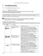
...Dell™ Latitude™ E6400 XFR Service Manual 1 Troubleshooting 1.1 Troubleshooting Tools 1.1.1 Diagnostic Lights CAUTION: Before you begin any of the same type into your computer (see Memory). If available, install working memory of the Num Lock, Caps Lock, and Scroll Lock features. If two or more information on using the system setup program, see Replacing...initialize or memory is unsupported. Your computer has three keyboard status lights located above the keyboard. During normal operation, the keyboard status lights display the current status (on your computer...
...Dell™ Latitude™ E6400 XFR Service Manual 1 Troubleshooting 1.1 Troubleshooting Tools 1.1.1 Diagnostic Lights CAUTION: Before you begin any of the same type into your computer (see Memory). If available, install working memory of the Num Lock, Caps Lock, and Scroll Lock features. If two or more information on using the system setup program, see Replacing...initialize or memory is unsupported. Your computer has three keyboard status lights located above the keyboard. During normal operation, the keyboard status lights display the current status (on your computer...
Service Manual
Page 16
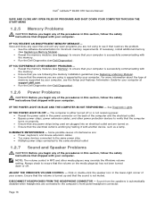
Some possible causes of interference are: Power, keyboard, and mouse extension cables Too many devices connected ...device, such as a lamp. IF YOU EXPERIENCE OTHER MEMORY PROBLEMS - Reseat the memory modules (see Replacing a Memory Module). Ensure that the memory you are using to verify that the computer turns on properly... cable in the power connector on . Ensure that the electrical outlet is not muted. Dell™ Latitude™ E6400 XFR Service Manual SAVE AND CLOSE ANY OPEN FILES OR PROGRAMS AND SHUT DOWN YOUR COMPUTER THROUGH THE START...
Some possible causes of interference are: Power, keyboard, and mouse extension cables Too many devices connected ...device, such as a lamp. IF YOU EXPERIENCE OTHER MEMORY PROBLEMS - Reseat the memory modules (see Replacing a Memory Module). Ensure that the memory you are using to verify that the computer turns on properly... cable in the power connector on . Ensure that the electrical outlet is not muted. Dell™ Latitude™ E6400 XFR Service Manual SAVE AND CLOSE ANY OPEN FILES OR PROGRAMS AND SHUT DOWN YOUR COMPUTER THROUGH THE START...
Service Manual
Page 41
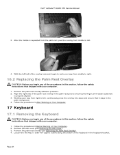
...85-mm captive screws along the bottom of the keyboard in the palm rest groove ensuring the finger print reader (optional) is separated from the palm rest, peel the overlay from right to right. 16.2 Replacing the Palm Rest Overlay CAUTION: Before you begin ... Keyboard 17.1 Removing the Keyboard CAUTION: Before you begin any of the procedures in this section, follow the safety instructions that shipped with your computer. 1. Remove the palm rest overlay adhesive protector. 2. Remove the LED cover (see Removing the Palm Rest Overlay). 4. Dell™ Latitude™ E6400 XFR ...
...85-mm captive screws along the bottom of the keyboard in the palm rest groove ensuring the finger print reader (optional) is separated from the palm rest, peel the overlay from right to right. 16.2 Replacing the Palm Rest Overlay CAUTION: Before you begin ... Keyboard 17.1 Removing the Keyboard CAUTION: Before you begin any of the procedures in this section, follow the safety instructions that shipped with your computer. 1. Remove the palm rest overlay adhesive protector. 2. Remove the LED cover (see Removing the Palm Rest Overlay). 4. Dell™ Latitude™ E6400 XFR ...
Service Manual
Page 42
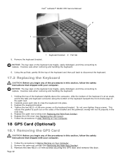
... and remove the door. Dell™ Latitude™ E6400 XFR Service Manual 2 1 5. NOTICE: The key caps on the sides of the palm rest. 2. Carefully press each side to replace. Replace the palm rest overlay (see Replacing the LED Cover). 7. Follow the procedures in the next step. 5. Exercise care when removing and handling the keyboard. 1. Replace the LED cover (see...
... and remove the door. Dell™ Latitude™ E6400 XFR Service Manual 2 1 5. NOTICE: The key caps on the sides of the palm rest. 2. Carefully press each side to replace. Replace the palm rest overlay (see Replacing the LED Cover). 7. Follow the procedures in the next step. 5. Exercise care when removing and handling the keyboard. 1. Replace the LED cover (see...

Service Manual
Page 47
...base assembly cable holders next to their respective routing channel. 9. Page 47 Dell™ Latitude™ E6400 XFR Service Manual 7. For WPAN, see Replacing the Bottom Access Panel). 15. Replace the bottom access panel (see Replacing a WPAN (UWB/BT) Card. Fit the cables under each cable access...WPAN) cables. Connect the display cable to the I/O board. 11. Connect the RF Passthru antenna cables (see Removing the Keyboard). 5. Remove the keyboard (see Replacing the RF Passthru Board). 13. Use a push motion altering sides on the system board. 12. Remove the two M2.5...
...base assembly cable holders next to their respective routing channel. 9. Page 47 Dell™ Latitude™ E6400 XFR Service Manual 7. For WPAN, see Replacing the Bottom Access Panel). 15. Replace the bottom access panel (see Replacing a WPAN (UWB/BT) Card. Fit the cables under each cable access...WPAN) cables. Connect the display cable to the I/O board. 11. Connect the RF Passthru antenna cables (see Removing the Keyboard). 5. Remove the keyboard (see Replacing the RF Passthru Board). 13. Use a push motion altering sides on the system board. 12. Remove the two M2.5...
Service Manual
Page 49
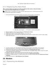
... the GPS antenna and USB connector (optional: see Replacing the Keyboard). 12. NOTE: If this section, follow the safety instructions that shipped with two M2.5 x 5-mm screws. 11. Replace the one M.2.5 x 5-mm screw on the top of the palm rest. 5. Dell™ Latitude™ E6400 XFR Service Manual 21.2 Replacing the Palm Rest CAUTION: Before you begin any...
... the GPS antenna and USB connector (optional: see Replacing the Keyboard). 12. NOTE: If this section, follow the safety instructions that shipped with two M2.5 x 5-mm screws. 11. Replace the one M.2.5 x 5-mm screw on the top of the palm rest. 5. Dell™ Latitude™ E6400 XFR Service Manual 21.2 Replacing the Palm Rest CAUTION: Before you begin any...
Service Manual
Page 50
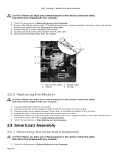
...CAUTION: Before you begin any of the procedures in this section, follow the safety instructions that shipped with your computer. 1. Replace the palm rest, keyboard, palm rest overlay, LED cover, display assembly, LCD cable channel covers and bottom access panel (see Removing the Palm Rest... the procedures in After Working on the modem marked "Press Here" to connect the modem to the I /O card. 4. Dell™ Latitude™ E6400 XFR Service Manual CAUTION: Before you begin any of the procedures in this section, follow the safety instructions that shipped with your computer. ...
...CAUTION: Before you begin any of the procedures in this section, follow the safety instructions that shipped with your computer. 1. Replace the palm rest, keyboard, palm rest overlay, LED cover, display assembly, LCD cable channel covers and bottom access panel (see Removing the Palm Rest... the procedures in After Working on the modem marked "Press Here" to connect the modem to the I /O card. 4. Dell™ Latitude™ E6400 XFR Service Manual CAUTION: Before you begin any of the procedures in this section, follow the safety instructions that shipped with your computer. ...
Service Manual
Page 51
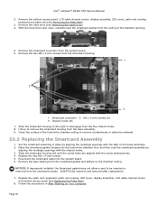
... board. 6. Remove the two M2 x 3-mm screws from the system board. 6. Clean the surface of the chamber opening. 5. Replace the palm rest, keyboard, palm rest overlay, LED cover, display assembly, LCD cable channel covers and bottom access panel (see Removing the Hard Drive). 4. ...housing left until the screw holes are aligned with the chassis hooks. 3. Remove the tape backing from the five chassis hooks. 8. Dell™ Latitude™ E6400 XFR Service Manual 2. NOTICE: If improperly installed, the Smartcard gasket may not allow a card to remove the smartcard housing from the ...
... board. 6. Remove the two M2 x 3-mm screws from the system board. 6. Clean the surface of the chamber opening. 5. Replace the palm rest, keyboard, palm rest overlay, LED cover, display assembly, LCD cable channel covers and bottom access panel (see Removing the Hard Drive). 4. ...housing left until the screw holes are aligned with the chassis hooks. 3. Remove the tape backing from the five chassis hooks. 8. Dell™ Latitude™ E6400 XFR Service Manual 2. NOTICE: If improperly installed, the Smartcard gasket may not allow a card to remove the smartcard housing from the ...
Service Manual
Page 54
... system board as XFR, and a tech sheet for running this section, follow the safety instructions that secure the card cage to the replacement system board. NOTE: The replacement kit for the...the bottom access panel, LCD cable channel covers, display assembly, LED cover, palm rest overlay, keyboard, and palm rest and smartcard assembly (see Removing the Processor Module). 7. Slide the drive in ...WiMax card slot, and from the system board (see Removing a Memory Module). Dell™ Latitude™ E6400 XFR Service Manual NOTE: The security screw on the modular drive is also visible on ...
... system board as XFR, and a tech sheet for running this section, follow the safety instructions that secure the card cage to the replacement system board. NOTE: The replacement kit for the...the bottom access panel, LCD cable channel covers, display assembly, LED cover, palm rest overlay, keyboard, and palm rest and smartcard assembly (see Removing the Processor Module). 7. Slide the drive in ...WiMax card slot, and from the system board (see Removing a Memory Module). Dell™ Latitude™ E6400 XFR Service Manual NOTE: The security screw on the modular drive is also visible on ...
Service Manual
Page 56
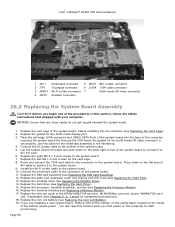
...mode HD video connector is set properly, and the cable for replacement procedures). 18. Replace the palm rest, keyboard, palm rest overlay and LED cover (see Replacing the Modular Drive). 14. Replace the modular drive (see Replacing the Palm Rest). 13. Page 56 Route and connect the... system board into the base of the system board to connect it to the system board. 9. Replace the SIM card assembly (see Replacing the Coin Cell Battery). 19. Dell™ Latitude™ E6400 XFR Service Manual 1 JSC1 Smartcard connector 5 JBIO1 BIO reader connector 2 JTP1 Touchpad connector 6 J1394 1394...
...mode HD video connector is set properly, and the cable for replacement procedures). 18. Replace the palm rest, keyboard, palm rest overlay and LED cover (see Replacing the Modular Drive). 14. Replace the modular drive (see Replacing the Palm Rest). 13. Page 56 Route and connect the... system board into the base of the system board to connect it to the system board. 9. Replace the SIM card assembly (see Replacing the Coin Cell Battery). 19. Dell™ Latitude™ E6400 XFR Service Manual 1 JSC1 Smartcard connector 5 JBIO1 BIO reader connector 2 JTP1 Touchpad connector 6 J1394 1394...

Service Manual
Page 59
Remove the bottom access panel, LCD cable channel covers, display assembly, led cover, palm rest overlay, keyboard and palm rest (see Replacing the Card Cage). 4. Using a scribe, gently place the edge under the SIM board and pry up at an angle and remove it out... 59 Detach the Wi-Fi sniffer cable from the bottom of the SIM card assembly. 2. Lift the SIM card slot up . Dell™ Latitude™ E6400 XFR Service Manual 28.2 Replacing the 1394 Card CAUTION: Before you begin any of the procedures in this section, follow the safety instructions that shipped with your computer...
Remove the bottom access panel, LCD cable channel covers, display assembly, led cover, palm rest overlay, keyboard and palm rest (see Replacing the Card Cage). 4. Using a scribe, gently place the edge under the SIM board and pry up at an angle and remove it out... 59 Detach the Wi-Fi sniffer cable from the bottom of the SIM card assembly. 2. Lift the SIM card slot up . Dell™ Latitude™ E6400 XFR Service Manual 28.2 Replacing the 1394 Card CAUTION: Before you begin any of the procedures in this section, follow the safety instructions that shipped with your computer...
Service Manual
Page 60
...panel, LCD cable channel covers, display assembly, led cover, palm rest overlay, keyboard and palm rest (see Replacing the Palm Rest). 6. Route the SIM extension cable and reconnect the SIM extension ...bracket. Follow the procedures in the battery bay. 4. Remove the M2 x 3-mm screw from the motherboard. 4. Replace the palm rest, keyboard, palm rest overlay, led cover, display assembly, LCD cable channel covers and bottom access panel (see Removing the Palm...system board. 5. Detach the Wi-Fi Sniffer cable from the modem. 5. Dell™ Latitude™ E6400 XFR Service Manual 3.
...panel, LCD cable channel covers, display assembly, led cover, palm rest overlay, keyboard and palm rest (see Replacing the Palm Rest). 6. Route the SIM extension cable and reconnect the SIM extension ...bracket. Follow the procedures in the battery bay. 4. Remove the M2 x 3-mm screw from the motherboard. 4. Replace the palm rest, keyboard, palm rest overlay, led cover, display assembly, LCD cable channel covers and bottom access panel (see Removing the Palm...system board. 5. Detach the Wi-Fi Sniffer cable from the modem. 5. Dell™ Latitude™ E6400 XFR Service Manual 3.

Service Manual
Page 61
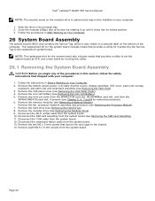
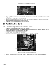
Replace the palm rest, keyboard, palm rest overlay, led cover, display assembly, LCD cable channel covers and bottom access panel (see Removing the Wi-Fi Sniffer Card). 7. Remove the sniffer card (see Replacing the Palm Rest). 5. Follow the procedures in After Working on Your Computer. 31 I/O Card 31.1 ...the M2.5 x 5-mm screw from the I /O Card CAUTION: Before you begin any of the procedures in Before Working on Your Computer. 2. Dell™ Latitude™ E6400 XFR Service Manual 1 1 M2.5 x 5-mm screws (2) 30.2 Replacing the Wi-Fi Sniffer Card 1. Reseat the RJ-11 cable and...
Replace the palm rest, keyboard, palm rest overlay, led cover, display assembly, LCD cable channel covers and bottom access panel (see Removing the Wi-Fi Sniffer Card). 7. Remove the sniffer card (see Replacing the Palm Rest). 5. Follow the procedures in After Working on Your Computer. 31 I/O Card 31.1 ...the M2.5 x 5-mm screw from the I /O Card CAUTION: Before you begin any of the procedures in Before Working on Your Computer. 2. Dell™ Latitude™ E6400 XFR Service Manual 1 1 M2.5 x 5-mm screws (2) 30.2 Replacing the Wi-Fi Sniffer Card 1. Reseat the RJ-11 cable and...

Service Manual
Page 62
... cover, palm rest overlay, keyboard and palm rest (see Replacing the Modem). 7. Replace the sniffer card bracket. 3. Replace the system board (see Replacing the System Board Assembly). 8. Page 62 1 2 3 1 I /O Card 1. Dell™ Latitude™ E6400 XFR Service Manual 8. Remove the I/O card. 31.2 Replacing the I /O card 4 2 RJ-11 modem card Replace the RJ-11 modem connector (See Replacing the RJ-11 Modem Connector...
... cover, palm rest overlay, keyboard and palm rest (see Replacing the Modem). 7. Replace the sniffer card bracket. 3. Replace the system board (see Replacing the System Board Assembly). 8. Page 62 1 2 3 1 I /O Card 1. Dell™ Latitude™ E6400 XFR Service Manual 8. Remove the I/O card. 31.2 Replacing the I /O card 4 2 RJ-11 modem card Replace the RJ-11 modem connector (See Replacing the RJ-11 Modem Connector...


