Dell Latitude E6400 XFR Support Question
Dell Latitude E6400 XFR Support Question
Find answers below for this question about Dell Latitude E6400 XFR.Need a Dell Latitude E6400 XFR manual? We have 9 online manuals for this item!
Question posted by 13gchan on January 19th, 2014
How To Replace Power Jack On Dell Laptop E6400 Xfr Youtube
The person who posted this question about this Dell product did not include a detailed explanation. Please use the "Request More Information" button to the right if more details would help you to answer this question.
Current Answers
Related Dell Latitude E6400 XFR Manual Pages
Service Manual - Page 3
Dell™ Latitude™ E6400 XFR Service Manual
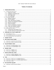
Table of Contents
1 TROUBLESHOOTING...7
1.1 TROUBLESHOOTING TOOLS ...7 1.1.1 Diagnostic Lights...7 1.1.2 Hardware Troubleshooter ...8 1.1.3 Dell... 5.2 REPLACING THE WLAN/WIMAX CARD ...25
6 WWAN CARD ...26
6.1 REMOVING A WWAN CARD ...26 6.2 REPLACING A WWAN CARD ...26
7 WPAN (UWB/BT) CARD...27
7.1 REMOVING A WPAN (UWB/BT) CARD ...27 7.2 REPLACING A...
Service Manual - Page 4
Dell™ Latitude™ E6400 XFR Service Manual
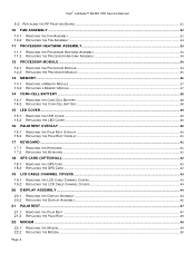
9.2 REPLACING THE RF PASSTHRU BOARD ...31
10 FAN ASSEMBLY ...32
10.1 REMOVING THE FAN ASSEMBLY ...32 10.2 REPLACING THE FAN ASSEMBLY ...33
11 PROCESSOR HEATSINK ASSEMBLY...33
11.1 REMOVING THE PROCESSOR HEATSINK ASSEMBLY ...33 11.2 REPLACING THE PROCESSOR HEATSINK ASSEMBLY ...34
12 PROCESSOR MODULE ...34
12.1 REMOVING THE PROCESSOR MODULE...
Service Manual - Page 5
Dell™ Latitude™ E6400 XFR Service Manual
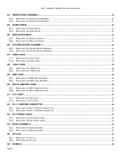
23 SMARTCARD ASSEMBLY ...50
23.1 REMOVING THE SMARTCARD ASSEMBLY ...50 23.2 REPLACING THE SMARTCARD ASSEMBLY ...51
24 HARD DRIVE...52
24.1 REMOVING THE HARD DRIVE...52 24.2 REPLACING THE HARD DRIVE ...53
25 MODULAR DRIVE...53
25.1 REMOVING THE MODULAR DRIVE...53 25.2 REPLACING THE MODULAR DRIVE ...53
26 SYSTEM...
Service Manual - Page 6
Dell™ Latitude™ E6400 XFR Service Manual
36.1 REMOVING THE HANDLE...65 36.2 REPLACING THE HANDLE ...65 37 DOORS ...66 37.1 REMOVING MEDIA BAY DOOR ...66 37.2 REPLACING MEDIA BAY DOOR...66 37.3 REMOVING THE AV DOOR...67 37.4 REPLACING THE AV DOOR ...67 37.5 REMOVING THE AV PANEL COVER ...68 37.6 REPLACING THE AV PANEL COVER...68...
Service Manual - Page 7
... the system setup program, see Replacing a Memory Module) and restart the computer. If the problem persists, contact Dell Support. If the
computer starts without error. If the computer starts normally, continue to install additional memory modules (one module (see the Dell™ Technology Guide on your computer. Dell™ Latitude™ E6400 XFR Service Manual
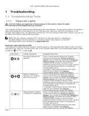
1 Troubleshooting...
Service Manual - Page 13
... that are checked. For information about setting power options, see the Dell™ Technology Guide on power management modes. Replace the battery only with your screen. ...right corner of your antivirus software to an optical drive
CLOSE OTHER PROGRAMS -
Dell™ Latitude™ E6400 XFR Service Manual
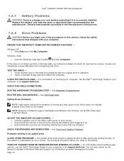
1.2.1 Battery Problems
CAUTION: There is a danger of a new battery...
Service Manual - Page 14
Dell™ Latitude™ E6400 XFR Service Manual
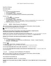
Hard Drive Problems
RUN CHECK DISK - Right-click Local Disk C:. 3. If ...Click Properties→ Tools→ Check Now. 4. Windows XP: 5. Click Start and click Control Panel. 6.
See Power Problems.
ENSURE THAT THE POWER CABLE IS FIRMLY CONNECTED TO THE COMPUTER AND TO THE ELECTRICAL OUTLET Page 14 Click Start and click My Computer. 2....
Service Manual - Page 15
... program. Follow the instructions on your keyboard or moving your mouse, press and hold the power button for at least 8 to 10 seconds (until the computer turns off ), and then... with the program. If necessary, uninstall and then reinstall the program. Dell™ Latitude™ E6400 XFR Service Manual
The computer stops responding NOTICE: You may lose data if you are unable...
Service Manual - Page 16
...the electrical outlet. Bypass power strips, power extension cables, and other media players may override the Windows volume setting. Dell™ Latitude™ E6400 XFR Service Manual
SAVE AND CLOSE ANY ...Save and close any open files and exit any open programs you are connected to see Replacing a Memory Module). Ensure that shipped with your computer.
Click or double-...
Service Manual - Page 19
... devices from the computer. Dell™ Latitude™ E6400 XFR Service Manual
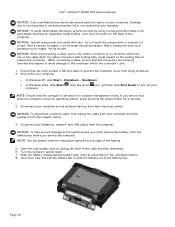
NOTICE: Only a certified service technician should perform repairs on the cable itself. Page 19 Damage due to turn off and not in the unlocked position. 8. NOTICE: To avoid electrostatic discharge, ground yourself by sliding the latch to place them in a power management mode.
Service Manual - Page 20
...Working On Your Computer
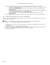
After you have completed the replacement procedures, ensure you connect the external devices, cards...dell.com.
To remove a battery slice, see the documentation that shipped with your battery slice or on your computer. 3. Turn the computer topside up, open the display, and press the power button to their electrical outlets. 5. Dell™ Latitude™ E6400 XFR...
Service Manual - Page 23
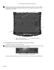
...3 Battery release slider latches (2)
4.2 Replacing the Bottom Access Panel
1.
See photo below . Replace and tighten the twenty-one M2.5 x 5-mm screws in the sequence identified below for correct slider latches positions. Position the Bottom Access Panel into place. Battery release latches in their locked positions. Dell™ Latitude™ E6400 XFR Service Manual
NOTE: No snaps...
Service Manual - Page 25
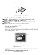
... the appropriate antenna cables to the card you replace it in After Working on Your Computer. NOTICE: Insert a WLAN or WiMax card only into the connector labeled WLAN/WiMax. 2. Follow the procedures in place. 3. Dell™ Latitude™ E6400 XFR Service Manual
1 WLAN/WiMax card 2 Card connector
5.2 Replacing the WLAN/WiMax Card
NOTICE: The connectors are...
Service Manual - Page 44
... on Your Computer.
20 Display Assembly
20.1 Removing the Display Assembly
CAUTION: Before you begin any of the laptop after unrouting. Position all
cables to remove.
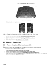
19.2 Replacing the LCD Cable Channel Covers
1. Remove the bottom access panel (see Removing the LCD Cable Channel Covers). 4.
Dell™ Latitude™ E6400 XFR Service Manual
1 1 M2 x 3-mm screws (2) 4.
Service Manual - Page 56
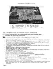
... on the flat area of the bottom access panel. Dell™ Latitude™ E6400 XFR Service Manual
1 JSC1 Smartcard connector 5 JBIO1 BIO reader connector
2 JTP1
Touchpad connector
6 J1394 1394 cable connector
3 JSNIF1 Wi-Fi sniffer connector 7
Multi-mode HD video connector
4 JSPK1 Speaker connector
26.2 Replacing the System Board Assembly
CAUTION: Before you begin any...
Service Manual - Page 57
...section, follow the safety Page 57 Dell™ Latitude™ E6400 XFR Service Manual
20. Follow the procedures in the tech sheet that was shipped with your replacement system board.
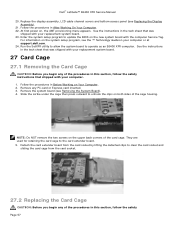
27 Card Cage
27.1...board (see Replacing the Display Assembly).
21. NOTE: Do NOT remove the two screws on Your Computer. 2. See the instructions in After Working On Your Computer. 22. At first power on the...
Service Manual - Page 63
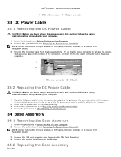
... the connector, and then lift the DC power connector out of the base assembly.
1
2
1 DC power connector 2 DC cable
33.2 Replacing the DC Power Cable
CAUTION: Before you begin any of ...3. Pry up the DC power connector to the base.
2. Dell™ Latitude™ E6400 XFR Service Manual
3 M2.5 x 5-mm screw 4 Modem connector
33 DC Power Cable
33.1 Removing the DC Power Cable
CAUTION: Before you ...
Service Manual - Page 68
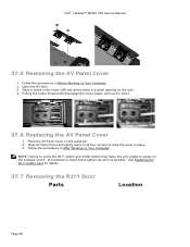
... cover.
37.6 Replacing the AV Panel Cover
1. Follow the procedures in place. 3. Place the AV Panel Cover on Your Computer. Slide AV Panel Cover and lightly press in all four corners to snap the cover in After Working on the guide pin. 2. Open the AV door. 3. Dell™ Latitude™ E6400 XFR Service Manual
37...
Service Manual - Page 70
.... 2. Dell™ Latitude™ E6400 XFR Service Manual
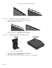
37.10 Replacing the Battery Door
1. Replace the four M3 x 3-mm screws.
3. Open the door to relieve hinge pressure. 3. Remove the two M2.5 x 5-mm screws from the bottom of the base assembly
Page 70 Follow the procedures in Before Working on Your Computer.
37.11 Removing the Power Door...
Service Manual - Page 71
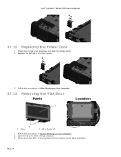
... the procedures in Before Working on Your Computer.
37.13 Removing the VGA Door Parts
Location
1
2 1 Door
2 M3 x 3 mm (2)
1. Page 71 Dell™ Latitude™ E6400 XFR Service Manual
37.12 Replacing the Power Door
1. Insert door hinge onto assembly and align the hinge divots. 2. Open the door to relieve hinge pressure.
3. Remove the two M3...
Similar Questions


