Setup and Features Information Tech Sheet
Page 6
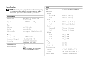
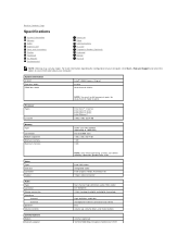
... 6-cell 9-cell Depth 4- and 6-cell 9-cell Weight 4-cell 6-cell 9-cell Voltage 4-cell 6- For more than 4 GB memory Battery Type Dimensions Height 4- System Information Processor type Chipset Intel® Core™ i3, i5, and i7 series Intel Celeron&#...8482; Intel HM55 Express Chipset Video Video type Data bus Video controller Intel UMA video integrated video Intel Graphics Media Accelerator HD Memory Memory module connectors Memory module capacity Memory type Minimum memory Maximum memory two SODIMM slots 1 GB, 2 GB, 4 GB, 8 GB DDR3 1333 MHz SDRAM (operating at 1066 MHz) 1 GB ...
... 6-cell 9-cell Depth 4- and 6-cell 9-cell Weight 4-cell 6-cell 9-cell Voltage 4-cell 6- For more than 4 GB memory Battery Type Dimensions Height 4- System Information Processor type Chipset Intel® Core™ i3, i5, and i7 series Intel Celeron&#...8482; Intel HM55 Express Chipset Video Video type Data bus Video controller Intel UMA video integrated video Intel Graphics Media Accelerator HD Memory Memory module connectors Memory module capacity Memory type Minimum memory Maximum memory two SODIMM slots 1 GB, 2 GB, 4 GB, 8 GB DDR3 1333 MHz SDRAM (operating at 1066 MHz) 1 GB ...
Service Manual
Page 14
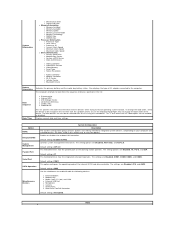
...or disables the onboard LAN controller. System Information ¡ Manufacture Date ¡ Ownership Date l Memory Information ¡ Memory Installed ¡ Memory Available ¡ Memory Speed ¡ Memory Channel Mode ¡ Memory Technology ¡ DIMM A Size ¡ DIMM B Size l Processor Information ¡ Processor Type...Bay Device ¡ System eSATA Device ¡ Dock eSATA Device ¡ Video Controller ¡ Video BIOS Version ¡ Video Memory ¡ Panel Type ¡ Native Resolution ¡ Audio Controller ¡ Modem Controller ¡ Wi-Fi Device ¡ ...
...or disables the onboard LAN controller. System Information ¡ Manufacture Date ¡ Ownership Date l Memory Information ¡ Memory Installed ¡ Memory Available ¡ Memory Speed ¡ Memory Channel Mode ¡ Memory Technology ¡ DIMM A Size ¡ DIMM B Size l Processor Information ¡ Processor Type...Bay Device ¡ System eSATA Device ¡ Dock eSATA Device ¡ Video Controller ¡ Video BIOS Version ¡ Video Memory ¡ Panel Type ¡ Native Resolution ¡ Audio Controller ¡ Modem Controller ¡ Wi-Fi Device ¡ ...
Service Manual
Page 16
... system, handles USB devices. The factory default setting is Disabled. l By Num Lk - Boot quickly unless the BIOS has been updated, memory changed, or the previous POST did not complete. Option Virtualization VT for Direct I /O Virtualization Support Description This field specifies whether a Virtual .... This field lets you are running an ACPI operating system such as Microsoft® Windows® XP. ExpressCharge™ = Dell fast charging technology (not available for USB devices to wake the system from Standby. If disabled, the battery will not charge ...
... system, handles USB devices. The factory default setting is Disabled. l By Num Lk - Boot quickly unless the BIOS has been updated, memory changed, or the previous POST did not complete. Option Virtualization VT for Direct I /O Virtualization Support Description This field specifies whether a Virtual .... This field lets you are running an ACPI operating system such as Microsoft® Windows® XP. ExpressCharge™ = Dell fast charging technology (not available for USB devices to wake the system from Standby. If disabled, the battery will not charge ...
Service Manual
Page 22
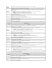
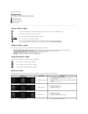
... already present, reseat the module(s) one at a time in a no-Power On Self Test (POST) situation. Try known good memory from another computer or replace the memory. 4. Replace the system board. 3. Turns on - Turns on when a card with AC adapter present. Battery Status Lights If ...shows the possible LED codes that may display in each slot. 3. Replace the LCD panel. 3. Back to Contents Page Diagnostics Dell™ Latitude™ E5410 Discrete Service Manual Device Status Lights Battery Status Lights Keyboard Status Lights LED Error Codes Device Status Lights Turns on when you ...
... already present, reseat the module(s) one at a time in a no-Power On Self Test (POST) situation. Try known good memory from another computer or replace the memory. 4. Replace the system board. 3. Turns on - Turns on when a card with AC adapter present. Battery Status Lights If ...shows the possible LED codes that may display in each slot. 3. Replace the LCD panel. 3. Back to Contents Page Diagnostics Dell™ Latitude™ E5410 Discrete Service Manual Device Status Lights Battery Status Lights Keyboard Status Lights LED Error Codes Device Status Lights Turns on when you ...
Service Manual
Page 23
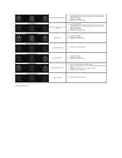
...board error 1. Video card error 1. Test the other slot with both modules. 3. Replace the modem. 3. Replace the system board. Replace the memory. 4. Replace the system board. Option ROM error 1. Replace the device that is detected but has errors 1. Replace the system board. Replace ...the system board. If two modules are installed, remove one and test. Replace the memory. 4. Storage device error 1. Replace the system board. Reseat the modem. 2. Reseat the device. 2. Replace the system board. Modem error...
...board error 1. Video card error 1. Test the other slot with both modules. 3. Replace the modem. 3. Replace the system board. Replace the memory. 4. Replace the system board. Option ROM error 1. Replace the device that is detected but has errors 1. Replace the system board. Replace ...the system board. If two modules are installed, remove one and test. Replace the memory. 4. Storage device error 1. Replace the system board. Reseat the modem. 2. Reseat the device. 2. Replace the system board. Modem error...
Service Manual
Page 47
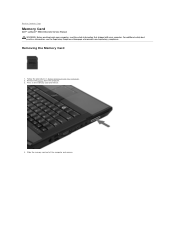
Press in Before Working Inside Your Computer. 2. For additional safety best practices information, see the Regulatory Compliance Homepage at www.dell.com/regulatory_compliance. Removing the Memory Card 1. Slide the memory card out of the computer and remove. Back to Contents Page Memory Card Dell™ Latitude™ E5410 Discrete Service Manual WARNING: Before working inside your computer, read the safety information that shipped with your computer. Follow the procedures in the memory card and release. 4. Remove the battery from the computer. 3.
Press in Before Working Inside Your Computer. 2. For additional safety best practices information, see the Regulatory Compliance Homepage at www.dell.com/regulatory_compliance. Removing the Memory Card 1. Slide the memory card out of the computer and remove. Back to Contents Page Memory Card Dell™ Latitude™ E5410 Discrete Service Manual WARNING: Before working inside your computer, read the safety information that shipped with your computer. Follow the procedures in the memory card and release. 4. Remove the battery from the computer. 3.
Service Manual
Page 48
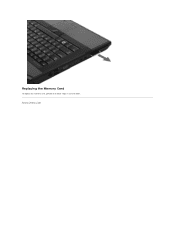
Back to Contents Page Replacing the Memory Card To replace the memory card, perform the above steps in reverse order.
Back to Contents Page Replacing the Memory Card To replace the memory card, perform the above steps in reverse order.
Service Manual
Page 49
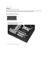
... Before Working Inside Your Computer. 2. Remove the battery from the computer. For additional safety best practices information, see the Regulatory Compliance Homepage at www.dell.com/regulatory_compliance. Back to Contents Page Memory Dell™ Latitude™ E5410 Discrete Service Manual WARNING: Before working inside your computer, read the safety information that shipped with your computer.
... Before Working Inside Your Computer. 2. Remove the battery from the computer. For additional safety best practices information, see the Regulatory Compliance Homepage at www.dell.com/regulatory_compliance. Back to Contents Page Memory Dell™ Latitude™ E5410 Discrete Service Manual WARNING: Before working inside your computer, read the safety information that shipped with your computer.
Service Manual
Page 50
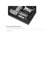
Back to Contents Page Replacing the Memory Modules To replace the memory modules, perform the above steps in reverse order.
Back to Contents Page Replacing the Memory Modules To replace the memory modules, perform the above steps in reverse order.
Service Manual
Page 51
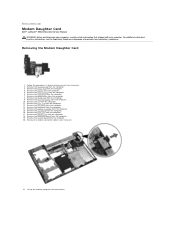
... the fan from the computer. 3. For additional safety best practices information, see the Regulatory Compliance Homepage at www.dell.com/regulatory_compliance. Remove the memory card from the computer. 11. Remove the modem connector rubber cover if present. 21. Remove the display assembly ... from the computer. 20. Remove the system board from the computer. 9. Back to Contents Page Modem Daughter Card Dell™ Latitude™ E5410 Discrete Service Manual WARNING: Before working inside your computer, read the safety information that shipped with your computer. Follow the...
... the fan from the computer. 3. For additional safety best practices information, see the Regulatory Compliance Homepage at www.dell.com/regulatory_compliance. Remove the memory card from the computer. 11. Remove the modem connector rubber cover if present. 21. Remove the display assembly ... from the computer. 20. Remove the system board from the computer. 9. Back to Contents Page Modem Daughter Card Dell™ Latitude™ E5410 Discrete Service Manual WARNING: Before working inside your computer, read the safety information that shipped with your computer. Follow the...
Service Manual
Page 61
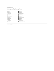
Back to Contents Page Adding and Replacing Parts Dell™ Latitude™ E5410 Discrete Service Manual Battery Phone SIM Access Panel LED Cover WLAN Card Memory Coin-Cell Battery Hard Drive Optical Drive Keyboard Memory Card Fan Heat Sink Processor LED Board Display Assembly Display Bezel Display Panel, Bracket and Hinges Display Camera Palm Rest Fingerprint Reader WWAN Card Speakers Bluetooth Board System Board Modem Daughter Card Back to Contents Page
Back to Contents Page Adding and Replacing Parts Dell™ Latitude™ E5410 Discrete Service Manual Battery Phone SIM Access Panel LED Cover WLAN Card Memory Coin-Cell Battery Hard Drive Optical Drive Keyboard Memory Card Fan Heat Sink Processor LED Board Display Assembly Display Bezel Display Panel, Bracket and Hinges Display Camera Palm Rest Fingerprint Reader WWAN Card Speakers Bluetooth Board System Board Modem Daughter Card Back to Contents Page
Service Manual
Page 70
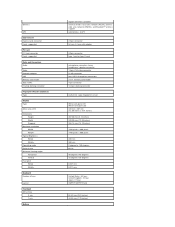
...high-definition audio (HDA) codec IDT 92HD81B 24-bit (analog-to-digital and digital-to Contents Page Specifications System Information Memory Audio ExpressCard Ports and Connectors Display Touchpad AC Adapter Environmental Processor Video Communications PC Card Fingerprint Reader (Optional) Keyboard Battery ...width Intel® HM55 Express Chipset 64 bits dual-channel 64 bits Processor Types L2 cache Memory Type Connectors Module capacities Minimum memory Maximum memory NOTE: You must install memory in connector and stereo two volume up, volume down, and mute buttons internal (optional) ...
...high-definition audio (HDA) codec IDT 92HD81B 24-bit (analog-to-digital and digital-to Contents Page Specifications System Information Memory Audio ExpressCard Ports and Connectors Display Touchpad AC Adapter Environmental Processor Video Communications PC Card Fingerprint Reader (Optional) Keyboard Battery ...width Intel® HM55 Express Chipset 64 bits dual-channel 64 bits Processor Types L2 cache Memory Type Connectors Module capacities Minimum memory Maximum memory NOTE: You must install memory in connector and stereo two volume up, volume down, and mute buttons internal (optional) ...
Service Manual
Page 71
...GPS ExpressCard ExpressCard connector Cards supported PC Card PC Card connector Cards supported Ports and Connectors Audio Video Network adapter USB Memory card reader IEEE 1394a E-family docking connector Fingerprint Reader (Optional) Type Display Type Active area (X/Y) Dimensions Height Width ...type II card microphone connector stereo headphone/ speaker connector 15-pin VGA video connector RJ-45 connector four USB 2.0-compliant connectors 3-in-1 memory card reader 4-pin connector 144-pin docking connector AuthenTec swipe fingerprint sensor WXGA anti-glare LED WXGA+anti-glare LED 320 mm x...
...GPS ExpressCard ExpressCard connector Cards supported PC Card PC Card connector Cards supported Ports and Connectors Audio Video Network adapter USB Memory card reader IEEE 1394a E-family docking connector Fingerprint Reader (Optional) Type Display Type Active area (X/Y) Dimensions Height Width ...type II card microphone connector stereo headphone/ speaker connector 15-pin VGA video connector RJ-45 connector four USB 2.0-compliant connectors 3-in-1 memory card reader 4-pin connector 144-pin docking connector AuthenTec swipe fingerprint sensor WXGA anti-glare LED WXGA+anti-glare LED 320 mm x...
Service Manual
Page 74
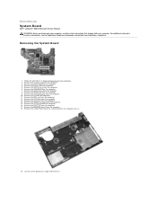
...memory card from the computer. 7. Remove the hard drive from the computer. 3. Remove the WLAN card from the computer. 10. Remove the coin-cell battery from the computer. 9. Remove the fan from the computer. 5. Remove the screws that secure the system board to Contents Page System Board Dell™ Latitude™ E5410...assembly from the computer. 18. Remove the Bluetooth board from the computer. 15. Lift the system board at www.dell.com/regulatory_compliance. Follow the procedures in Before Working Inside Your Computer. 2. Remove the LED cover from the computer. 14...
...memory card from the computer. 7. Remove the hard drive from the computer. 3. Remove the WLAN card from the computer. 10. Remove the coin-cell battery from the computer. 9. Remove the fan from the computer. 5. Remove the screws that secure the system board to Contents Page System Board Dell™ Latitude™ E5410...assembly from the computer. 18. Remove the Bluetooth board from the computer. 15. Lift the system board at www.dell.com/regulatory_compliance. Follow the procedures in Before Working Inside Your Computer. 2. Remove the LED cover from the computer. 14...


