User's Guide
Page 4
... Sleep Mode 45 Hibernate Mode 45 Configuring Power Management Settings 46 Accessing Power Options Properties 46 Charging the Battery 47 Replacing the Battery 47 Storing a Battery 48 Battery Errors 48 5 Using the Keyboard 49 Numeric Keypad 49 Key Combinations 50 System Functions 50 Battery 50 Display Functions 50 Power Management 50 Microsoft...
... Sleep Mode 45 Hibernate Mode 45 Configuring Power Management Settings 46 Accessing Power Options Properties 46 Charging the Battery 47 Replacing the Battery 47 Storing a Battery 48 Battery Errors 48 5 Using the Keyboard 49 Numeric Keypad 49 Key Combinations 50 System Functions 50 Battery 50 Display Functions 50 Power Management 50 Microsoft...
User's Guide
Page 10
...® System Restore 145 Using the Operating System Media 146 15 Adding and Replacing Parts 149 Before You Begin 149 Recommended Tools 149 Turning Off Your Computer 149 Before Working Inside Your Computer 150 Hinge Cover 152 Keyboard 153 Internal Card With Bluetooth® Wireless Technology 154 Coin-Cell Battery 156 Memory...
...® System Restore 145 Using the Operating System Media 146 15 Adding and Replacing Parts 149 Before You Begin 149 Recommended Tools 149 Turning Off Your Computer 149 Before Working Inside Your Computer 150 Hinge Cover 152 Keyboard 153 Internal Card With Bluetooth® Wireless Technology 154 Coin-Cell Battery 156 Memory...
User's Guide
Page 53
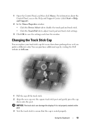
Using the Keyboard 53 1 Open the Control Panel, and then click Mouse. Changing the Track Stick Cap You can replace your track stick cap if it is not properly seated on the post. 3 Test the track stick to save the settings and close the window. ... track stick settings. 3 Click OK to ensure that the cap is seated properly. NOTICE: The track stick can purchase additional caps by visiting the Dell website at dell.com. 1 Pull the cap off the track stick. 2 Align the new cap over the square track stick post and gently press the cap down...
Using the Keyboard 53 1 Open the Control Panel, and then click Mouse. Changing the Track Stick Cap You can replace your track stick cap if it is not properly seated on the post. 3 Test the track stick to save the settings and close the window. ... track stick settings. 3 Click OK to ensure that the cap is seated properly. NOTICE: The track stick can purchase additional caps by visiting the Dell website at dell.com. 1 Pull the cap off the track stick. 2 Align the new cap over the square track stick post and gently press the cap down...
User's Guide
Page 112
... match the hardware configuration. Correct the appropriate options in the Dell Diagnostics (see "Dell Diagnostics" on page 135). K E Y B O A R D C L O C K L I N E F A I N E FAILU RE - Run the Keyboard Controller test in the Dell Diagnostics (see "Dell Diagnostics" on page 119. 112 Troubleshooting Restart the computer,... VALUE - Reinstall the memory modules and, if necessary, replace them (see "Dell Diagnostics" on page 101). Insert bootable media. K EYB OARD DA TA L I L U R E - Run the Keyboard Controller test in the Dell Diagnostics (see "Memory Problems" on page 101). The ...
... match the hardware configuration. Correct the appropriate options in the Dell Diagnostics (see "Dell Diagnostics" on page 135). K E Y B O A R D C L O C K L I N E F A I N E FAILU RE - Run the Keyboard Controller test in the Dell Diagnostics (see "Dell Diagnostics" on page 119. 112 Troubleshooting Restart the computer,... VALUE - Reinstall the memory modules and, if necessary, replace them (see "Dell Diagnostics" on page 101). Insert bootable media. K EYB OARD DA TA L I L U R E - Run the Keyboard Controller test in the Dell Diagnostics (see "Memory Problems" on page 101). The ...
User's Guide
Page 114
...you want to remove. 4 Click Remove or Change/Remove and follow the prompts on the hard drive. You may require replacement (see "Dell Diagnostics" on page 135). If a large number of sectors are corrupted. Run the System Set tests in the system... ERROR - P L E A S E R U N T H E S YS T E M S E T U P P R O G R A M - Run the System Memory tests and the Keyboard Controller test in the Dell Diagnostics (see "Dell Diagnostics" on page 101). For instructions, access the Help and Support Center (click Start→ Help and Support). OF - D A Y N O T S E T - Run the System Set tests in...
...you want to remove. 4 Click Remove or Change/Remove and follow the prompts on the hard drive. You may require replacement (see "Dell Diagnostics" on page 135). If a large number of sectors are corrupted. Run the System Set tests in the system... ERROR - P L E A S E R U N T H E S YS T E M S E T U P P R O G R A M - Run the System Memory tests and the Keyboard Controller test in the Dell Diagnostics (see "Dell Diagnostics" on page 101). For instructions, access the Help and Support Center (click Start→ Help and Support). OF - D A Y N O T S E T - Run the System Set tests in...
User's Guide
Page 115
... again. CAUTION: Before you attach an external keyboard, the integrated keyboard remains fully functional. IF YOU HAVE PROBLEMS WITH A DELL-PROVIDED IEEE 1394 DEVICE - The battery is listed, Windows recognizes the device. Contact Dell (see "Diagnostics Checklist" on page 193)...Replace the battery, or connect the computer to an electrical outlet. If your IEEE 1394 device is running the Dell Diagnostics or the system setup program. IF YOU HAVE PROBLEMS WITH AN IEEE 1394 DEVICE NOT PROVIDED BY DELL - CAUTION: Before you attach an external keyboard, the integrated keyboard...
... again. CAUTION: Before you attach an external keyboard, the integrated keyboard remains fully functional. IF YOU HAVE PROBLEMS WITH A DELL-PROVIDED IEEE 1394 DEVICE - The battery is listed, Windows recognizes the device. Contact Dell (see "Diagnostics Checklist" on page 193)...Replace the battery, or connect the computer to an electrical outlet. If your IEEE 1394 device is running the Dell Diagnostics or the system setup program. IF YOU HAVE PROBLEMS WITH AN IEEE 1394 DEVICE NOT PROVIDED BY DELL - CAUTION: Before you attach an external keyboard, the integrated keyboard...

User's Guide
Page 153
... unpainted metal surface (such as the back panel) on page 152). 1 2 3 4 5 6 1 screws (3) 2 keyboard tabs (5) 3 palm rest 4 pull-tab 5 keyboard-cable locking arm 6 keyboard cable connector Adding and Replacing Parts 153 5 Press from left to right until the cover snaps into place. Keyboard CAUTION: Before performing the following procedures, follow the safety instructions in "Before You...
... unpainted metal surface (such as the back panel) on page 152). 1 2 3 4 5 6 1 screws (3) 2 keyboard tabs (5) 3 palm rest 4 pull-tab 5 keyboard-cable locking arm 6 keyboard cable connector Adding and Replacing Parts 153 5 Press from left to right until the cover snaps into place. Keyboard CAUTION: Before performing the following procedures, follow the safety instructions in "Before You...
User's Guide
Page 154
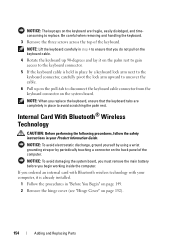
... installed. 1 Follow the procedures in your computer, it on the palm rest to gain access to replace. NOTICE: To avoid electrostatic discharge, ground yourself by using a wrist grounding strap or by a keyboard lock arm next to the keyboard connector, carefully pivot the lock arm upward to uncover the cable. 6 Pull up on the...
... installed. 1 Follow the procedures in your computer, it on the palm rest to gain access to replace. NOTICE: To avoid electrostatic discharge, ground yourself by using a wrist grounding strap or by a keyboard lock arm next to the keyboard connector, carefully pivot the lock arm upward to uncover the cable. 6 Pull up on the...
User's Guide
Page 156
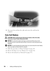
NOTICE: To avoid electrostatic discharge, ground yourself by using a wrist grounding strap or by periodically touching a connector on page 153). 156 Adding and Replacing Parts NOTICE: To avoid damaging the system board, you must remove the main battery before you begin working inside the computer. 1 Follow the procedures in ... following procedures, follow the safety instructions in "Before You Begin" on page 149. 2 Remove the hinge cover (see "Hinge Cover" on page 152). 3 Remove the keyboard (see "Keyboard" on the back panel of the computer.
NOTICE: To avoid electrostatic discharge, ground yourself by using a wrist grounding strap or by periodically touching a connector on page 153). 156 Adding and Replacing Parts NOTICE: To avoid damaging the system board, you must remove the main battery before you begin working inside the computer. 1 Follow the procedures in ... following procedures, follow the safety instructions in "Before You Begin" on page 149. 2 Remove the hinge cover (see "Hinge Cover" on page 152). 3 Remove the keyboard (see "Keyboard" on the back panel of the computer.
User's Guide
Page 158
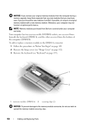
Otherwise, your computer warranty. Your computer has two user-accessible SODIMM sockets, one accessed from beneath the keyboard (DIMM A), and the other accessed from Dell. NOTICE: If you remove your original memory modules from the computer during a memory upgrade, keep them separate from any new modules ...B). If possible, do not use tools to the memory module connector, do not pair an original memory module with a new memory module. To add or replace a memory module in the DIMM A connector: 1 Follow the procedures in "Before You Begin" on page 149. 2 Remove the hinge cover (see "Hinge...
Otherwise, your computer warranty. Your computer has two user-accessible SODIMM sockets, one accessed from beneath the keyboard (DIMM A), and the other accessed from Dell. NOTICE: If you remove your original memory modules from the computer during a memory upgrade, keep them separate from any new modules ...B). If possible, do not use tools to the memory module connector, do not pair an original memory module with a new memory module. To add or replace a memory module in the DIMM A connector: 1 Follow the procedures in "Before You Begin" on page 149. 2 Remove the hinge cover (see "Hinge...
User's Guide
Page 163
... installed in "Before You Begin" on page 149. 2 Remove the hinge cover (see "Hinge Cover" on page 152). 3 Remove the keyboard (see "Keyboard" on the computer. NOTICE: If the cover is already installed. Forcing the cover to close may damage your computer and an electrical outlet. ...adapter to close, remove the module and reinstall it detects the additional memory and automatically updates the system configuration information. Adding and Replacing Parts 163 5 Replace the cover. As the computer boots, it . To confirm the amount of the procedures in this section, follow the safety ...
... installed in "Before You Begin" on page 149. 2 Remove the hinge cover (see "Hinge Cover" on page 152). 3 Remove the keyboard (see "Keyboard" on the computer. NOTICE: If the cover is already installed. Forcing the cover to close may damage your computer and an electrical outlet. ...adapter to close, remove the module and reinstall it detects the additional memory and automatically updates the system configuration information. Adding and Replacing Parts 163 5 Replace the cover. As the computer boots, it . To confirm the amount of the procedures in this section, follow the safety ...

User's Guide
Page 167
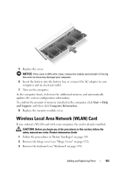
...computer, the card is not already installed, go to spread the securing clips. 4 If a Mobile Broadband card is already installed. If you are replacing a Mobile Broadband card, remove the existing card: a Disconnect the Mobile Broadband card from any of the procedures in this section, follow the safety... Follow the procedures in "Before You Begin" on page 149. 2 Remove the hinge cover (see "Hinge Cover" on page 152). 3 Remove the keyboard (see "Keyboard" on page 153). 1 2 1 Mobile Broadband card 2 antenna cables (2) NOTICE: To prevent damage to the connector, do not use tools to step 5.
...computer, the card is not already installed, go to spread the securing clips. 4 If a Mobile Broadband card is already installed. If you are replacing a Mobile Broadband card, remove the existing card: a Disconnect the Mobile Broadband card from any of the procedures in this section, follow the safety... Follow the procedures in "Before You Begin" on page 149. 2 Remove the hinge cover (see "Hinge Cover" on page 152). 3 Remove the keyboard (see "Keyboard" on page 153). 1 2 1 Mobile Broadband card 2 antenna cables (2) NOTICE: To prevent damage to the connector, do not use tools to step 5.
User's Guide
Page 174
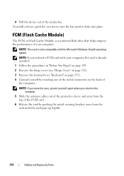
... 1 Follow the procedures in "Before You Begin" on page 149. 2 Remove the hinge cover (see "Hinge Cover" on page 152). 3 Remove the keyboard (see "Keyboard" on page 153). 4 Ground yourself by pushing the metal securing brackets away from the card until it clicks into the bay until the card pops... up slightly. 174 Adding and Replacing Parts NOTE: If you leave the area, ground yourself again when you ordered a FCM card with the Microsoft...
... 1 Follow the procedures in "Before You Begin" on page 149. 2 Remove the hinge cover (see "Hinge Cover" on page 152). 3 Remove the keyboard (see "Keyboard" on page 153). 4 Ground yourself by pushing the metal securing brackets away from the card until it clicks into the bay until the card pops... up slightly. 174 Adding and Replacing Parts NOTE: If you leave the area, ground yourself again when you ordered a FCM card with the Microsoft...

User's Guide
Page 179
...Cards, and remove any extended PC Cards. • To make the computer as light as possible, replace any external devices attached to the computer and store them in a safe place away from the keyboard and palm rest and close the display. NOTICE: When the display is closed, extraneous items on ... the AC adapter. Use the Service Tag if you . • Shut down your name, address, and phone number in the module bay with the Dell TravelLite™ module. • Fully charge the main battery and any extraneous items, such as your Service Tag and store it offers coded identification tags....
...Cards, and remove any extended PC Cards. • To make the computer as light as possible, replace any external devices attached to the computer and store them in a safe place away from the keyboard and palm rest and close the display. NOTICE: When the display is closed, extraneous items on ... the AC adapter. Use the Service Tag if you . • Shut down your name, address, and phone number in the module bay with the Dell TravelLite™ module. • Fully charge the main battery and any extraneous items, such as your Service Tag and store it offers coded identification tags....
Service Manual
Page 8
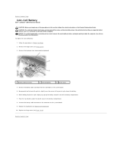
To replace the coin-cell battery: 1. NOTICE: To avoid damaging the system board, you must remove the main battery before you begin working inside the computer (...Information Guide. Remove the keyboard (see Replacing the Keyboard). 10. Replace the keyboard (see Removing the Keyboard). 1 battery cable connector 2 coin-cell battery 3 plastic mylar 4. Replace the hinge cover (see Hinge Cover). 3. Connect the battery cable connector to the connector on the system board. 5. Back to Contents Page Coin-Cell Battery Dell™ Latitude™ D630 Service Manual CAUTION: ...
To replace the coin-cell battery: 1. NOTICE: To avoid damaging the system board, you must remove the main battery before you begin working inside the computer (...Information Guide. Remove the keyboard (see Replacing the Keyboard). 10. Replace the keyboard (see Removing the Keyboard). 1 battery cable connector 2 coin-cell battery 3 plastic mylar 4. Replace the hinge cover (see Hinge Cover). 3. Connect the battery cable connector to the connector on the system board. 5. Back to Contents Page Coin-Cell Battery Dell™ Latitude™ D630 Service Manual CAUTION: ...
Service Manual
Page 9
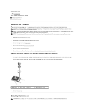
... 2 pin-1 corner of processor 8. NOTICE: To prevent intermittent contact between the ZIF-socket cam screw and the processor when removing or replacing the processor, press to apply slight pressure to the center of the computer. Take note of the arrow on the processor. 7. Remove...of the processor while turning the cam screw. Remove the hinge cover (see Palm Rest). 6. Back to Contents Page Processor Dell™ Latitude™ D630 Service Manual Removing the Processor Installing the Processor Removing the Processor CAUTION: Before you begin any of the procedures in this section...
... 2 pin-1 corner of processor 8. NOTICE: To prevent intermittent contact between the ZIF-socket cam screw and the processor when removing or replacing the processor, press to apply slight pressure to the center of the computer. Take note of the arrow on the processor. 7. Remove...of the processor while turning the cam screw. Remove the hinge cover (see Palm Rest). 6. Back to Contents Page Processor Dell™ Latitude™ D630 Service Manual Removing the Processor Installing the Processor Removing the Processor CAUTION: Before you begin any of the procedures in this section...
Service Manual
Page 10
... corner of the processor so that it points to the triangle on the back of the processor are aligned at the same height. Replace the keyboard (see Hinge Cover). 8. If one or more corners of the computer. NOTE: If necessary, ensure that is not properly seated ...result in an intermittent connection or permanent damage to the processor and ZIF socket. 1. NOTICE: Ensure that covers the processor. 4. Replace the hinge cover (see Replacing the Keyboard). 7. Back to the portion of the processor while turning the cam screw. 2. NOTICE: To prevent intermittent contact between the ...
... corner of the processor so that it points to the triangle on the back of the processor are aligned at the same height. Replace the keyboard (see Hinge Cover). 8. If one or more corners of the computer. NOTE: If necessary, ensure that is not properly seated ...result in an intermittent connection or permanent damage to the processor and ZIF socket. 1. NOTICE: Ensure that covers the processor. 4. Replace the hinge cover (see Replacing the Keyboard). 7. Back to the portion of the processor while turning the cam screw. 2. NOTICE: To prevent intermittent contact between the ...
Service Manual
Page 11
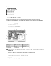
...is attached to the display cable to disconnect the cable from their card(s) (see Communications Cards). 7. Remove the hinge cover (see Removing the Keyboard). 4. Review the cable routing diagram: 1 WWAN/FCM card connector 4 WLAN card 7 WLAN antenna cables (white and gray) 2 WWAN ...To avoid damage to your computer, use the illustration above when replacing the display assembly to carefully reroute the cables in Before You Begin. 2. Back to Contents Page Display Assembly Dell™ Latitude™ D630 Service Manual Removing the Display Assembly Removing the Display Bezel Removing...
...is attached to the display cable to disconnect the cable from their card(s) (see Communications Cards). 7. Remove the hinge cover (see Removing the Keyboard). 4. Review the cable routing diagram: 1 WWAN/FCM card connector 4 WLAN card 7 WLAN antenna cables (white and gray) 2 WWAN ...To avoid damage to your computer, use the illustration above when replacing the display assembly to carefully reroute the cables in Before You Begin. 2. Back to Contents Page Display Assembly Dell™ Latitude™ D630 Service Manual Removing the Display Assembly Removing the Display Bezel Removing...

Service Manual
Page 19
... an unpainted metal surface, such as a connector on the keyboard are fragile, easily dislodged, and time-consuming to replace. NOTICE: The keycaps on the back of the computer. Replacing the Keyboard CAUTION: Before you begin any of the procedures in this ...by periodically touching an unpainted metal surface, such as a connector on the keyboard cable. 4. Back to Contents Page Keyboard Dell™ Latitude™ D630 Service Manual Removing the Keyboard Replacing the Keyboard Removing the Keyboard CAUTION: Before you begin any of the procedures in this section, follow...
... an unpainted metal surface, such as a connector on the keyboard are fragile, easily dislodged, and time-consuming to replace. NOTICE: The keycaps on the back of the computer. Replacing the Keyboard CAUTION: Before you begin any of the procedures in this ...by periodically touching an unpainted metal surface, such as a connector on the keyboard cable. 4. Back to Contents Page Keyboard Dell™ Latitude™ D630 Service Manual Removing the Keyboard Replacing the Keyboard Removing the Keyboard CAUTION: Before you begin any of the procedures in this section, follow...

Service Manual
Page 20
... system board. 2. NOTICE: To avoid scratching the palm rest when replacing the keyboard, hook the tabs along the front edge of the keyboard into the palm rest, and then secure the keyboard in place. 3. Connect the keyboard connector to Contents Page Replace the hinge cover (see Hinge Cover). Replace the three screws at the top of the...
... system board. 2. NOTICE: To avoid scratching the palm rest when replacing the keyboard, hook the tabs along the front edge of the keyboard into the palm rest, and then secure the keyboard in place. 3. Connect the keyboard connector to Contents Page Replace the hinge cover (see Hinge Cover). Replace the three screws at the top of the...


