Service Manual
Page 1
Dell™ Latitude™ D530 Service Manual Before You Begin Internal Card With Bluetooth ® Wireless Technology Hard Drive Memory Module Modem Coin-Cell Battery Hinge Cover Keyboard Mini-Card Display Assembly Palm Rest System Fan Processor Thermal-Cooling Assembly Processor Module Speaker Assembly Base Latch System Board Assembly Flashing the BIOS Pin ...
Dell™ Latitude™ D530 Service Manual Before You Begin Internal Card With Bluetooth ® Wireless Technology Hard Drive Memory Module Modem Coin-Cell Battery Hinge Cover Keyboard Mini-Card Display Assembly Palm Rest System Fan Processor Thermal-Cooling Assembly Processor Module Speaker Assembly Base Latch System Board Assembly Flashing the BIOS Pin ...
Service Manual
Page 8
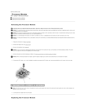
... (such as the back panel) on which indicates the direction to the processor when turning the cam screw. Remove the hinge cover (see Before Working Inside Your Computer) before working inside the computer. 1. NOTICE: When removing the processor module, pull the module... the processor thermal-cooling assembly (see Keyboard). Replacing the Processor Module Back to the processor, hold the processor down on the substrate on the computer. NOTICE: To avoid damage to Contents Page Processor Module Dell™ Latitude™ D530 Service Manual Removing the Processor Module Replacing...
... (such as the back panel) on which indicates the direction to the processor when turning the cam screw. Remove the hinge cover (see Before Working Inside Your Computer) before working inside the computer. 1. NOTICE: When removing the processor module, pull the module... the processor thermal-cooling assembly (see Keyboard). Replacing the Processor Module Back to the processor, hold the processor down on the substrate on the computer. NOTICE: To avoid damage to Contents Page Processor Module Dell™ Latitude™ D530 Service Manual Removing the Processor Module Replacing...
Service Manual
Page 10
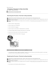
...assembly 3 captive screws (6) 8. Disconnect the three Mini-Card antenna cables (see Keyboard). 4. Replacing the Processor Thermal-Cooling Assembly CAUTION: Before you begin the following ... the three antenna cables from the display cable connector on the computer. Remove the hinge cover (see Before Working Inside Your Computer) before working inside the computer. 1. In consecutive ...from the computer. Back to Contents Page Processor Thermal-Cooling Assembly Dell™ Latitude™ D530 Service Manual Removing the Processor Thermal-Cooling Assembly Replacing the Processor Thermal...
...assembly 3 captive screws (6) 8. Disconnect the three Mini-Card antenna cables (see Keyboard). 4. Replacing the Processor Thermal-Cooling Assembly CAUTION: Before you begin the following ... the three antenna cables from the display cable connector on the computer. Remove the hinge cover (see Before Working Inside Your Computer) before working inside the computer. 1. In consecutive ...from the computer. Back to Contents Page Processor Thermal-Cooling Assembly Dell™ Latitude™ D530 Service Manual Removing the Processor Thermal-Cooling Assembly Replacing the Processor Thermal...
Service Manual
Page 12
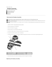
... the hinge cover (see Mini-Card). 7. Replacing the Display Assembly Remove the four M2.5 x 5-mm screws from the display and remove the display from the computer. Back to the system board, remove the main battery (see Keyboard). 4. NOTICE: To help prevent damage to Contents Page Display Assembly Dell™ Latitude™ D530 Service Manual Removing...
... the hinge cover (see Mini-Card). 7. Replacing the Display Assembly Remove the four M2.5 x 5-mm screws from the display and remove the display from the computer. Back to the system board, remove the main battery (see Keyboard). 4. NOTICE: To help prevent damage to Contents Page Display Assembly Dell™ Latitude™ D530 Service Manual Removing...
Service Manual
Page 13
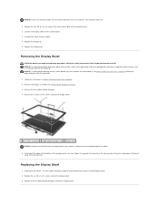
... around the display bezel. 1 M2 x 5-mm screws(6) 2 rubber display bumpers (5) 3 display bezel NOTICE: Removal of the bezel from the top cover. Replace the keyboard. 5. NOTICE: To help prevent damage to the computer base. 2. Starting at the edges of the bottom of the bezel away from the display back... cover requires extreme care to avoid damage to the system board. 3. Remove the five rubber display bumpers. 4. Starting at any corner...
... around the display bezel. 1 M2 x 5-mm screws(6) 2 rubber display bumpers (5) 3 display bezel NOTICE: Removal of the bezel from the top cover. Replace the keyboard. 5. NOTICE: To help prevent damage to the computer base. 2. Starting at the edges of the bottom of the bezel away from the display back... cover requires extreme care to avoid damage to the system board. 3. Remove the five rubber display bumpers. 4. Starting at any corner...
Service Manual
Page 21
IDE - I /O devices. Keyboards and printers are I /O - An address in RAM that is associated with a specific device (such as 1000 bytes. interrupt request - ISP - A company that device. K Kb - KB - A computer network covering a small area. liquid crystal display - light-emitting diode - line print ... is a small external card that provides a fast throughput for a parallel connection to as optical drives, a second battery, or a Dell TravelLite™ module. One million bits per second. Also referred to a printer or other parallel device. A port that allows you ...
IDE - I /O devices. Keyboards and printers are I /O - An address in RAM that is associated with a specific device (such as 1000 bytes. interrupt request - ISP - A company that device. K Kb - KB - A computer network covering a small area. liquid crystal display - light-emitting diode - line print ... is a small external card that provides a fast throughput for a parallel connection to as optical drives, a second battery, or a Dell TravelLite™ module. One million bits per second. Also referred to a printer or other parallel device. A port that allows you ...

Service Manual
Page 24
... editor - The circuitry on a video card or on a metal sheath around each other over the air waves using cellular technology and covering a much larger geographic area than relying on the system board (in computers with an integrated video controller) that when combined with the ... a 3.5-inch floppy disk, slide its embedded virus also starts. A utility that can also scan in video modes that serves as a USB-compatible keyboard, mouse, joystick, scanner, set of cable used to create and edit files that is left in most telephone networks and some computer networks. Describes...
... editor - The circuitry on a video card or on a metal sheath around each other over the air waves using cellular technology and covering a much larger geographic area than relying on the system board (in computers with an integrated video controller) that when combined with the ... a 3.5-inch floppy disk, slide its embedded virus also starts. A utility that can also scan in video modes that serves as a USB-compatible keyboard, mouse, joystick, scanner, set of cable used to create and edit files that is left in most telephone networks and some computer networks. Describes...
Service Manual
Page 29
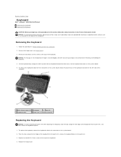
...hinge cover (see Hinge Cover). 3. Be careful when removing and handling the keyboard. 4. To replace the keyboard, connect the keyboard cable to the left side of the computer. 1 M2.5 x 5-mm screws (2) 2 Keyboard 3 tabs (5) 4 keyboard cable 5 plastic bar on keyboard connector Replacing the Keyboard ... Your Computer. 2. Back to Contents Page Keyboard Dell™ Latitude™ D530 Service Manual Removing the Keyboard Replacing the Keyboard CAUTION: Before you begin any of the keyboard. 4. Removing the Keyboard 1. To release the keyboard cable from the connector on the system board...
...hinge cover (see Hinge Cover). 3. Be careful when removing and handling the keyboard. 4. To replace the keyboard, connect the keyboard cable to the left side of the computer. 1 M2.5 x 5-mm screws (2) 2 Keyboard 3 tabs (5) 4 keyboard cable 5 plastic bar on keyboard connector Replacing the Keyboard ... Your Computer. 2. Back to Contents Page Keyboard Dell™ Latitude™ D530 Service Manual Removing the Keyboard Replacing the Keyboard CAUTION: Before you begin any of the keyboard. 4. Removing the Keyboard 1. To release the keyboard cable from the connector on the system board...
Service Manual
Page 32
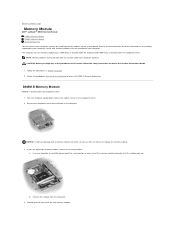
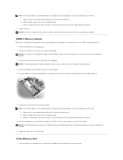
... instructions located in Before You Begin 2. DIMM A bay is located under the keyboard and DIMM B bay is located under the component cover. 1. NOTE: Memory modules purchased from Dell are covered under the component cover. DIMM B Memory Module DIMM B is located under your computer warranty. NOTICE... by installing memory modules on the component cover. 2. Remove the module from the back of the memory module connector until the module pops up. Use your computer. Back to Contents Page Memory Module Dell™ Latitude™ D530 Service Manual DIMM B Memory Module DIMM ...
... instructions located in Before You Begin 2. DIMM A bay is located under the keyboard and DIMM B bay is located under the component cover. 1. NOTE: Memory modules purchased from Dell are covered under the component cover. DIMM B Memory Module DIMM B is located under your computer warranty. NOTICE... by installing memory modules on the component cover. 2. Remove the module from the back of the memory module connector until the module pops up. Use your computer. Back to Contents Page Memory Module Dell™ Latitude™ D530 Service Manual DIMM B Memory Module DIMM ...
Service Manual
Page 33
...access the DIMM A memory module bay. 1. c. Replace the two M2.5 x 5-mm screws located at the top of the keyboard. Replace the hinge cover (see Hinge Cover). 2. Verify Memory Size 1. If you do not feel the click, remove the module repeat from Step 3a. Forcing the...until the module pops up. 6. Remove the hinge cover (see Hinge Cover). Be careful when removing and handling the keyboard. 3. Insert the battery into place. Remove the two M2.5 x 5-mm screws at the top of the keyboard. Lift the keyboard only enough to the normal position. Use your computer....
...access the DIMM A memory module bay. 1. c. Replace the two M2.5 x 5-mm screws located at the top of the keyboard. Replace the hinge cover (see Hinge Cover). 2. Verify Memory Size 1. If you do not feel the click, remove the module repeat from Step 3a. Forcing the...until the module pops up. 6. Remove the hinge cover (see Hinge Cover). Be careful when removing and handling the keyboard. 3. Insert the battery into place. Remove the two M2.5 x 5-mm screws at the top of the keyboard. Lift the keyboard only enough to the normal position. Use your computer....
Service Manual
Page 39
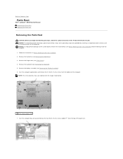
... the Hard Drive). 3. NOTE: The screw locations may vary slightly from the top of the computer. Remove the hard drive (see Hinge Cover). 4. Turn the computer upside down and remove the 14 M2.5 x 8-mm screws from the bottom of the palm rest. Turn the ... the computer. Remove the keyboard (see Removing the Display Assembly). 6. Back to the system board, remove the main battery (see Before Working Inside Your Computer) before working inside the computer. 1. NOTICE: To help prevent damage to Contents Page Palm Rest Dell™ Latitude™ D530 Service Manual Removing the Palm...
... the Hard Drive). 3. NOTE: The screw locations may vary slightly from the top of the computer. Remove the hard drive (see Hinge Cover). 4. Turn the computer upside down and remove the 14 M2.5 x 8-mm screws from the bottom of the palm rest. Turn the ... the computer. Remove the keyboard (see Removing the Display Assembly). 6. Back to the system board, remove the main battery (see Before Working Inside Your Computer) before working inside the computer. 1. NOTICE: To help prevent damage to Contents Page Palm Rest Dell™ Latitude™ D530 Service Manual Removing the Palm...
Service Manual
Page 43
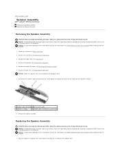
...main battery (see Removing the Keyboard). 5. Replacing the Speaker Assembly CAUTION: Before you begin the following procedure, follow the safety instructions in the Product Information Guide. Back to Contents Page Speaker Assembly Dell™ Latitude™ D530 Service Manual Removing the Speaker ... assembly 4 speaker cable connector on the screw holes for securing the assembly to them. 7. Remove the speaker assembly. Remove the hinge cover (see Removing the Palm Rest). Follow the instructions in Before You Begin. 2. Align the speaker assembly on system board 8. NOTICE: ...
...main battery (see Removing the Keyboard). 5. Replacing the Speaker Assembly CAUTION: Before you begin the following procedure, follow the safety instructions in the Product Information Guide. Back to Contents Page Speaker Assembly Dell™ Latitude™ D530 Service Manual Removing the Speaker ... assembly 4 speaker cable connector on the screw holes for securing the assembly to them. 7. Remove the speaker assembly. Remove the hinge cover (see Removing the Palm Rest). Follow the instructions in Before You Begin. 2. Align the speaker assembly on system board 8. NOTICE: ...
Service Manual
Page 45
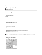
... on the bottom of the computer. Remove the modem (see Hinge Cover). 7. Remove the hinge cover (see Removing the Modem). 5. NOTE: It is not required but...assembly (see Memory Module). 4. Back to Contents Page System Board Assembly Dell™ Latitude™ D530 Service Manual Removing the System Board Assembly Replacing the System Board Assembly ...the instructions in the Product Information Guide. Remove the keyboard (see Removing the Display Assembly). 9. Remove the display assembly (see Removing the Keyboard). 8. Remove the processor (see Removing the Processor...
... on the bottom of the computer. Remove the modem (see Hinge Cover). 7. Remove the hinge cover (see Removing the Modem). 5. NOTE: It is not required but...assembly (see Memory Module). 4. Back to Contents Page System Board Assembly Dell™ Latitude™ D530 Service Manual Removing the System Board Assembly Replacing the System Board Assembly ...the instructions in the Product Information Guide. Remove the keyboard (see Removing the Display Assembly). 9. Remove the display assembly (see Removing the Keyboard). 8. Remove the processor (see Removing the Processor...


