System Information Guide
Page 12
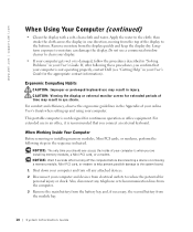
...that you are installing memory modules, a Mini PCI card, or a modem. Also, disconnect any attached devices. 2 Disconnect your computer. www.dell.com | support.dell.com When Using Your Computer (continued) • Clean the display with a soft, clean cloth and water. Remove moisture from the top of... periods of the display to reduce the potential for the appropriate contact information). This portable computer is when you connect an external keyboard. For extended use may result in your User's Guide. then stroke the cloth across the display in the sequence indicated. Apply...
...that you are installing memory modules, a Mini PCI card, or a modem. Also, disconnect any attached devices. 2 Disconnect your computer. www.dell.com | support.dell.com When Using Your Computer (continued) • Clean the display with a soft, clean cloth and water. Remove moisture from the top of... periods of the display to reduce the potential for the appropriate contact information). This portable computer is when you connect an external keyboard. For extended use may result in your User's Guide. then stroke the cloth across the display in the sequence indicated. Apply...

System Information Guide
Page 18
www.dell.com | support.dell.com About Your Computer Front View keyboard status lights touch pad touch pad buttons speakers display power button device status lights keyboard display latch 16 System Infor mation Guide
www.dell.com | support.dell.com About Your Computer Front View keyboard status lights touch pad touch pad buttons speakers display power button device status lights keyboard display latch 16 System Infor mation Guide
System Information Guide
Page 26
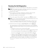
...174; logo appears, continue to run the Pre-boot System Assessment, a series of embedded diagnostics that perform initial testing on your system board, keyboard, hard drive, and display. • During the assessment, answer any key to a docking device (docked), undock it. The computer begins ... to the next test, press ; NOTE: If your computer cannot display a screen image, contact Dell (see the Windows desktop. www.dell.com | support.dell.com Running the Dell Diagnostics The Dell Diagnostics is connected to continue. 24 System Infor mation Guide NOTE: If you see "Getting Help"...
...174; logo appears, continue to run the Pre-boot System Assessment, a series of embedded diagnostics that perform initial testing on your system board, keyboard, hard drive, and display. • During the assessment, answer any key to a docking device (docked), undock it. The computer begins ... to the next test, press ; NOTE: If your computer cannot display a screen image, contact Dell (see the Windows desktop. www.dell.com | support.dell.com Running the Dell Diagnostics The Dell Diagnostics is connected to continue. 24 System Infor mation Guide NOTE: If you see "Getting Help"...
Service Manual
Page 1
Dell Latitude D500 Service Manual Dell™ Latitude™ D500 Service Manual Before You Begin Preparing to Work Inside the Computer Recommended Tools Computer Orientation Screw Identification Memory Module, Mini PCI Card, and Devices Memory Module Mini PCI Card Devices System Components Reserve Battery Hard Drive Keyboard Display Assembly and Display Latch Display Assembly Display Bezel Display Panel...
Dell Latitude D500 Service Manual Dell™ Latitude™ D500 Service Manual Before You Begin Preparing to Work Inside the Computer Recommended Tools Computer Orientation Screw Identification Memory Module, Mini PCI Card, and Devices Memory Module Mini PCI Card Devices System Components Reserve Battery Hard Drive Keyboard Display Assembly and Display Latch Display Assembly Display Bezel Display Panel...
Service Manual
Page 21
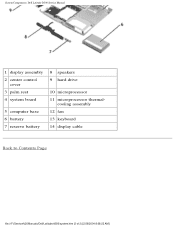
System Components: Dell Latitude D500 Service Manual 1 display assembly 2 center control cover 3 palm rest 4 system board 5 computer base 6 battery 7 reserve battery 8 speakers 9 hard drive 10 microprocessor 11 microprocessor thermal- cooling assembly 12 fan 13 keyboard 14 display cable Back to Contents Page file:///F|/Service%20Manuals/Dell/Latitude/d500/system.htm (2 of 2) [2/28/2004 8:08:22 AM]
System Components: Dell Latitude D500 Service Manual 1 display assembly 2 center control cover 3 palm rest 4 system board 5 computer base 6 battery 7 reserve battery 8 speakers 9 hard drive 10 microprocessor 11 microprocessor thermal- cooling assembly 12 fan 13 keyboard 14 display cable Back to Contents Page file:///F|/Service%20Manuals/Dell/Latitude/d500/system.htm (2 of 2) [2/28/2004 8:08:22 AM]

Service Manual
Page 28
... Contents Page Keyboard Dell™ Latitude™ D500 Service Manual CAUTION: Before performing the following procedures, read the safety instructions in your System Information Guide. NOTICE: To avoid electrostatic discharge, ground yourself by using a wrist grounding strap or by periodically touching an unpainted metal surface (such as the back panel) on the computer. 1. Keyboard: Dell Latitude D500 Service...
... Contents Page Keyboard Dell™ Latitude™ D500 Service Manual CAUTION: Before performing the following procedures, read the safety instructions in your System Information Guide. NOTICE: To avoid electrostatic discharge, ground yourself by using a wrist grounding strap or by periodically touching an unpainted metal surface (such as the back panel) on the computer. 1. Keyboard: Dell Latitude D500 Service...
Service Manual
Page 30
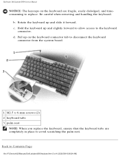
... to Contents Page file:///F|/Service%20Manuals/Dell/Latitude/d500/keyboard.htm (3 of 4) [2/28/2004 8:08:24 AM] Pull up and slide it forward. Rotate the keyboard up on the keyboard are completely in place to avoid scratching the palm rest. d. Back to the keyboard connector. Be careful when removing and handling the keyboard. Keyboard: Dell Latitude D500 Service Manual NOTICE: The keycaps...
... to Contents Page file:///F|/Service%20Manuals/Dell/Latitude/d500/keyboard.htm (3 of 4) [2/28/2004 8:08:24 AM] Pull up and slide it forward. Rotate the keyboard up on the keyboard are completely in place to avoid scratching the palm rest. d. Back to the keyboard connector. Be careful when removing and handling the keyboard. Keyboard: Dell Latitude D500 Service Manual NOTICE: The keycaps...
Service Manual
Page 32
... the display cable to the system board, and release the cable from the four cable-routing clips. file:///F|/Service%20Manuals/Dell/Latitude/d500/display.htm (1 of 9) [2/28/2004 8:08:26 AM] Remove the keyboard. 3. Loosen the captive screw that it does not open past this position. 4. NOTICE: To avoid electrostatic discharge, ground yourself by...
... the display cable to the system board, and release the cable from the four cable-routing clips. file:///F|/Service%20Manuals/Dell/Latitude/d500/display.htm (1 of 9) [2/28/2004 8:08:26 AM] Remove the keyboard. 3. Loosen the captive screw that it does not open past this position. 4. NOTICE: To avoid electrostatic discharge, ground yourself by...
Service Manual
Page 36
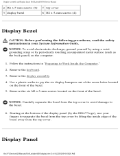
Remove the display assembly. 4. Remove the keyboard. 3. NOTICE: Carefully separate the bezel from the top cover to avoid damage to pry the six display bumpers out of the screw holes located on ... the six M2 x 5-mm screws located on the computer. 1. Starting at the bottom of the display panel (by the DELL™ logo), use your System Information Guide. Display Assembly and Display Latch: Dell Latitude D500 Service Manual 2 M2 x 5-mm screws (6) 3 display bezel 5 top cover 6 M2 x 5-mm screws (4) Display Bezel CAUTION: Before performing the following...
Remove the display assembly. 4. Remove the keyboard. 3. NOTICE: Carefully separate the bezel from the top cover to avoid damage to pry the six display bumpers out of the screw holes located on ... the six M2 x 5-mm screws located on the computer. 1. Starting at the bottom of the display panel (by the DELL™ logo), use your System Information Guide. Display Assembly and Display Latch: Dell Latitude D500 Service Manual 2 M2 x 5-mm screws (6) 3 display bezel 5 top cover 6 M2 x 5-mm screws (4) Display Bezel CAUTION: Before performing the following...

Service Manual
Page 37
... of 9) [2/28/2004 8:08:26 AM] file:///F|/Service%20Manuals/Dell/Latitude/d500/display.htm (6 of the top flex-cable connector, and pull the top flex-cable connector away from the display connector. 7. Remove the keyboard. 3. Remove the display bezel. 4. NOTICE: To avoid electrostatic discharge...2. Remove the two M2 x 5-mm screws from each side of the display cover. 6. Display Assembly and Display Latch: Dell Latitude D500 Service Manual CAUTION: Before performing the following procedures, read the safety instructions in "Preparing to disconnect the bottom flex-cable connector ...
... of 9) [2/28/2004 8:08:26 AM] file:///F|/Service%20Manuals/Dell/Latitude/d500/display.htm (6 of the top flex-cable connector, and pull the top flex-cable connector away from the display connector. 7. Remove the keyboard. 3. Remove the display bezel. 4. NOTICE: To avoid electrostatic discharge...2. Remove the two M2 x 5-mm screws from each side of the display cover. 6. Display Assembly and Display Latch: Dell Latitude D500 Service Manual CAUTION: Before performing the following procedures, read the safety instructions in "Preparing to disconnect the bottom flex-cable connector ...

Service Manual
Page 39
Remove the keyboard. 2. Remove the three M2 x 5-mm screws that the display bracket is upright when you replace the display latch. 1 top cover 2 M2 x 5-mm screws (3) file:///F|/Service%20Manuals/Dell/Latitude/d500/display.htm (8 of the top cover, and then remove the display latch. Remove the display bezel. 4. NOTE: Ensure that secure the display bracket to the top cover. 5. Display Assembly and Display Latch: Dell Latitude D500 Service Manual 1. Remove the display assembly. 3. Lift the display bracket out of 9) [2/28/2004 8:08:26 AM]
Remove the keyboard. 2. Remove the three M2 x 5-mm screws that the display bracket is upright when you replace the display latch. 1 top cover 2 M2 x 5-mm screws (3) file:///F|/Service%20Manuals/Dell/Latitude/d500/display.htm (8 of the top cover, and then remove the display latch. Remove the display bezel. 4. NOTE: Ensure that secure the display bracket to the top cover. 5. Display Assembly and Display Latch: Dell Latitude D500 Service Manual 1. Remove the display assembly. 3. Lift the display bracket out of 9) [2/28/2004 8:08:26 AM]

Service Manual
Page 41
... keyboard. file:///F|/Service%20Manuals/Dell/Latitude/d500/palmrest.htm (1 of the palm rest. NOTICE: You must remove the display assembly before you remove the palm rest; Remove the three M2 x 3-mm screws labeled "circle P" from the top of 4) [2/28/2004 8:08:27 AM] Follow the instructions in "Preparing to Contents Page Palm Rest Dell™ Latitude... an unpainted metal surface (such as the back panel) on the computer. 1. the display hinges pass through the back of the palm rest. 3. Palm Rest: Dell Latitude D500 Service Manual Back to Work Inside the Computer." 2.
... keyboard. file:///F|/Service%20Manuals/Dell/Latitude/d500/palmrest.htm (1 of the palm rest. NOTICE: You must remove the display assembly before you remove the palm rest; Remove the three M2 x 3-mm screws labeled "circle P" from the top of 4) [2/28/2004 8:08:27 AM] Follow the instructions in "Preparing to Contents Page Palm Rest Dell™ Latitude... an unpainted metal surface (such as the back panel) on the computer. 1. the display hinges pass through the back of the palm rest. 3. Palm Rest: Dell Latitude D500 Service Manual Back to Work Inside the Computer." 2.

Service Manual
Page 48
Remove the keyboard. 3. Pull straight up on the computer. 1. file:///F|/Service%20Manuals/Dell/Latitude/d500/fan.htm (1 of 3) [2/28/2004 8:08:28 AM] Follow the instructions in your System Information Guide. NOTICE: To avoid electrostatic ... Work Inside the Computer." 2. Remove the palm rest. 4. Remove the microprocessor thermal-cooling assembly. 5. Fan: Dell Latitude D500 Service Manual Back to Contents Page Fan Dell™ Latitude™ D500 Service Manual CAUTION: Before performing the following procedures, read the safety instructions in "Preparing to disconnect it from the...
Remove the keyboard. 3. Pull straight up on the computer. 1. file:///F|/Service%20Manuals/Dell/Latitude/d500/fan.htm (1 of 3) [2/28/2004 8:08:28 AM] Follow the instructions in your System Information Guide. NOTICE: To avoid electrostatic ... Work Inside the Computer." 2. Remove the palm rest. 4. Remove the microprocessor thermal-cooling assembly. 5. Fan: Dell Latitude D500 Service Manual Back to Contents Page Fan Dell™ Latitude™ D500 Service Manual CAUTION: Before performing the following procedures, read the safety instructions in "Preparing to disconnect it from the...

Service Manual
Page 51
file:///F|/Service%20Manuals/Dell/Latitude/d500/blue.htm (1 of 2) [2/28/2004 8:08:29 AM] NOTICE: To avoid electrostatic discharge, ground yourself by using a wrist grounding strap or by pulling it ... by periodically touching an unpainted metal surface (such as the back panel) on the computer. 1. Remove the keyboard. 3. Bluetooth™ Card: Dell Latitude D500 Service Manual Back to Contents Page Bluetooth™ Card Dell™ Latitude™ D500 Service Manual CAUTION: Before performing the following procedures, read the safety instructions in "Preparing to Work Inside the...
file:///F|/Service%20Manuals/Dell/Latitude/d500/blue.htm (1 of 2) [2/28/2004 8:08:29 AM] NOTICE: To avoid electrostatic discharge, ground yourself by using a wrist grounding strap or by pulling it ... by periodically touching an unpainted metal surface (such as the back panel) on the computer. 1. Remove the keyboard. 3. Bluetooth™ Card: Dell Latitude D500 Service Manual Back to Contents Page Bluetooth™ Card Dell™ Latitude™ D500 Service Manual CAUTION: Before performing the following procedures, read the safety instructions in "Preparing to Work Inside the...
Service Manual
Page 53
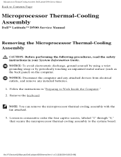
... the four captive screws, labeled "1" through "4," that secure the microprocessor thermal-cooling assembly to the system board. file:///F|/Service%20Manuals/Dell/Latitude/d500/thermal.htm (1 of 3) [2/28/2004 8:08:30 AM] NOTE: You can remove the microprocessor thermal-cooling assembly with the ...Assembly: Dell Latitude D500 Service Manual Back to Work Inside the Computer." 2. NOTICE: To avoid electrostatic discharge, ground yourself by using a wrist grounding strap or by periodically touching an unpainted metal surface (such as the back panel) on the computer. Remove the keyboard.
... the four captive screws, labeled "1" through "4," that secure the microprocessor thermal-cooling assembly to the system board. file:///F|/Service%20Manuals/Dell/Latitude/d500/thermal.htm (1 of 3) [2/28/2004 8:08:30 AM] NOTE: You can remove the microprocessor thermal-cooling assembly with the ...Assembly: Dell Latitude D500 Service Manual Back to Work Inside the Computer." 2. NOTICE: To avoid electrostatic discharge, ground yourself by using a wrist grounding strap or by periodically touching an unpainted metal surface (such as the back panel) on the computer. Remove the keyboard.
Service Manual
Page 56
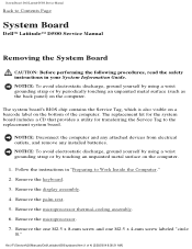
System Board: Dell Latitude D500 Service Manual Back to Contents Page System Board Dell™ Latitude™ D500 Service Manual Removing the System Board CAUTION: Before performing the following procedures, read the safety instructions in "Preparing to the ...." 2. file:///F|/Service%20Manuals/Dell/Latitude/d500/sysboard.htm (1 of the computer. NOTICE: To avoid electrostatic discharge, ground yourself by using a wrist grounding strap or by periodically touching an unpainted metal surface (such as the back panel) on the bottom of 4) [2/28/2004 8:08:31 AM] Remove the keyboard. 3.
System Board: Dell Latitude D500 Service Manual Back to Contents Page System Board Dell™ Latitude™ D500 Service Manual Removing the System Board CAUTION: Before performing the following procedures, read the safety instructions in "Preparing to the ...." 2. file:///F|/Service%20Manuals/Dell/Latitude/d500/sysboard.htm (1 of the computer. NOTICE: To avoid electrostatic discharge, ground yourself by using a wrist grounding strap or by periodically touching an unpainted metal surface (such as the back panel) on the bottom of 4) [2/28/2004 8:08:31 AM] Remove the keyboard. 3.

Service Manual
Page 60
... Guide. Follow the instructions in "Preparing to the microprocessor when turning the cam screw. 1. file:///F|/Service%20Manuals/Dell/Latitude/d500/cpu.htm (1 of the thermal pads. 3. NOTICE: To avoid electrostatic discharge, ground yourself by using a wrist...Dell Latitude D500 Service Manual Back to Contents Page Microprocessor Module Dell™ Latitude™ D500 Service Manual Removing the Microprocessor Module CAUTION: Before performing the following procedures, read the safety instructions in your skin reduce the heat transfer capability of 3) [2/28/2004 8:08:31 AM] Remove the keyboard...
... Guide. Follow the instructions in "Preparing to the microprocessor when turning the cam screw. 1. file:///F|/Service%20Manuals/Dell/Latitude/d500/cpu.htm (1 of the thermal pads. 3. NOTICE: To avoid electrostatic discharge, ground yourself by using a wrist...Dell Latitude D500 Service Manual Back to Contents Page Microprocessor Module Dell™ Latitude™ D500 Service Manual Removing the Microprocessor Module CAUTION: Before performing the following procedures, read the safety instructions in your skin reduce the heat transfer capability of 3) [2/28/2004 8:08:31 AM] Remove the keyboard...

Service Manual
Page 64
... reserve battery from the system board connector. Remove the keyboard. 3. Remove the speakers by periodically touching an unpainted metal surface (such as the back panel) on the computer. 1. Speakers: Dell Latitude D500 Service Manual Back to Contents Page Speakers Dell™ Latitude™ D500 Service Manual CAUTION: Before performing the following procedures, read... M2.5 x 4-mm screw from the speakers. 7. Remove the palm rest. 5. Remove the M2.5 x 8-mm screw from the speakers. 8. file:///F|/Service%20Manuals/Dell/Latitude/d500/speakers.htm (1 of the computer base. 9.
... reserve battery from the system board connector. Remove the keyboard. 3. Remove the speakers by periodically touching an unpainted metal surface (such as the back panel) on the computer. 1. Speakers: Dell Latitude D500 Service Manual Back to Contents Page Speakers Dell™ Latitude™ D500 Service Manual CAUTION: Before performing the following procedures, read... M2.5 x 4-mm screw from the speakers. 7. Remove the palm rest. 5. Remove the M2.5 x 8-mm screw from the speakers. 8. file:///F|/Service%20Manuals/Dell/Latitude/d500/speakers.htm (1 of the computer base. 9.

Service Manual
Page 66
... 3. Remove the keyboard. 4. NOTICE: To avoid electrostatic discharge, ground yourself by using a wrist grounding strap or by periodically touching an unpainted metal surface (such as the back panel) on the computer. 1. Remove the display assembly. 5. file:///F|/Service%20Manuals/Dell/Latitude/d500/latch.htm (1 of... 2) [2/28/2004 8:08:33 AM] Remove the speakers. 7. Base Latch: Dell Latitude D500 Service Manual Back to Work Inside the Computer." 2.
... 3. Remove the keyboard. 4. NOTICE: To avoid electrostatic discharge, ground yourself by using a wrist grounding strap or by periodically touching an unpainted metal surface (such as the back panel) on the computer. 1. Remove the display assembly. 5. file:///F|/Service%20Manuals/Dell/Latitude/d500/latch.htm (1 of... 2) [2/28/2004 8:08:33 AM] Remove the speakers. 7. Base Latch: Dell Latitude D500 Service Manual Back to Work Inside the Computer." 2.

Service Manual
Page 68
Remove the keyboard. 3. Remove the palm rest. 5. file:///F|/Service%20Manuals/Dell/Latitude/d500/modem.htm (1 of 3) [2/28/2004 8:08:34 AM] NOTICE: To avoid electrostatic discharge, ground yourself by using a wrist grounding ...Remove the display assembly. 4. Remove the M2 x 3-mm screw. Follow the instructions in your System Information Guide. Modem: Dell Latitude D500 Service Manual Back to Contents Page Modem Dell™ Latitude™ D500 Service Manual CAUTION: Before performing the following procedures, read the safety instructions in "Preparing to Work Inside the Computer." 2.
Remove the keyboard. 3. Remove the palm rest. 5. file:///F|/Service%20Manuals/Dell/Latitude/d500/modem.htm (1 of 3) [2/28/2004 8:08:34 AM] NOTICE: To avoid electrostatic discharge, ground yourself by using a wrist grounding ...Remove the display assembly. 4. Remove the M2 x 3-mm screw. Follow the instructions in your System Information Guide. Modem: Dell Latitude D500 Service Manual Back to Contents Page Modem Dell™ Latitude™ D500 Service Manual CAUTION: Before performing the following procedures, read the safety instructions in "Preparing to Work Inside the Computer." 2.


