Service Manual
Page 1
Dell Latitude D500 Service Manual Dell™ Latitude™ D500 Service Manual Before You Begin Preparing to Work Inside the Computer Recommended Tools Computer Orientation Screw Identification Memory Module, Mini PCI Card, ... Display Panel Display Latch Palm Rest Docking Doors Fan Bluetooth™ Card Microprocessor Thermal-Cooling Assembly System Board Microprocessor Module Flashing the BIOS Speakers Base Latch Modem Pin Assignments for I/O Connectors USB Connector Video Connector Parallel Connector file:///F|/Service%20Manuals/Dell/Latitude/d500/index.htm (1 of 2) [2/28/2004 8:08:10 AM]
Dell Latitude D500 Service Manual Dell™ Latitude™ D500 Service Manual Before You Begin Preparing to Work Inside the Computer Recommended Tools Computer Orientation Screw Identification Memory Module, Mini PCI Card, ... Display Panel Display Latch Palm Rest Docking Doors Fan Bluetooth™ Card Microprocessor Thermal-Cooling Assembly System Board Microprocessor Module Flashing the BIOS Speakers Base Latch Modem Pin Assignments for I/O Connectors USB Connector Video Connector Parallel Connector file:///F|/Service%20Manuals/Dell/Latitude/d500/index.htm (1 of 2) [2/28/2004 8:08:10 AM]
Service Manual
Page 5
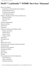
Remove the hard drive. Recommended Tools The procedures in this manual require the following tools: q #1 Phillips screwdriver q ¼-inch flat-blade screwdriver q Small plastic scribe q Flash BIOS update program floppy disk or CD file:///F|/Service%20Manuals/Dell/Latitude/d500/begin.htm (3 of 7) [2/28/2004 8:08:20 AM] Remove any installed memory modules, Mini PCI cards, and devices, including a second battery if one is installed. 12. Before You Begin: Dell Latitude D500 Service Manual 11.
Remove the hard drive. Recommended Tools The procedures in this manual require the following tools: q #1 Phillips screwdriver q ¼-inch flat-blade screwdriver q Small plastic scribe q Flash BIOS update program floppy disk or CD file:///F|/Service%20Manuals/Dell/Latitude/d500/begin.htm (3 of 7) [2/28/2004 8:08:20 AM] Remove any installed memory modules, Mini PCI cards, and devices, including a second battery if one is installed. 12. Before You Begin: Dell Latitude D500 Service Manual 11.
Service Manual
Page 56
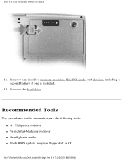
...on the computer. 1. Remove the microprocessor. 7. The system board's BIOS chip contains the Service Tag, which is also visible on a barcode label on the computer. System Board: Dell Latitude D500 Service Manual Back to Contents Page System Board Dell™ Latitude™ D500 Service Manual Removing the System Board CAUTION: Before performing the following ...2. Remove the palm rest. 5. Remove the keyboard. 3. Remove the one M2.5 x 8-mm screw and one M2.5 x 4-mm screw labeled "circle B." file:///F|/Service%20Manuals/Dell/Latitude/d500/sysboard.htm (1 of the computer.
...on the computer. 1. Remove the microprocessor. 7. The system board's BIOS chip contains the Service Tag, which is also visible on a barcode label on the computer. System Board: Dell Latitude D500 Service Manual Back to Contents Page System Board Dell™ Latitude™ D500 Service Manual Removing the System Board CAUTION: Before performing the following ...2. Remove the palm rest. 5. Remove the keyboard. 3. Remove the one M2.5 x 8-mm screw and one M2.5 x 4-mm screw labeled "circle B." file:///F|/Service%20Manuals/Dell/Latitude/d500/sysboard.htm (1 of the computer.
Service Manual
Page 59
Back to Contents Page file:///F|/Service%20Manuals/Dell/Latitude/d500/sysboard.htm (4 of the replacement system board. 3. System Board: Dell Latitude D500 Service Manual NOTE: After replacing the system board, enter the computer Service Tag into the appropriate drive. Insert the floppy disk or CD that appear on the screen. Follow the instructions that accompanied the replacement system board into the BIOS of 4) [2/28/2004 8:08:31 AM]
Back to Contents Page file:///F|/Service%20Manuals/Dell/Latitude/d500/sysboard.htm (4 of the replacement system board. 3. System Board: Dell Latitude D500 Service Manual NOTE: After replacing the system board, enter the computer Service Tag into the appropriate drive. Insert the floppy disk or CD that appear on the screen. Follow the instructions that accompanied the replacement system board into the BIOS of 4) [2/28/2004 8:08:31 AM]
Service Manual
Page 62
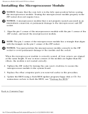
...position the microprocessor module correctly in the ZIF socket to avoid permanent damage to Contents Page file:///F|/Service%20Manuals/Dell/Latitude/d500/cpu.htm (3 of the microprocessor module has a triangle that is not properly seated can result in the...BIOS." NOTE: The pin-1 corner of 3) [2/28/2004 8:08:31 AM] Replace the other computer parts you removed earlier in the fully open position before seating the microprocessor module. NOTICE: A microprocessor module that aligns with the pin-1 corner of the module are aligned at the same height. Microprocessor Module: Dell Latitude D500...
...position the microprocessor module correctly in the ZIF socket to avoid permanent damage to Contents Page file:///F|/Service%20Manuals/Dell/Latitude/d500/cpu.htm (3 of the microprocessor module has a triangle that is not properly seated can result in the...BIOS." NOTE: The pin-1 corner of 3) [2/28/2004 8:08:31 AM] Replace the other computer parts you removed earlier in the fully open position before seating the microprocessor module. NOTICE: A microprocessor module that aligns with the pin-1 corner of the module are aligned at the same height. Microprocessor Module: Dell Latitude D500...
Service Manual
Page 63
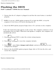
... reset the computer defaults. 5. NOTE: If you use a BIOS update program CD to flash the BIOS, set up the computer to save 6. to boot from the drive and restart the computer. Flashing the BIOS: Dell Latitude D500 Service Manual Back to Contents Page Flashing the BIOS Dell™ Latitude™ D500 Service Manual 1. Ensure that the AC adapter is plugged...
... reset the computer defaults. 5. NOTE: If you use a BIOS update program CD to flash the BIOS, set up the computer to save 6. to boot from the drive and restart the computer. Flashing the BIOS: Dell Latitude D500 Service Manual Back to Contents Page Flashing the BIOS Dell™ Latitude™ D500 Service Manual 1. Ensure that the AC adapter is plugged...


