Service Manual
Page 1
Dell Latitude D500 Service Manual Dell™ Latitude™ D500 Service Manual Before You Begin Preparing to Work Inside the Computer Recommended Tools Computer Orientation Screw Identification Memory Module, Mini PCI Card, and Devices Memory ... Assembly System Board Microprocessor Module Flashing the BIOS Speakers Base Latch Modem Pin Assignments for I/O Connectors USB Connector Video Connector Parallel Connector file:///F|/Service%20Manuals/Dell/Latitude/d500/index.htm (1 of 2) [2/28/2004 8:08:10 AM]
Dell Latitude D500 Service Manual Dell™ Latitude™ D500 Service Manual Before You Begin Preparing to Work Inside the Computer Recommended Tools Computer Orientation Screw Identification Memory Module, Mini PCI Card, and Devices Memory ... Assembly System Board Microprocessor Module Flashing the BIOS Speakers Base Latch Modem Pin Assignments for I/O Connectors USB Connector Video Connector Parallel Connector file:///F|/Service%20Manuals/Dell/Latitude/d500/index.htm (1 of 2) [2/28/2004 8:08:10 AM]
Service Manual
Page 2
... of 2) [2/28/2004 8:08:10 AM] A00 file:///F|/Service%20Manuals/Dell/Latitude/d500/index.htm (2 of Intel Corporation; Bluetooth is used in trademarks and trade names other than its own. Dell Computer Corporation disclaims any proprietary interest in this document to refer to either... Other trademarks and trade names may be used in this text: Dell, the DELL logo, and Latitude are registered trademarks of your computer. and is a trademark owned by Dell Computer Corporation under license. Dell Latitude D500 Service Manual S-Video TV-Out Connector Serial Connector Notes, Notices, and...
... of 2) [2/28/2004 8:08:10 AM] A00 file:///F|/Service%20Manuals/Dell/Latitude/d500/index.htm (2 of Intel Corporation; Bluetooth is used in trademarks and trade names other than its own. Dell Computer Corporation disclaims any proprietary interest in this document to refer to either... Other trademarks and trade names may be used in this text: Dell, the DELL logo, and Latitude are registered trademarks of your computer. and is a trademark owned by Dell Computer Corporation under license. Dell Latitude D500 Service Manual S-Video TV-Out Connector Serial Connector Notes, Notices, and...
Service Manual
Page 3
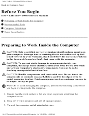
... your computer. Ensure that came with care. Turn off the computer and all open programs. 3. file:///F|/Service%20Manuals/Dell/Latitude/d500/begin working inside your computer, discharge static electricity from your body before you touch any work in the System Information... the safety instructions in progress and exit all attached devices. Before You Begin: Dell Latitude D500 Service Manual Back to Contents Page Before You Begin Dell™ Latitude™ D500 Service Manual Preparing to Work Inside the Computer Recommended Tools Computer Orientation Screw Identification ...
... your computer. Ensure that came with care. Turn off the computer and all open programs. 3. file:///F|/Service%20Manuals/Dell/Latitude/d500/begin working inside your computer, discharge static electricity from your body before you touch any work in the System Information... the safety instructions in progress and exit all attached devices. Before You Begin: Dell Latitude D500 Service Manual Back to Contents Page Before You Begin Dell™ Latitude™ D500 Service Manual Preparing to Work Inside the Computer Recommended Tools Computer Orientation Screw Identification ...
Service Manual
Page 4
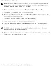
Before You Begin: Dell Latitude D500 Service Manual NOTE: Ensure that the computer is connected to 20 seconds and then disconnect any installed PC Cards from the bay. Close the display ... the computer is off and not in a power management mode. Remove any attached devices. 7. Slide and hold the power button for 4 seconds. 4. file:///F|/Service%20Manuals/Dell/Latitude/d500/begin.htm (2 of the computer, and then remove the battery from the PC Card slot. 9. To avoid possible damage to the system board, wait 10...
Before You Begin: Dell Latitude D500 Service Manual NOTE: Ensure that the computer is connected to 20 seconds and then disconnect any installed PC Cards from the bay. Close the display ... the computer is off and not in a power management mode. Remove any attached devices. 7. Slide and hold the power button for 4 seconds. 4. file:///F|/Service%20Manuals/Dell/Latitude/d500/begin.htm (2 of the computer, and then remove the battery from the PC Card slot. 9. To avoid possible damage to the system board, wait 10...
Service Manual
Page 5
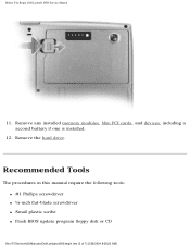
Before You Begin: Dell Latitude D500 Service Manual 11. Remove any installed memory modules, Mini PCI cards, and devices, including a second battery if one is installed. 12. Remove the hard drive. Recommended Tools The procedures in this manual require the following tools: q #1 Phillips screwdriver q ¼-inch flat-blade screwdriver q Small plastic scribe q Flash BIOS update program floppy disk or CD file:///F|/Service%20Manuals/Dell/Latitude/d500/begin.htm (3 of 7) [2/28/2004 8:08:20 AM]
Before You Begin: Dell Latitude D500 Service Manual 11. Remove any installed memory modules, Mini PCI cards, and devices, including a second battery if one is installed. 12. Remove the hard drive. Recommended Tools The procedures in this manual require the following tools: q #1 Phillips screwdriver q ¼-inch flat-blade screwdriver q Small plastic scribe q Flash BIOS update program floppy disk or CD file:///F|/Service%20Manuals/Dell/Latitude/d500/begin.htm (3 of 7) [2/28/2004 8:08:20 AM]
Service Manual
Page 6
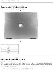
Before You Begin: Dell Latitude D500 Service Manual Computer Orientation 1 back 2 right 3 front 4 left Screw Identification When you are removing and replacing components, photocopy "Screw Identification" as a tool to lay out and keep track of screws and their sizes. The placemat provides the number of the screws. file:///F|/Service%20Manuals/Dell/Latitude/d500/begin.htm (4 of 7) [2/28/2004 8:08:20 AM]
Before You Begin: Dell Latitude D500 Service Manual Computer Orientation 1 back 2 right 3 front 4 left Screw Identification When you are removing and replacing components, photocopy "Screw Identification" as a tool to lay out and keep track of screws and their sizes. The placemat provides the number of the screws. file:///F|/Service%20Manuals/Dell/Latitude/d500/begin.htm (4 of 7) [2/28/2004 8:08:20 AM]
Service Manual
Page 10
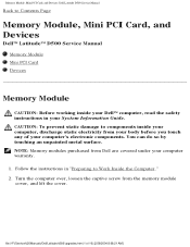
...the safety instructions in your computer warranty. 1. Turn the computer over, loosen the captive screw from Dell are covered under your System Information Guide. file:///F|/Service%20Manuals/Dell/Latitude/d500/upgrades.htm (1 of your body before you touch any of 10) [2/28/2004 8:08:21...touching an unpainted metal surface. Memory Module, Mini PCI Card, and Devices: Dell Latitude D500 Service Manual Back to Contents Page Memory Module, Mini PCI Card, and Devices Dell™ Latitude™ D500 Service Manual Memory Module Mini PCI Card Devices Memory Module CAUTION: Before working ...
...the safety instructions in your computer warranty. 1. Turn the computer over, loosen the captive screw from Dell are covered under your System Information Guide. file:///F|/Service%20Manuals/Dell/Latitude/d500/upgrades.htm (1 of your body before you touch any of 10) [2/28/2004 8:08:21...touching an unpainted metal surface. Memory Module, Mini PCI Card, and Devices: Dell Latitude D500 Service Manual Back to Contents Page Memory Module, Mini PCI Card, and Devices Dell™ Latitude™ D500 Service Manual Memory Module Mini PCI Card Devices Memory Module CAUTION: Before working ...
Service Manual
Page 11
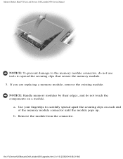
... apart the securing clips on a module. a. Remove the module from the connector. file:///F|/Service%20Manuals/Dell/Latitude/d500/upgrades.htm (2 of the memory module connector until the module pops up. b. Memory Module, Mini PCI Card, and Devices: Dell Latitude D500 Service Manual NOTICE: To prevent damage to the memory module connector, do not touch the components...
... apart the securing clips on a module. a. Remove the module from the connector. file:///F|/Service%20Manuals/Dell/Latitude/d500/upgrades.htm (2 of the memory module connector until the module pops up. b. Memory Module, Mini PCI Card, and Devices: Dell Latitude D500 Service Manual NOTICE: To prevent damage to the memory module connector, do not touch the components...
Service Manual
Page 12
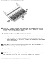
...Ground yourself and install the new memory module: a. Forcing the cover to close may damage your computer. Memory Module, Mini PCI Card, and Devices: Dell Latitude D500 Service Manual NOTICE: If you need to install memory modules in two connectors, install a memory module in the connector labeled "JDIM (Slot 1)" before... memory module cover is not installed properly, the computer does not boot. No error message indicates this failure. 5. file:///F|/Service%20Manuals/Dell/Latitude/d500/upgrades.htm (3 of the connector. If you do not feel a click. Replace the cover and screw.
...Ground yourself and install the new memory module: a. Forcing the cover to close may damage your computer. Memory Module, Mini PCI Card, and Devices: Dell Latitude D500 Service Manual NOTICE: If you need to install memory modules in two connectors, install a memory module in the connector labeled "JDIM (Slot 1)" before... memory module cover is not installed properly, the computer does not boot. No error message indicates this failure. 5. file:///F|/Service%20Manuals/Dell/Latitude/d500/upgrades.htm (3 of the connector. If you do not feel a click. Replace the cover and screw.
Service Manual
Page 13
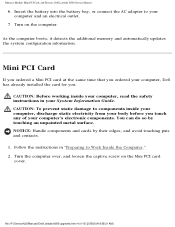
...] Follow the instructions in your computer's electronic components. CAUTION: Before working inside your computer, discharge static electricity from your body before you . file:///F|/Service%20Manuals/Dell/Latitude/d500/upgrades.htm (4 of your System Information Guide. Turn on the Mini PCI card cover. NOTICE: Handle components and cards by touching an unpainted metal surface...
...] Follow the instructions in your computer's electronic components. CAUTION: Before working inside your computer, discharge static electricity from your body before you . file:///F|/Service%20Manuals/Dell/Latitude/d500/upgrades.htm (4 of your System Information Guide. Turn on the Mini PCI card cover. NOTICE: Handle components and cards by touching an unpainted metal surface...
Service Manual
Page 14
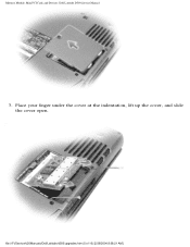
Memory Module, Mini PCI Card, and Devices: Dell Latitude D500 Service Manual 3. Place your finger under the cover at the indentation, lift up the cover, and slide the cover open. file:///F|/Service%20Manuals/Dell/Latitude/d500/upgrades.htm (5 of 10) [2/28/2004 8:08:21 AM]
Memory Module, Mini PCI Card, and Devices: Dell Latitude D500 Service Manual 3. Place your finger under the cover at the indentation, lift up the cover, and slide the cover open. file:///F|/Service%20Manuals/Dell/Latitude/d500/upgrades.htm (5 of 10) [2/28/2004 8:08:21 AM]
Service Manual
Page 15
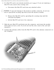
If you are replacing a Mini PCI card, remove the existing card: a. Memory Module, Mini PCI Card, and Devices: Dell Latitude D500 Service Manual 4. NOTICE: To prevent damage to the memory module connector, do not feel a click. Release the Mini PCI card by spreading the securing clips ... module. Slide the new Mini PCI card firmly into the connector, and rotate the module down until the card pops up slightly. file:///F|/Service%20Manuals/Dell/Latitude/d500/upgrades.htm (6 of its connector. 5. c. If a Mini PCI card is not already installed, go to step 5. b.
If you are replacing a Mini PCI card, remove the existing card: a. Memory Module, Mini PCI Card, and Devices: Dell Latitude D500 Service Manual 4. NOTICE: To prevent damage to the memory module connector, do not feel a click. Release the Mini PCI card by spreading the securing clips ... module. Slide the new Mini PCI card firmly into the connector, and rotate the module down until the card pops up slightly. file:///F|/Service%20Manuals/Dell/Latitude/d500/upgrades.htm (6 of its connector. 5. c. If a Mini PCI card is not already installed, go to step 5. b.
Service Manual
Page 16
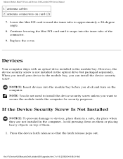
...you can install the device security screw. NOTE: You do not need to devices, place them . 1. Memory Module, Mini PCI Card, and Devices: Dell Latitude D500 Service Manual 1 antenna cables 2 antenna connectors on the computer. When you want to approximately a 20-degree angle. 8. Devices Your computer ships with an...that the latch release pops out. However, the device security screw is not installed in the module bay. file:///F|/Service%20Manuals/Dell/Latitude/d500/upgrades.htm (7 of them in a safe, dry place when they are not installed in the module bay, you dock and turn on ...
...you can install the device security screw. NOTE: You do not need to devices, place them . 1. Memory Module, Mini PCI Card, and Devices: Dell Latitude D500 Service Manual 1 antenna cables 2 antenna connectors on the computer. When you want to approximately a 20-degree angle. 8. Devices Your computer ships with an...that the latch release pops out. However, the device security screw is not installed in the module bay. file:///F|/Service%20Manuals/Dell/Latitude/d500/upgrades.htm (7 of them in a safe, dry place when they are not installed in the module bay, you dock and turn on ...
Service Manual
Page 17
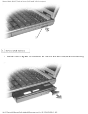
Memory Module, Mini PCI Card, and Devices: Dell Latitude D500 Service Manual 1 device latch release 2. Pull the device by the latch release to remove the device from the module bay. file:///F|/Service%20Manuals/Dell/Latitude/d500/upgrades.htm (8 of 10) [2/28/2004 8:08:21 AM]
Memory Module, Mini PCI Card, and Devices: Dell Latitude D500 Service Manual 1 device latch release 2. Pull the device by the latch release to remove the device from the module bay. file:///F|/Service%20Manuals/Dell/Latitude/d500/upgrades.htm (8 of 10) [2/28/2004 8:08:21 AM]
Service Manual
Page 18
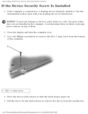
Memory Module, Mini PCI Card, and Devices: Dell Latitude D500 Service Manual If the Device Security Screw Is Installed 1. Press the device latch release so that came with your docking device for instructions. NOTICE: To ... them or placing heavy objects on top of the computer. 1 M2 x 3-mm screw 4. See the documentation that the latch release pops out. 5. file:///F|/Service%20Manuals/Dell/Latitude/d500/upgrades.htm (9 of 10) [2/28/2004 8:08:21 AM]
Memory Module, Mini PCI Card, and Devices: Dell Latitude D500 Service Manual If the Device Security Screw Is Installed 1. Press the device latch release so that came with your docking device for instructions. NOTICE: To ... them or placing heavy objects on top of the computer. 1 M2 x 3-mm screw 4. See the documentation that the latch release pops out. 5. file:///F|/Service%20Manuals/Dell/Latitude/d500/upgrades.htm (9 of 10) [2/28/2004 8:08:21 AM]
Service Manual
Page 20
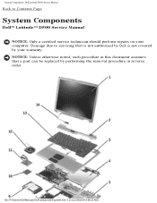
file:///F|/Service%20Manuals/Dell/Latitude/d500/system.htm (1 of 2) [2/28/2004 8:08:22 AM] NOTICE: Unless otherwise noted, each procedure in reverse order. System Components: Dell Latitude D500 Service Manual Back to servicing that is not authorized by Dell is not covered by performing the removal procedure in this document assumes that a part can be replaced by your computer. Damage due to Contents Page System Components Dell™ Latitude™ D500 Service Manual NOTICE: Only a certified service technician should perform repairs on your warranty.
file:///F|/Service%20Manuals/Dell/Latitude/d500/system.htm (1 of 2) [2/28/2004 8:08:22 AM] NOTICE: Unless otherwise noted, each procedure in reverse order. System Components: Dell Latitude D500 Service Manual Back to servicing that is not authorized by Dell is not covered by performing the removal procedure in this document assumes that a part can be replaced by your computer. Damage due to Contents Page System Components Dell™ Latitude™ D500 Service Manual NOTICE: Only a certified service technician should perform repairs on your warranty.
Service Manual
Page 21
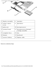
cooling assembly 12 fan 13 keyboard 14 display cable Back to Contents Page file:///F|/Service%20Manuals/Dell/Latitude/d500/system.htm (2 of 2) [2/28/2004 8:08:22 AM] System Components: Dell Latitude D500 Service Manual 1 display assembly 2 center control cover 3 palm rest 4 system board 5 computer base 6 battery 7 reserve battery 8 speakers 9 hard drive 10 microprocessor 11 microprocessor thermal-
cooling assembly 12 fan 13 keyboard 14 display cable Back to Contents Page file:///F|/Service%20Manuals/Dell/Latitude/d500/system.htm (2 of 2) [2/28/2004 8:08:22 AM] System Components: Dell Latitude D500 Service Manual 1 display assembly 2 center control cover 3 palm rest 4 system board 5 computer base 6 battery 7 reserve battery 8 speakers 9 hard drive 10 microprocessor 11 microprocessor thermal-
Service Manual
Page 22
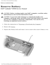
... Computer." 2. Remove the battery. 3. Follow the instructions in your computer's electronic components. file:///F|/Service%20Manuals/Dell/Latitude/d500/reserve.htm (1 of your System Information Guide. Reserve Battery: Dell Latitude D500 Service Manual Back to Contents Page Reserve Battery Dell™ Latitude™ D500 Service Manual CAUTION: Before working inside your computer, discharge static electricity from your body before you...
... Computer." 2. Remove the battery. 3. Follow the instructions in your computer's electronic components. file:///F|/Service%20Manuals/Dell/Latitude/d500/reserve.htm (1 of your System Information Guide. Reserve Battery: Dell Latitude D500 Service Manual Back to Contents Page Reserve Battery Dell™ Latitude™ D500 Service Manual CAUTION: Before working inside your computer, discharge static electricity from your body before you...
Service Manual
Page 23
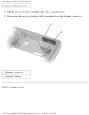
Reserve Battery: Dell Latitude D500 Service Manual 1 reserve battery cover 4. Pull the reserve battery straight out of 2) [2/28/2004 8:08:23 AM] Disconnect the reserve-battery cable connector from the battery connector. 1 battery connector 2 reserve battery Back to Contents Page file:///F|/Service%20Manuals/Dell/Latitude/d500/reserve.htm (2 of the computer base. 5.
Reserve Battery: Dell Latitude D500 Service Manual 1 reserve battery cover 4. Pull the reserve battery straight out of 2) [2/28/2004 8:08:23 AM] Disconnect the reserve-battery cable connector from the battery connector. 1 battery connector 2 reserve battery Back to Contents Page file:///F|/Service%20Manuals/Dell/Latitude/d500/reserve.htm (2 of the computer base. 5.
Service Manual
Page 24
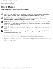
... the hard drive from sources other than Dell. 1. NOTICE: Hard drives are extremely fragile; even a slight bump can damage the drive. Follow the instructions in your computerbefore removing the hard drive. Hard Drive: Dell Latitude D500 Service Manual Back to Work Inside the ...Computer." 2. Turn the computer over. Use a standard #1 Phillips screwdriver to remove the M2.5 x 5-mm screw. file:///F|/Service%20Manuals/Dell/Latitude/d500/hdd.htm (1 of the hard drive.
... the hard drive from sources other than Dell. 1. NOTICE: Hard drives are extremely fragile; even a slight bump can damage the drive. Follow the instructions in your computerbefore removing the hard drive. Hard Drive: Dell Latitude D500 Service Manual Back to Work Inside the ...Computer." 2. Turn the computer over. Use a standard #1 Phillips screwdriver to remove the M2.5 x 5-mm screw. file:///F|/Service%20Manuals/Dell/Latitude/d500/hdd.htm (1 of the hard drive.


