
Service Manual
Page 4
... Cover 12 Removing the Memory Module Cover 12 Memory Modules 13 Removing the Memory Modules 13 Replacing the Memory Modules 13 Keyboard Assembly 14 Removing the Keyboard Assembly 14 Replacing the Keyboard Assembly 16 Microprocessor Module 18 Removing the Microprocessor Module 18 Replacing the Microprocessor Module 19 Display Assembly 20 Removing the Display...
... Cover 12 Removing the Memory Module Cover 12 Memory Modules 13 Removing the Memory Modules 13 Replacing the Memory Modules 13 Keyboard Assembly 14 Removing the Keyboard Assembly 14 Replacing the Keyboard Assembly 16 Microprocessor Module 18 Removing the Microprocessor Module 18 Replacing the Microprocessor Module 19 Display Assembly 20 Removing the Display...
Service Manual
Page 5
... Connector 5 Exploded View-Computer 10 Hard-Disk Drive Assembly Removal 11 Modular Bay Device Removal 12 Memory Module Removal 13 Removing the Keyboard Assembly Screws 14 Keyboard Assembly Removal 15 Keyboard and Track Stick Cables and Connectors 16 Microprocessor Module Removal 18 Display Assembly 20 14.1-Inch Display Assembly Bezel 21 Display Assembly...
... Connector 5 Exploded View-Computer 10 Hard-Disk Drive Assembly Removal 11 Modular Bay Device Removal 12 Memory Module Removal 13 Removing the Keyboard Assembly Screws 14 Keyboard Assembly Removal 15 Keyboard and Track Stick Cables and Connectors 16 Microprocessor Module Removal 18 Display Assembly 20 14.1-Inch Display Assembly Bezel 21 Display Assembly...

Service Manual
Page 11
Hard-Disk Drive Assembly: M3.0 x 5 (1 each) Keyboard Assembly: M2.5 x 10 (7 each) Display Assembly: M2.5 x 4 (3 each) Display Assembly Bezel: Rubber Screw Covers (4 each) Plastic Screw Covers (2 each) Display Assembly Bezel: M2.5 x 4 (6 each) 14.1-.... When you are removing and replacing components, photocopy the Table 1 placement mat as a tool to your system) Thermal Cooling Assembly and Exhaust Fan: M2.5 x 4 (2 each) 4 Dell Latitude CPt V/CPt S Series and CPx H/CPx J Series Service Manual
Hard-Disk Drive Assembly: M3.0 x 5 (1 each) Keyboard Assembly: M2.5 x 10 (7 each) Display Assembly: M2.5 x 4 (3 each) Display Assembly Bezel: Rubber Screw Covers (4 each) Plastic Screw Covers (2 each) Display Assembly Bezel: M2.5 x 4 (6 each) 14.1-.... When you are removing and replacing components, photocopy the Table 1 placement mat as a tool to your system) Thermal Cooling Assembly and Exhaust Fan: M2.5 x 4 (2 each) 4 Dell Latitude CPt V/CPt S Series and CPx H/CPx J Series Service Manual

Service Manual
Page 14
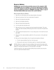
..., LP, ZPS 19 Reserve battery CUS, BTRY, RESERVE Euro-language specific KYBD, nn, iiii*, D-PTG, EMEA 10 keyboard Asian-language specific keyboard KYBD, nn, iiii*, D-PTG, APCC English (U.K.) KYBD, 88, UK, D-PTG, EMEA English (U.S.) KYBD, 87,... US, D-PTG, US English (International) KYBD, 87, US, INT, D-PTG, EMEA Keyboard screws (7) SCR, M2.5X10, PHH, LP, ZPS 9 * Substitute the number of keys for " nn" and the specific language ...14 14 16 16 14 16, 17 support.dell.com Dell Latitude CPt V/CPt S Series and CPx H/CPx J Series Service Manual 7
..., LP, ZPS 19 Reserve battery CUS, BTRY, RESERVE Euro-language specific KYBD, nn, iiii*, D-PTG, EMEA 10 keyboard Asian-language specific keyboard KYBD, nn, iiii*, D-PTG, APCC English (U.K.) KYBD, 88, UK, D-PTG, EMEA English (U.S.) KYBD, 87,... US, D-PTG, US English (International) KYBD, 87, US, INT, D-PTG, EMEA Keyboard screws (7) SCR, M2.5X10, PHH, LP, ZPS 9 * Substitute the number of keys for " nn" and the specific language ...14 14 16 16 14 16, 17 support.dell.com Dell Latitude CPt V/CPt S Series and CPx H/CPx J Series Service Manual 7

Service Manual
Page 17
display assembly keyboard palmrest assembly hard-disk drive internal modem (may not apply to your system) system board main battery case plug for modem bottom case assembly modular bay device The following subsections provide instructions for removing and replacing field-replaceable parts and assemblies. 10 Dell Latitude CPt V/CPt S Series and CPx H/CPx J Series Service Manual
display assembly keyboard palmrest assembly hard-disk drive internal modem (may not apply to your system) system board main battery case plug for modem bottom case assembly modular bay device The following subsections provide instructions for removing and replacing field-replaceable parts and assemblies. 10 Dell Latitude CPt V/CPt S Series and CPx H/CPx J Series Service Manual

Service Manual
Page 22
Turn the computer right-side up and open the display. 5. support.dell.com Dell Latitude CPt V/CPt S Series and CPx H/CPx J Series Service Manual 15 Lift the keyboard out of blank key palmrest 6. Rest the key face of the keyboard on the left edge of the keyboard. 3. Remove the seven 10-mm screws, labeled with a " circle K," that secure the...
Turn the computer right-side up and open the display. 5. support.dell.com Dell Latitude CPt V/CPt S Series and CPx H/CPx J Series Service Manual 15 Lift the keyboard out of blank key palmrest 6. Rest the key face of the keyboard on the left edge of the keyboard. 3. Remove the seven 10-mm screws, labeled with a " circle K," that secure the...

Service Manual
Page 23
... left side of the computer with the keys face down when you insert the cable into the keyboard ZIF interface connector. 16 Dell Latitude CPt V/CPt S Series and CPx H/CPx J Series Service Manual Remove the keyboard assembly. 1. Connect the keyboard cable to the ZIF connector. Ensure that the contact side of this cable is face down (see...
... left side of the computer with the keys face down when you insert the cable into the keyboard ZIF interface connector. 16 Dell Latitude CPt V/CPt S Series and CPx H/CPx J Series Service Manual Remove the keyboard assembly. 1. Connect the keyboard cable to the ZIF connector. Ensure that the contact side of this cable is face down (see...

Service Manual
Page 24
... of the computer and then work inward to the center. Ensure that the keyboard is correctly installed. Check that the track stick and keyboard cables are not twisted as you lower the keyboard into place. support.dell.com Dell Latitude CPt V/CPt S Series and CPx H/CPx J Series Service Manual 17 Start by installing the outermost screws on the...
... of the computer and then work inward to the center. Ensure that the keyboard is correctly installed. Check that the track stick and keyboard cables are not twisted as you lower the keyboard into place. support.dell.com Dell Latitude CPt V/CPt S Series and CPx H/CPx J Series Service Manual 17 Start by installing the outermost screws on the...

Service Manual
Page 25
... module (see Figure 12). 4. 3-mm screws (2) microprocessor shield 4-mm screw (1) shield brace (may not apply to the microprocessor module. 18 Dell Latitude CPt V/CPt S Series and CPx H/CPx J Series Service Manual Remove the keyboard assembly. 3. Remove the main battery and secondary battery (if present). 2. Remove the two 3-mm screws on the microprocessor board (2) microprocessor module...
... module (see Figure 12). 4. 3-mm screws (2) microprocessor shield 4-mm screw (1) shield brace (may not apply to the microprocessor module. 18 Dell Latitude CPt V/CPt S Series and CPx H/CPx J Series Service Manual Remove the keyboard assembly. 3. Remove the main battery and secondary battery (if present). 2. Remove the two 3-mm screws on the microprocessor board (2) microprocessor module...

Service Manual
Page 27
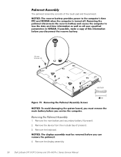
... the seam from the back of the computer (see Figure 13). NOTE: Always remove and replace the LCD panel as a complete assembly. 20 Dell Latitude CPt V/CPt S Series and CPx H/CPx J Series Service Manual Close the display and remove the three 4-mm screws, labeled with a " circle D," from the snap tabs on the system board...). 4. Remove the main battery and secondary battery (if present). 2. Open the display and disconnect the LCD flex cable from the bottom case assembly. Remove the keyboard. 3.
... the seam from the back of the computer (see Figure 13). NOTE: Always remove and replace the LCD panel as a complete assembly. 20 Dell Latitude CPt V/CPt S Series and CPx H/CPx J Series Service Manual Close the display and remove the three 4-mm screws, labeled with a " circle D," from the snap tabs on the system board...). 4. Remove the main battery and secondary battery (if present). 2. Open the display and disconnect the LCD flex cable from the bottom case assembly. Remove the keyboard. 3.
Service Manual
Page 37
The palmrest assembly consists of the touch pad and the palmrest. 20-mm screws (5) M2.5x20 1. Remove the main battery and secondary battery (if present). 2. Remove the keyboard. 4. Remove the display assembly. 30 Dell Latitude CPt V/CPt S Series and CPx H/CPx J Series Service Manual Remove the device from the modular bay (if present). 3.
The palmrest assembly consists of the touch pad and the palmrest. 20-mm screws (5) M2.5x20 1. Remove the main battery and secondary battery (if present). 2. Remove the keyboard. 4. Remove the display assembly. 30 Dell Latitude CPt V/CPt S Series and CPx H/CPx J Series Service Manual Remove the device from the modular bay (if present). 3.
Service Manual
Page 39
... the reserve battery EMI spring clip before securing the two 4-mm palmrest bracket screws. 32 Dell Latitude CPt V/CPt S Series and CPx H/CPx J Series Service Manual Remove the remnants of the foam pad from the foam pad. Remove the keyboard assembly. 4. This may loosen the reserve battery EMI spring clip which is secured to twist...
... the reserve battery EMI spring clip before securing the two 4-mm palmrest bracket screws. 32 Dell Latitude CPt V/CPt S Series and CPx H/CPx J Series Service Manual Remove the remnants of the foam pad from the foam pad. Remove the keyboard assembly. 4. This may loosen the reserve battery EMI spring clip which is secured to twist...

Service Manual
Page 40
... in the bottom case assembly. 2. Remove the 10-mm screw and washer securing the modem assembly (see Figure 21). 1. support.dell.com Dell Latitude CPt V/CPt S Series and CPx H/CPx J Series Service Manual 33 The modem (if present) must be removed before the main system board can be removed (see Figure 21... modem assembly is optional. Replace the internal modem 10-mm screw and washer (see Figure 21). Remove the palmrest assembly. 5. Remove the keyboard assembly. 3. Remove the display assembly. 4. Press the RJ11 connector of the modem assembly into the system board connector. 3.
... in the bottom case assembly. 2. Remove the 10-mm screw and washer securing the modem assembly (see Figure 21). 1. support.dell.com Dell Latitude CPt V/CPt S Series and CPx H/CPx J Series Service Manual 33 The modem (if present) must be removed before the main system board can be removed (see Figure 21... modem assembly is optional. Replace the internal modem 10-mm screw and washer (see Figure 21). Remove the palmrest assembly. 5. Remove the keyboard assembly. 3. Remove the display assembly. 4. Press the RJ11 connector of the modem assembly into the system board connector. 3.
Service Manual
Page 41
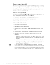
... the microprocessor module. 7. Remove the two screws securing the system board assembly (see Figure 22). 34 Dell Latitude CPt V/CPt S Series and CPx H/CPx J Series Service Manual Remove the device from the modular bay (if present). 3. Remove the keyboard assembly. 4. Locate and remove the 4-mm screw with washer that the PC Card ejectors do not...
... the microprocessor module. 7. Remove the two screws securing the system board assembly (see Figure 22). 34 Dell Latitude CPt V/CPt S Series and CPx H/CPx J Series Service Manual Remove the device from the modular bay (if present). 3. Remove the keyboard assembly. 4. Locate and remove the 4-mm screw with washer that the PC Card ejectors do not...
Service Manual
Page 42
...(system without modem) M2.5x4 M2.5x10 10. Replace the system board mounting screws. 4. Replace the microprocessor, the palmrest assembly, the display assembly and the keyboard assembly. NOTE: After replacing the system board assembly, be sure to the replacement system board assembly. 5. Remove the modem (if present). 11. Install the ... service tag number into the appropriate drive, and turn on the computer. Lift the system board assembly out of the replacement system board assembly. support.dell.com Dell Latitude CPt V/CPt S Series and CPx H/CPx J Series Service Manual 35
...(system without modem) M2.5x4 M2.5x10 10. Replace the system board mounting screws. 4. Replace the microprocessor, the palmrest assembly, the display assembly and the keyboard assembly. NOTE: After replacing the system board assembly, be sure to the replacement system board assembly. 5. Remove the modem (if present). 11. Install the ... service tag number into the appropriate drive, and turn on the computer. Lift the system board assembly out of the replacement system board assembly. support.dell.com Dell Latitude CPt V/CPt S Series and CPx H/CPx J Series Service Manual 35
Service Manual
Page 43
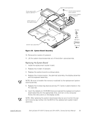
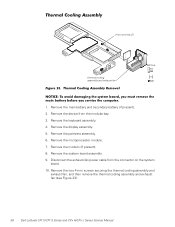
Remove the keyboard assembly. 4. Remove the display assembly. 5. 4-mm screws (2) thermal cooling assembly and exhaust fan M2.5x4 1. Remove the main battery and secondary battery (if present). 2. Remove ... screws securing the thermal cooling assembly and exhaust fan, and then remove the thermal cooling assembly and exhaust fan (see Figure 23). 36 Dell Latitude CPt V/CPt S Series and CPx H/CPx J Series Service Manual Remove the device from the connector on the system board. 10. Remove the palmrest assembly. 6. Remove the modem (if present...
Remove the keyboard assembly. 4. Remove the display assembly. 5. 4-mm screws (2) thermal cooling assembly and exhaust fan M2.5x4 1. Remove the main battery and secondary battery (if present). 2. Remove ... screws securing the thermal cooling assembly and exhaust fan, and then remove the thermal cooling assembly and exhaust fan (see Figure 23). 36 Dell Latitude CPt V/CPt S Series and CPx H/CPx J Series Service Manual Remove the device from the connector on the system board. 10. Remove the palmrest assembly. 6. Remove the modem (if present...
Service Manual
Page 44
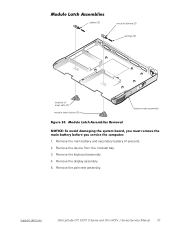
sliders (2) module latches (2) springs (2) location of snap tabs (2) module latch button (2) bottom case assembly 1. Remove the display assembly. 5. Remove the device from the modular bay. 3. Remove the keyboard assembly. 4. Remove the main battery and secondary battery (if present). 2. support.dell.com Dell Latitude CPt V/CPt S Series and CPx H/CPx J Series Service Manual 37 Remove the palmrest assembly.
sliders (2) module latches (2) springs (2) location of snap tabs (2) module latch button (2) bottom case assembly 1. Remove the display assembly. 5. Remove the device from the modular bay. 3. Remove the keyboard assembly. 4. Remove the main battery and secondary battery (if present). 2. support.dell.com Dell Latitude CPt V/CPt S Series and CPx H/CPx J Series Service Manual 37 Remove the palmrest assembly.
Service Manual
Page 47
hard-disk drive assembly removal, 11 reserve battery removal, 32 inverter, 12.1-inch LCD panel removal, 26 replacement, 27 keyboard assembly removal, 15 memory module removal, 13 memory module cover removal, 12 microprocessor module removal, 18 modular bay devices removal, 12 module latch assemblies removal, ...-120 drive removal, 12 system board assembly removal, 18 thermal cooling assembly removal, 36 tools, 2 travel module removal, 12 ZIF connectors, 5 palmrest assembly removal, 30 2 Dell Latitude CPt V/CPt S Series and CPx H/Cpx J Series Service Manual
hard-disk drive assembly removal, 11 reserve battery removal, 32 inverter, 12.1-inch LCD panel removal, 26 replacement, 27 keyboard assembly removal, 15 memory module removal, 13 memory module cover removal, 12 microprocessor module removal, 18 modular bay devices removal, 12 module latch assemblies removal, ...-120 drive removal, 12 system board assembly removal, 18 thermal cooling assembly removal, 36 tools, 2 travel module removal, 12 ZIF connectors, 5 palmrest assembly removal, 30 2 Dell Latitude CPt V/CPt S Series and CPx H/Cpx J Series Service Manual
System Information Guide (multilanguage: English, Japanese, Chinese-Traditional, Chinese-Simplified, Korean, Thai)
Page 13
...weight of your legs is damaged, follow the procedures described in "Troubleshooting Your Computer" in a neutral, comfortable position while using the keyboard, touch pad or external mouse. • Always use , it can be cleaned using an external monitor with your computer, set the... guidelines when setting up and using your computer: • Position your work activities. Preliminary 1/25/00 Dell Latitude System Information 1-9 (Rev. 11/3/98) FILE LOCATION: \\Pd-xuzhan\d\FrameMaker\Dell\sndmm003\en\999CCA00en.fm • If the touch pad becomes smudged from your chair seat.
...weight of your legs is damaged, follow the procedures described in "Troubleshooting Your Computer" in a neutral, comfortable position while using the keyboard, touch pad or external mouse. • Always use , it can be cleaned using an external monitor with your computer, set the... guidelines when setting up and using your computer: • Position your work activities. Preliminary 1/25/00 Dell Latitude System Information 1-9 (Rev. 11/3/98) FILE LOCATION: \\Pd-xuzhan\d\FrameMaker\Dell\sndmm003\en\999CCA00en.fm • If the touch pad becomes smudged from your chair seat.
System Information Guide (multilanguage: English, Japanese, Chinese-Traditional, Chinese-Simplified, Korean, Thai)
Page 15
... antistatic packaging, be sure to discharge static electricity from the antistatic packing material until you are ready to install the component. Preliminary 1/25/00 Dell Latitude System Information 1-11 If the modular bay contains a battery, go to an electrical outlet and preserve your body. • When transporting a ...one of these ways: • Use suspend mode Place the computer in suspend mode by touching an unpainted metal surface on an external keyboard if the External Hot Key option is enabled in a static-safe area. If the only battery in the computer is in the battery...
... antistatic packaging, be sure to discharge static electricity from the antistatic packing material until you are ready to install the component. Preliminary 1/25/00 Dell Latitude System Information 1-11 If the modular bay contains a battery, go to an electrical outlet and preserve your body. • When transporting a ...one of these ways: • Use suspend mode Place the computer in suspend mode by touching an unpainted metal surface on an external keyboard if the External Hot Key option is enabled in a static-safe area. If the only battery in the computer is in the battery...


