Service Manual
Page 9
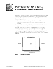
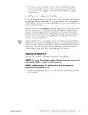
... manual, the locations or directions relative to the bottom case should never be replaced by performing the removal procedure in your Dell Latitude portable computer. The angle of computer support.dell.com Dell Latitude CPt V-Series/CPx H-Series Service Manual 1 This manual provides instructions for removing and replacing field-replaceable components, assemblies, and subassemblies in reverse...
... manual, the locations or directions relative to the bottom case should never be replaced by performing the removal procedure in your Dell Latitude portable computer. The angle of computer support.dell.com Dell Latitude CPt V-Series/CPx H-Series Service Manual 1 This manual provides instructions for removing and replacing field-replaceable components, assemblies, and subassemblies in reverse...
Service Manual
Page 10
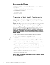
... computer is turned off the computer and any telephone or telecommunications lines from the computer. 7. Also disconnect any attached peripherals. Save any installed PC Cards. 2 Dell Latitude CPt V-Series/CPx H-Series Service Manual NOTE: Make sure the computer is docked in a C/Dock Family Expansion Station or C/Port Family Advanced Port Replicator (APR), undock...
... computer is turned off the computer and any telephone or telecommunications lines from the computer. 7. Also disconnect any attached peripherals. Save any installed PC Cards. 2 Dell Latitude CPt V-Series/CPx H-Series Service Manual NOTE: Make sure the computer is docked in a C/Dock Family Expansion Station or C/Port Family Advanced Port Replicator (APR), undock...
Service Manual
Page 11
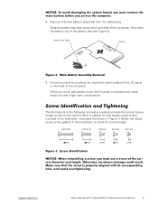
... on the back of the computer. Then slide the battery out of the computer. M2.5x20 M2.5x10 M3.0x5 M2.5x4 M2.0x3 support.dell.com Dell Latitude CPt V-Series/CPx H-Series Service Manual 3 Ground yourself by touching the unpainted metal surface of the screw's label. The illustrations in Figure 3. Examples are shown...
... on the back of the computer. Then slide the battery out of the computer. M2.5x20 M2.5x10 M3.0x5 M2.5x4 M2.0x3 support.dell.com Dell Latitude CPt V-Series/CPx H-Series Service Manual 3 Ground yourself by touching the unpainted metal surface of the screw's label. The illustrations in Figure 3. Examples are shown...

Service Manual
Page 12
...: M3 x 3 (3 each) Palmrest Assembly: M2.5 x 20 (5 each) System Board: M2.5 x 4 (2 each) Microprocessor Shield: 3 captive and 2 removable screws M2 x 3 (2 each) TCA and Exhaust Fan: M2.5 x 4 (2 each) 4 Dell Latitude CPt V-Series/CPx H-Series Service Manual
...: M3 x 3 (3 each) Palmrest Assembly: M2.5 x 20 (5 each) System Board: M2.5 x 4 (2 each) Microprocessor Shield: 3 captive and 2 removable screws M2 x 3 (2 each) TCA and Exhaust Fan: M2.5 x 4 (2 each) 4 Dell Latitude CPt V-Series/CPx H-Series Service Manual
Service Manual
Page 13
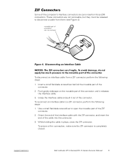
... released to a ZIF connector, perform the following steps: 1. movable part of connector (do not remove) To disconnect an interface cable from them (see Figure 4). support.dell.com Dell Latitude CPt V-Series/CPx H-Series Service Manual 5
... released to a ZIF connector, perform the following steps: 1. movable part of connector (do not remove) To disconnect an interface cable from them (see Figure 4). support.dell.com Dell Latitude CPt V-Series/CPx H-Series Service Manual 5
Service Manual
Page 14
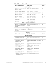
..., NBK, 24X, TSHBA PWA, INTERCONN, CD/DVD, OMAHA ASSY, BTM/BZL, CD, 24X, TSHBA ASSY, HSG, PLSTC, CD/DVD, OMHA LBL, CD, MEDIA BAY, TSHB 6 Dell Latitude CPt V-Series/CPx H-Series Service Manual The subsections that follow Table 2 provide instructions for the computer. Some parts may only be available as part of a service...
..., NBK, 24X, TSHBA PWA, INTERCONN, CD/DVD, OMAHA ASSY, BTM/BZL, CD, 24X, TSHBA ASSY, HSG, PLSTC, CD/DVD, OMHA LBL, CD, MEDIA BAY, TSHB 6 Dell Latitude CPt V-Series/CPx H-Series Service Manual The subsections that follow Table 2 provide instructions for the computer. Some parts may only be available as part of a service...
Service Manual
Page 15
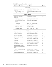
support.dell.com Dell Latitude CPt V-Series/CPx H-Series Service Manual 7 Diskette drive service kit SVC, SUBASSY, FD, F3, INT/EXT, 7 CRNA Diskette drive subassembly SUBASSY, FD, F3, INT/EXT, CRNA ...
support.dell.com Dell Latitude CPt V-Series/CPx H-Series Service Manual 7 Diskette drive service kit SVC, SUBASSY, FD, F3, INT/EXT, 7 CRNA Diskette drive subassembly SUBASSY, FD, F3, INT/EXT, CRNA ...
Service Manual
Page 16
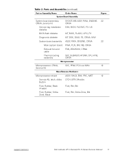
..., D-PTG Keyboard, Swiss KYBD, 88, SWI, D-PTG Keyboard, Thai KYBD, 87, THAI, D-PTG Keyboard, English (U.K.) KYBD, 88, UK, D-PTG Keyboard, English (U.S.) KYBD, 87, DOM, D-PTG 8 Dell Latitude CPt V-Series/CPx H-Series Service Manual
..., D-PTG Keyboard, Swiss KYBD, 88, SWI, D-PTG Keyboard, Thai KYBD, 87, THAI, D-PTG Keyboard, English (U.K.) KYBD, 88, UK, D-PTG Keyboard, English (U.S.) KYBD, 87, DOM, D-PTG 8 Dell Latitude CPt V-Series/CPx H-Series Service Manual
Service Manual
Page 17
support.dell.com Dell Latitude CPt V-Series/CPx H-Series Service Manual 9 Display top-cover service kit, 14.1-inch display 14.1-inch display top cover 12.1-inch display top cover 14.1-inch ...
support.dell.com Dell Latitude CPt V-Series/CPx H-Series Service Manual 9 Display top-cover service kit, 14.1-inch display 14.1-inch display top cover 12.1-inch display top cover 14.1-inch ...
Service Manual
Page 18
..., ZPS SCR, M2.5X20, PHH, LP, ZPS SCR, M2.5X4, PHH, LP, ZPS 13 14 15 15, 17 13 14 9 6 12 23 19 22 10 Dell Latitude CPt V-Series/CPx H-Series Service Manual
..., ZPS SCR, M2.5X20, PHH, LP, ZPS SCR, M2.5X4, PHH, LP, ZPS 13 14 15 15, 17 13 14 9 6 12 23 19 22 10 Dell Latitude CPt V-Series/CPx H-Series Service Manual
Service Manual
Page 19
... Kit, latch, slider, LTCH, BTN, Module Button Foot, Rubber, Black (4 each) Foot, Rbr, Blk Foot, Rubber, Strike Zone, Black Foot, Rbr, Strike Zone, Blk support.dell.com Dell Latitude CPt V-Series/CPx H-Series Service Manual 11
... Kit, latch, slider, LTCH, BTN, Module Button Foot, Rubber, Black (4 each) Foot, Rbr, Blk Foot, Rubber, Strike Zone, Black Foot, Rbr, Strike Zone, Blk support.dell.com Dell Latitude CPt V-Series/CPx H-Series Service Manual 11

Service Manual
Page 20
display assembly keyboard palmrest assembly hard-disk drive system board main battery bottom case assembly modular bay device The following subsections provide instructions for removing and replacing field-replaceable parts and assemblies. 12 Dell Latitude CPt V-Series/CPx H-Series Service Manual
display assembly keyboard palmrest assembly hard-disk drive system board main battery bottom case assembly modular bay device The following subsections provide instructions for removing and replacing field-replaceable parts and assemblies. 12 Dell Latitude CPt V-Series/CPx H-Series Service Manual
Service Manual
Page 21
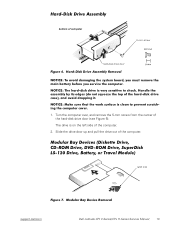
The drive is on the left side of computer 5-mm screw M3.0x5 hard-disk drive door 1. bottom of the computer. 2. Slide the drive door up and pull the drive out of the hard-disk drive door (see Figure 6). latch lock support.dell.com Dell Latitude CPt V-Series/CPx H-Series Service Manual 13 Turn the computer over, and remove the 5-mm screw from the center of the computer.
The drive is on the left side of computer 5-mm screw M3.0x5 hard-disk drive door 1. bottom of the computer. 2. Slide the drive door up and pull the drive out of the hard-disk drive door (see Figure 6). latch lock support.dell.com Dell Latitude CPt V-Series/CPx H-Series Service Manual 13 Turn the computer over, and remove the 5-mm screw from the center of the computer.

Service Manual
Page 22
Remove the memory module cover. 14 Dell Latitude CPt V-Series/CPx H-Series Service Manual 1. Push the module latch toward the unlock icon. Keep holding the latch open while pulling the device out of the ...
Remove the memory module cover. 14 Dell Latitude CPt V-Series/CPx H-Series Service Manual 1. Push the module latch toward the unlock icon. Keep holding the latch open while pulling the device out of the ...
Service Manual
Page 23
... into their sockets, in the center of the memory module snaps into the tabs, remove the memory module and reinstall it in the socket. support.dell.com Dell Latitude CPt V-Series/CPx H-Series Service Manual 15 If you do not hear a click as each end of the memory module socket. NOTE: 192-MB memory...
... into their sockets, in the center of the memory module snaps into the tabs, remove the memory module and reinstall it in the socket. support.dell.com Dell Latitude CPt V-Series/CPx H-Series Service Manual 15 If you do not hear a click as each end of the memory module socket. NOTE: 192-MB memory...

Service Manual
Page 24
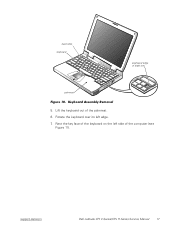
Remove the seven 10-mm screws, labeled with a "circle K," that secure the keyboard to the computer (see Figure 10), and lift the right edge of the blank key (see Figure 9). 3. Turn the computer right-side up and open the display. 4. 10-mm screws (7) M2.5x10 2. Release the keyboard from the palmrest assembly by inserting a small flat-blade screwdriver under the edge of the keyboard. 16 Dell Latitude CPt V-Series/CPx H-Series Service Manual
Remove the seven 10-mm screws, labeled with a "circle K," that secure the keyboard to the computer (see Figure 10), and lift the right edge of the blank key (see Figure 9). 3. Turn the computer right-side up and open the display. 4. 10-mm screws (7) M2.5x10 2. Release the keyboard from the palmrest assembly by inserting a small flat-blade screwdriver under the edge of the keyboard. 16 Dell Latitude CPt V-Series/CPx H-Series Service Manual
Service Manual
Page 25
Lift the keyboard out of blank key palmrest 5. Rotate the keyboard over its left side of the keyboard on the left edge. 7. track stick keyboard scalloped edge of the palmrest. 6. support.dell.com Dell Latitude CPt V-Series/CPx H-Series Service Manual 17 Rest the key face of the computer (see Figure 11).
Lift the keyboard out of blank key palmrest 5. Rotate the keyboard over its left side of the keyboard on the left edge. 7. track stick keyboard scalloped edge of the palmrest. 6. support.dell.com Dell Latitude CPt V-Series/CPx H-Series Service Manual 17 Rest the key face of the computer (see Figure 11).
Service Manual
Page 26
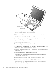
... are not twisted as you insert the cable into the ZIF connector. 3. Carefully turn the keyboard over and fit the keyboard into the palmrest. 18 Dell Latitude CPt V-Series/CPx H-Series Service Manual Remove the keyboard assembly. To replace the keyboard assembly, perform the following steps. 1. Disconnect the keyboard cable from the ZIF...
... are not twisted as you insert the cable into the ZIF connector. 3. Carefully turn the keyboard over and fit the keyboard into the palmrest. 18 Dell Latitude CPt V-Series/CPx H-Series Service Manual Remove the keyboard assembly. To replace the keyboard assembly, perform the following steps. 1. Disconnect the keyboard cable from the ZIF...
Service Manual
Page 27
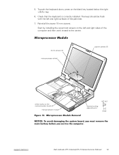
... inward to the center. 3-mm screws (2) microprocessor shield captive screws (3) white marks on the microprocessor board (2) microprocessor module M2.0x3 thermal cooling assembly arm support.dell.com Dell Latitude CPt V-Series/CPx H-Series Service Manual 19
... inward to the center. 3-mm screws (2) microprocessor shield captive screws (3) white marks on the microprocessor board (2) microprocessor module M2.0x3 thermal cooling assembly arm support.dell.com Dell Latitude CPt V-Series/CPx H-Series Service Manual 19

Service Manual
Page 28
... thermal cooling assembly arm and shield to the microprocessor module (see Figure 12). Use a microprocessor extractor tool to secure the microprocessor module and shield. 20 Dell Latitude CPt V-Series/CPx H-Series Service Manual Remove the two 3-mm screws on the front and back edge of the thermal cooling assembly up and away from...
... thermal cooling assembly arm and shield to the microprocessor module (see Figure 12). Use a microprocessor extractor tool to secure the microprocessor module and shield. 20 Dell Latitude CPt V-Series/CPx H-Series Service Manual Remove the two 3-mm screws on the front and back edge of the thermal cooling assembly up and away from...


