Service Manual
Page 7
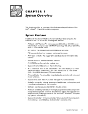
... audio controller with a built-in charge gauge and ExpressCharge technology that charges the battery in about an hour (when the computer is in a Dell portable computer, the Latitude CP and CPi include the following new features: A Mobile Intel® Pentium® II microprocessor 233, 266, or 300 MHz or an Intel Pentium microprocessor with... for a hard-disk drive in the upper PC Card connector. Support for use in the modular bay. Support for up to 128 MB of the Dell® Latitude® CP and CPi portable computers. Support for a zoom video PC Card in the modular bay.
... audio controller with a built-in charge gauge and ExpressCharge technology that charges the battery in about an hour (when the computer is in a Dell portable computer, the Latitude CP and CPi include the following new features: A Mobile Intel® Pentium® II microprocessor 233, 266, or 300 MHz or an Intel Pentium microprocessor with... for a hard-disk drive in the upper PC Card connector. Support for use in the modular bay. Support for up to 128 MB of the Dell® Latitude® CP and CPi portable computers. Support for a zoom video PC Card in the modular bay.
Service Manual
Page 8
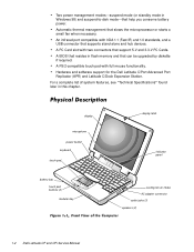
... (2) modular bay display latch indicator panel cooling-fan air intake AC adapter connector audio jacks (3) speakers (2) 1-2 Dell Latitude CP and CPi Service Manual Automatic thermal management that help you conserve battery power. Two power management modessuspend mode (or standby...standards, and a USB connector that can be upgraded by diskette if required. Hardware and software support for the Dell Latitude C/Port Advanced Port Replicator (APR) and Latitude C/Dock Expansion Station. For a complete list of system features, see "Technical Specifications" found later in flash...
... (2) modular bay display latch indicator panel cooling-fan air intake AC adapter connector audio jacks (3) speakers (2) 1-2 Dell Latitude CP and CPi Service Manual Automatic thermal management that help you conserve battery power. Two power management modessuspend mode (or standby...standards, and a USB connector that can be upgraded by diskette if required. Hardware and software support for the Dell Latitude C/Port Advanced Port Replicator (APR) and Latitude C/Dock Expansion Station. For a complete list of system features, see "Technical Specifications" found later in flash...
Service Manual
Page 10
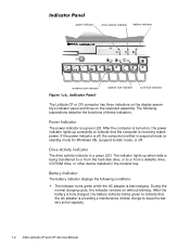
...or other device installed in suspend mode (or standby mode for Windows 98), suspend-to keep the battery at full capacity. 1-4 Dell Latitude CP and CPi Service Manual The battery indicator displays the following subsections describe the functions of these indicators. The following conditions: The indicator turns green... is off . power indicator drive activity indicator battery indicator numbers lock indicator capitals lock indicator scroll lock indicator The Latitude CP or CPi computer has three indicators on the display assembly's indicator panel and three on without blinking.
...or other device installed in suspend mode (or standby mode for Windows 98), suspend-to keep the battery at full capacity. 1-4 Dell Latitude CP and CPi Service Manual The battery indicator displays the following subsections describe the functions of these indicators. The following conditions: The indicator turns green... is off . power indicator drive activity indicator battery indicator numbers lock indicator capitals lock indicator scroll lock indicator The Latitude CP or CPi computer has three indicators on the display assembly's indicator panel and three on without blinking.
Service Manual
Page 11
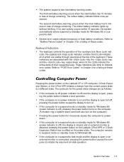
... the display is closed, and no external monitor is in Chapter 3 for Windows 98). If the computer is on (power indicator is on the Latitude CP or CPi computer, C/Dock Expansion Station, or the C/Port APR initiates a change from -disk operation. The computer remains in suspend mode (or standby mode...ring or system alarm event will also turn on the computer.) Pressing the power button for 4 seconds causes the computer to turn on the Latitude C/Port APR or C/Dock Expansion Station has no user activity occurs within 15 seconds, the system automatically enters suspend (or standby mode for ...
... the display is closed, and no external monitor is in Chapter 3 for Windows 98). If the computer is on (power indicator is on the Latitude CP or CPi computer, C/Dock Expansion Station, or the C/Port APR initiates a change from -disk operation. The computer remains in suspend mode (or standby mode...ring or system alarm event will also turn on the computer.) Pressing the power button for 4 seconds causes the computer to turn on the Latitude C/Port APR or C/Dock Expansion Station has no user activity occurs within 15 seconds, the system automatically enters suspend (or standby mode for ...
Service Manual
Page 12
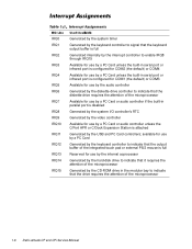
... unless the C/Port APR or C/Dock Expansion Station is attached Generated by the keyboard controller to indicate that the output buffer of the microprocessor 1-6 Dell Latitude CP and CPi Service Manual IRQ0 IRQ1 IRQ2 IRQ3 IRQ4 IRQ5 IRQ6 IRQ7 IRQ8 IRQ9 IRQ10 IRQ11 IRQ12 IRQ13 IRQ14 IRQ15 Generated by the system timer Generated by...
... unless the C/Port APR or C/Dock Expansion Station is attached Generated by the keyboard controller to indicate that the output buffer of the microprocessor 1-6 Dell Latitude CP and CPi Service Manual IRQ0 IRQ1 IRQ2 IRQ3 IRQ4 IRQ5 IRQ6 IRQ7 IRQ8 IRQ9 IRQ10 IRQ11 IRQ12 IRQ13 IRQ14 IRQ15 Generated by the system timer Generated by...
Service Manual
Page 13
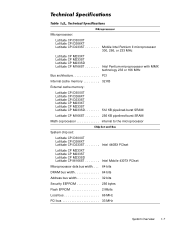
... cache memory 32 KB External cache memory: Latitude CPi D300XT Latitude CPi D266XT Latitude CPi D233ST Latitude CP M233XT Latitude CP M233ST Latitude CP M233SD 512 KB pipelined-burst SRAM Latitude CP M166ST 256 KB pipelined-burst SRAM Math coprocessor internal to the microprocessor System chip set: Latitude CPi D300XT Latitude CPi D266XT Latitude CPi D233ST Intel 440BX PCIset Latitude CP M233XT Latitude CP M233ST Latitude CP M233SD Latitude CP M166ST Intel Mobile 430TX PCIset Microprocessor data bus...
... cache memory 32 KB External cache memory: Latitude CPi D300XT Latitude CPi D266XT Latitude CPi D233ST Latitude CP M233XT Latitude CP M233ST Latitude CP M233SD 512 KB pipelined-burst SRAM Latitude CP M166ST 256 KB pipelined-burst SRAM Math coprocessor internal to the microprocessor System chip set: Latitude CPi D300XT Latitude CPi D266XT Latitude CPi D233ST Intel 440BX PCIset Latitude CP M233XT Latitude CP M233ST Latitude CP M233SD Latitude CP M166ST Intel Mobile 430TX PCIset Microprocessor data bus...
Service Manual
Page 14
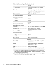
... connector. The Microsoft Windows NT ® 4.0 operating system does not support zoom video. 2 The Latitude CP and CPi do not support memory modules from previous models of Dell portable computers, such as the Latitude XP, XPi, XPi CD, and LM. 1-8 Dell Latitude CP and CPi Service Manual unidirectional, bidirectional, or ECP Video one 15-hole connector PS/2 one 6-hole...
... connector. The Microsoft Windows NT ® 4.0 operating system does not support zoom video. 2 The Latitude CP and CPi do not support memory modules from previous models of Dell portable computers, such as the Latitude XP, XPi, XPi CD, and LM. 1-8 Dell Latitude CP and CPi Service Manual unidirectional, bidirectional, or ECP Video one 15-hole connector PS/2 one 6-hole...
Service Manual
Page 16
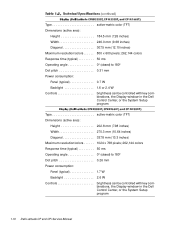
...pitch 0.31 mm Power consumption: Panel (typical 0.7 W Backlight 1.6 or 2.4 W Controls brightness can be controlled with key combinations, the Display window in the Dell Control Center, or the System Setup program Type active-matrix color (TFT) Dimensions (active area): Height 202.8 mm (7.98 inches) Width 270.3 mm (10...Dot pitch 0.26 mm Power consumption: Panel (typical 1.7 W Backlight 2.6 W Controls brightness can be controlled with key combinations, the Display window in the Dell Control Center, or the System Setup program 1-10 Dell Latitude CP and CPi Service Manual
...pitch 0.31 mm Power consumption: Panel (typical 0.7 W Backlight 1.6 or 2.4 W Controls brightness can be controlled with key combinations, the Display window in the Dell Control Center, or the System Setup program Type active-matrix color (TFT) Dimensions (active area): Height 202.8 mm (7.98 inches) Width 270.3 mm (10...Dot pitch 0.26 mm Power consumption: Panel (typical 1.7 W Backlight 2.6 W Controls brightness can be controlled with key combinations, the Display window in the Dell Control Center, or the System Setup program 1-10 Dell Latitude CP and CPi Service Manual
Service Manual
Page 18
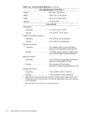
...;F) 3 Battery performance features such as charge time and life span can vary according to the conditions under which the computer and battery are used. 1-12 Dell Latitude CP and CPi Service Manual
...;F) 3 Battery performance features such as charge time and life span can vary according to the conditions under which the computer and battery are used. 1-12 Dell Latitude CP and CPi Service Manual
Service Manual
Page 20
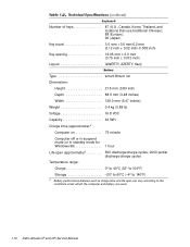
... weigh more or less, depending on its configuration. 7 Measured with a hard-disk drive, a battery in the battery bay, a diskette drive in head-parked position. 1-14 Dell Latitude CP and CPi Service Manual
... weigh more or less, depending on its configuration. 7 Measured with a hard-disk drive, a battery in the battery bay, a diskette drive in head-parked position. 1-14 Dell Latitude CP and CPi Service Manual
Service Manual
Page 21
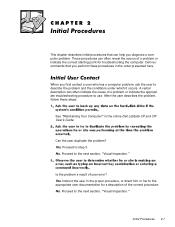
... for troubleshooting the computer. Yes. Initial Procedures 2-1 No. This chapter describes initial procedures that you perform these steps: See "Maintaining Your Computer" in the online Dell Latitude CP and CPi User's Guide. Yes. No. Instruct the user in the order presented here. These procedures can help you first contact a user who has a computer problem...
... for troubleshooting the computer. Yes. Initial Procedures 2-1 No. This chapter describes initial procedures that you perform these steps: See "Maintaining Your Computer" in the online Dell Latitude CP and CPi User's Guide. Yes. No. Instruct the user in the order presented here. These procedures can help you first contact a user who has a computer problem...
Service Manual
Page 22
... pressed or the AC adapter is amber (steadily on state. then replace the battery or connect the computer to AC power to -disk mode. 2-2 Dell Latitude CP and CPi Service Manual Press the power button for that condition: Power indicator is already turned off . The system is off or in the power-on or...
... pressed or the AC adapter is amber (steadily on state. then replace the battery or connect the computer to AC power to -disk mode. 2-2 Dell Latitude CP and CPi Service Manual Press the power button for that condition: Power indicator is already turned off . The system is off or in the power-on or...
Service Manual
Page 24
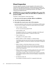
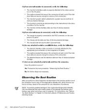
... inspection as described in Chapter 4 of obvious physical damage. The monitor's power cable is attached to a power source and free of the Dell Latitude CP Reference and Troubleshooting Guide. 2-4 Dell Latitude CP and CPi Service Manual The mouse's ball and push buttons operate freely. Proceed to the next procedure, "Observing the Boot Routine." For instructions, see "Before...
... inspection as described in Chapter 4 of obvious physical damage. The monitor's power cable is attached to a power source and free of the Dell Latitude CP Reference and Troubleshooting Guide. 2-4 Dell Latitude CP and CPi Service Manual The mouse's ball and push buttons operate freely. Proceed to the next procedure, "Observing the Boot Routine." For instructions, see "Before...
Service Manual
Page 26
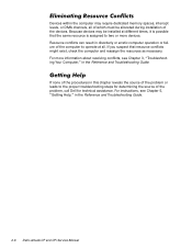
... might exist, check the computer and reassign the resources as necessary. For instructions, see Chapter 3, "Troubleshooting Your Computer," in the Reference and Troubleshooting Guide. 2-6 Dell Latitude CP and CPi Service Manual For more devices. Because devices may require dedicated memory spaces, interrupt levels, or DMA channels, all . Devices within the computer may be installed...
... might exist, check the computer and reassign the resources as necessary. For instructions, see Chapter 3, "Troubleshooting Your Computer," in the Reference and Troubleshooting Guide. 2-6 Dell Latitude CP and CPi Service Manual For more devices. Because devices may require dedicated memory spaces, interrupt levels, or DMA channels, all . Devices within the computer may be installed...
Service Manual
Page 28
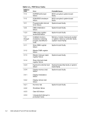
... board faulty Display initialization failure Display retrace test failure No timer tick System board faulty Shutdown failure Gate A20 failure Unexpected interrupt in protected mode 3-2 Dell Latitude CP and CPi Service Manual
... board faulty Display initialization failure Display retrace test failure No timer tick System board faulty Shutdown failure Gate A20 failure Unexpected interrupt in protected mode 3-2 Dell Latitude CP and CPi Service Manual
Service Manual
Page 30
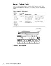
Indicator flashes alternately green and amber. abnormal charge; abnormal charge current Fatal Cell imbalance; abnormal discharge; Replace the battery. Temporary Over temperature; In the event of a battery failure, the battery indicator displays indicator codes that identify the severity of the problem. critical discharge Turn off the computer and let the battery and computer cool to room temperature. Indicator flashes amber four times per second. The following table lists these failure codes. battery indicator 3-4 Dell Latitude CP and CPi Service Manual
Indicator flashes alternately green and amber. abnormal charge; abnormal charge current Fatal Cell imbalance; abnormal discharge; Replace the battery. Temporary Over temperature; In the event of a battery failure, the battery indicator displays indicator codes that identify the severity of the problem. critical discharge Turn off the computer and let the battery and computer cool to room temperature. Indicator flashes amber four times per second. The following table lists these failure codes. battery indicator 3-4 Dell Latitude CP and CPi Service Manual

Service Manual
Page 32
... respond to commands from computer. System board faulty. Computer needs rebooting. Computer cannot identify PC Card. Defective or unformatted diskette. Hard-disk drive faulty. 3-6 Dell Latitude CP and CPi Service Manual operation cannot be missing from the computer. The diskette may be completed. Operating system unable to commands from computer. Diskette writeprotected Drive not...
... respond to commands from computer. System board faulty. Computer needs rebooting. Computer cannot identify PC Card. Defective or unformatted diskette. Hard-disk drive faulty. 3-6 Dell Latitude CP and CPi Service Manual operation cannot be missing from the computer. The diskette may be completed. Operating system unable to commands from computer. Diskette writeprotected Drive not...

Service Manual
Page 34
... or hard-disk drive from harddisk drive or diskette drive. Optional ROM in external device failed. No boot sector on diskette or hard-disk drive. 3-8 Dell Latitude CP and CPi Service Manual
... or hard-disk drive from harddisk drive or diskette drive. Optional ROM in external device failed. No boot sector on diskette or hard-disk drive. 3-8 Dell Latitude CP and CPi Service Manual
Service Manual
Page 75
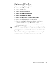
NOTES: The replacement display-assembly top cover assembly includes two badges, one for Dell Latitude CP and one for the Dell Latitude CPi. Removing and Replacing Parts 4-39 When reinstalling the display assembly, install the four screws securing the hinges at the old cover to determine which badge is appropriate, and then attach the appropriate badge to the display-assembly top cover. Look at the locations marked by arrows on the face of each hinge. To remove a brace, remove the 3-mm screw securing the brace to the new cover.
NOTES: The replacement display-assembly top cover assembly includes two badges, one for Dell Latitude CP and one for the Dell Latitude CPi. Removing and Replacing Parts 4-39 When reinstalling the display assembly, install the four screws securing the hinges at the old cover to determine which badge is appropriate, and then attach the appropriate badge to the display-assembly top cover. Look at the locations marked by arrows on the face of each hinge. To remove a brace, remove the 3-mm screw securing the brace to the new cover.
Replacement Instructions
Page 42
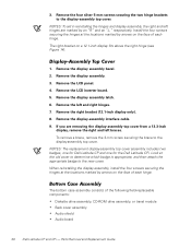
... Remove the display-assembly interface cable. 9. NOTES: The replacement display-assembly top cover assembly includes two badges, one for Dell Latitude CP and one for the Dell Latitude CPi. When reinstalling the display assembly, install the four screws securing the hinges at the locations marked by arrows on a 12...components: Diskette drive assembly, CD-ROM drive assembly, or travel module Back cover assembly Audio shield Audio board 36 Dell Latitude CP and CPi - Parts Removal and Replacement Guide Remove the four silver 5-mm screws securing the two hinge brackets to the display-assembly ...
... Remove the display-assembly interface cable. 9. NOTES: The replacement display-assembly top cover assembly includes two badges, one for Dell Latitude CP and one for the Dell Latitude CPi. When reinstalling the display assembly, install the four screws securing the hinges at the locations marked by arrows on a 12...components: Diskette drive assembly, CD-ROM drive assembly, or travel module Back cover assembly Audio shield Audio board 36 Dell Latitude CP and CPi - Parts Removal and Replacement Guide Remove the four silver 5-mm screws securing the two hinge brackets to the display-assembly ...


