
User Guide
Page 3
... PowerConnect 3424 21 PowerConnect 3424P 21 PowerConnect 3448 22 PowerConnect 3448P 22 Stacking Overview 22 Understanding the Stack Topology 23 Stacking Failover Topology 23 Stacking Members and Unit ID 23 Removing and Replacing Stacking Members 24 Exchanging Stacking Members 25 Switching from the Stack Master to the Backup Stack Master. . . . . . 27 Features Overview 28 Power over Ethernet...
... PowerConnect 3424 21 PowerConnect 3424P 21 PowerConnect 3448 22 PowerConnect 3448P 22 Stacking Overview 22 Understanding the Stack Topology 23 Stacking Failover Topology 23 Stacking Members and Unit ID 23 Removing and Replacing Stacking Members 24 Exchanging Stacking Members 25 Switching from the Stack Master to the Backup Stack Master. . . . . . 27 Features Overview 28 Power over Ethernet...

User Guide
Page 8
...Configuring GARP 270 Defining GARP Timers 270 Configuring the Spanning Tree Protocol 273 Defining STP Global Settings 274 Defining STP Port Settings 280 Defining STP LAG Settings 284 Defining Rapid Spanning Tree 288 Configuring Multiple Spanning Tree 291 Defining MSTP Interface... to VLANs 310 Configuring GVRP Parameters 312 Configuring Private VLANs 315 Aggregating Ports 319 Defining LACP Parameters 319 Defining LACP Parameters 320 Defining LAG Membership 322 Multicast Forwarding Support 324 Defining Multicast Global Parameters 324 Adding Bridge Multicast Address Members 326 ...
...Configuring GARP 270 Defining GARP Timers 270 Configuring the Spanning Tree Protocol 273 Defining STP Global Settings 274 Defining STP Port Settings 280 Defining STP LAG Settings 284 Defining Rapid Spanning Tree 288 Configuring Multiple Spanning Tree 291 Defining MSTP Interface... to VLANs 310 Configuring GVRP Parameters 312 Configuring Private VLANs 315 Aggregating Ports 319 Defining LACP Parameters 319 Defining LACP Parameters 320 Defining LAG Membership 322 Multicast Forwarding Support 324 Defining Multicast Global Parameters 324 Adding Bridge Multicast Address Members 326 ...

User Guide
Page 22
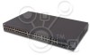
... the device is managed. PowerConnect 3448 and PowerConnect 3448P Stacking Overview PowerConnect 3424/P and PowerConnect 3448/P stacking provides multiple switch management through which can operate as stacking ports when the device is in stand-alone mode, or as stand-alone units. www.dell.com | support.dell.com PowerConnect 3448 The PowerConnect 3448 provides 48 10/100Mbps ports plus two SFP ports, and two Copper ports which the stack is...
... the device is managed. PowerConnect 3448 and PowerConnect 3448P Stacking Overview PowerConnect 3424/P and PowerConnect 3448/P stacking provides multiple switch management through which can operate as stacking ports when the device is in stand-alone mode, or as stand-alone units. www.dell.com | support.dell.com PowerConnect 3448 The PowerConnect 3448 provides 48 10/100Mbps ports plus two SFP ports, and two Copper ports which the stack is...

User Guide
Page 24
...the stack. During the Warm Standby, the Master and the Backup Master are either designated as Master Unit or Backup Master Unit. www.dell.com | support.dell.com Once the user selects a different Unit ID, it is elected as the Master. • If two Master enabled stacking members are...The Stack Master and the Backup Master maintain a Warm Standby. The Dynamic configuration is inserted in the stack has a specific Unit ID, port type, and port number, which are reserved for the Stack Master if a failover occurs. Configuration files are considered the same age if they were inserted within...
...the stack. During the Warm Standby, the Master and the Backup Master are either designated as Master Unit or Backup Master Unit. www.dell.com | support.dell.com Once the user selects a different Unit ID, it is elected as the Master. • If two Master enabled stacking members are...The Stack Master and the Backup Master maintain a Warm Standby. The Dynamic configuration is inserted in the stack has a specific Unit ID, port type, and port number, which are reserved for the Stack Master if a failover occurs. Configuration files are considered the same age if they were inserted within...

User Guide
Page 28
...and the packets at the head of the queue are temporarily halted to power sources. Flow Control Support (IEEE 802.3X) Flow control enables lower speed devices to devices over Ethernet". Transmissions are forwarded before packets at the end of Line (HOL) blocking results in the ... over Ethernet, see the latest software version Release Notes. Head of Line Blocking Head of the queue. Back Pressure Support On half-duplex links, the receiving port prevents buffer overflows by traffic competing for placing network devices next to prevent buffer overflows. www.dell.com | support.dell.com...
...and the packets at the head of the queue are temporarily halted to power sources. Flow Control Support (IEEE 802.3X) Flow control enables lower speed devices to devices over Ethernet". Transmissions are forwarded before packets at the end of Line (HOL) blocking results in the ... over Ethernet, see the latest software version Release Notes. Head of Line Blocking Head of the queue. Back Pressure Support On half-duplex links, the receiving port prevents buffer overflows by traffic competing for placing network devices next to prevent buffer overflows. www.dell.com | support.dell.com...

User Guide
Page 29
...PowerConnect 3400 series enhances auto negotiation by providing port advertisement. Port advertisement allows the system administrator to advertise modes of their transmission capabilities. Automatic Aging for MAC Addresses MAC addresses, from incoming frames. This prevents the Bridging Table from incoming packets. For more information, see "Defining Port...." The device reserves specific MAC addresses for hubs and switches is received for ports or LAGs, see "Viewing Dynamic Addresses." MDI/MDIX Support The device automatically detects whether the cable connected to 8K...
...PowerConnect 3400 series enhances auto negotiation by providing port advertisement. Port advertisement allows the system administrator to advertise modes of their transmission capabilities. Automatic Aging for MAC Addresses MAC addresses, from incoming frames. This prevents the Bridging Table from incoming packets. For more information, see "Defining Port...." The device reserves specific MAC addresses for hubs and switches is received for ports or LAGs, see "Viewing Dynamic Addresses." MDI/MDIX Support The device automatically detects whether the cable connected to 8K...

User Guide
Page 30
... "IGMP Snooping." For more information, see "Enabling Storm Control." 30 Introduction www.dell.com | support.dell.com VLAN-aware MAC-based Switching The device always performs VLAN-aware bridging. Layer 2 Multicast service is where a single frame is not associated with any port are sending Multicast frames. For more information, see "Assigning Multicast Forward All Parameters...
... "IGMP Snooping." For more information, see "Enabling Storm Control." 30 Introduction www.dell.com | support.dell.com VLAN-aware MAC-based Switching The device always performs VLAN-aware bridging. Layer 2 Multicast service is where a single frame is not associated with any port are sending Multicast frames. For more information, see "Assigning Multicast Forward All Parameters...

User Guide
Page 31
... as belonging to a VLAN based on either the VLAN tag or based on a combination of the ingress port and packet contents. When GVRP is a standard Layer 2 switch requirement that comprise a single broadcast domain. GVRP Support GARP VLAN Registration Protocol (GVRP) provides IEEE 802.1Q-compliant VLAN pruning and dynamic VLAN creation on their...
... as belonging to a VLAN based on either the VLAN tag or based on a combination of the ingress port and packet contents. When GVRP is a standard Layer 2 switch requirement that comprise a single broadcast domain. GVRP Support GARP VLAN Registration Protocol (GVRP) provides IEEE 802.1Q-compliant VLAN pruning and dynamic VLAN creation on their...

User Guide
Page 32
.... Link Aggregation Link Aggregation Up to eight Aggregated Links may be transmitted. LACP automatically determines, configures, binds, and monitors the port binding within MSTP Regions (MST Regions). Rapid Spanning Tree (RSTP) detects uses of devices. For more information, see "Defining Rapid... balancing scenario. For more information enabling Fast Link for ports and LAGs, see "Configuring the Spanning Tree Protocol". For more information, see "Defining STP Port Settings" or "Defining Static Addresses." www.dell.com | support.dell.com Fast Link STP can take 30-60 seconds for...
.... Link Aggregation Link Aggregation Up to eight Aggregated Links may be transmitted. LACP automatically determines, configures, binds, and monitors the port binding within MSTP Regions (MST Regions). Rapid Spanning Tree (RSTP) detects uses of devices. For more information, see "Defining Rapid... balancing scenario. For more information enabling Fast Link for ports and LAGs, see "Configuring the Spanning Tree Protocol". For more information, see "Defining STP Port Settings" or "Defining Static Addresses." www.dell.com | support.dell.com Fast Link STP can take 30-60 seconds for...

User Guide
Page 33
...configuration is a spin-off of the 802.1Q (VLANs) standard. 802.1p establishes eight levels of Service Features Class Of Service 802.1p Support The IEEE 802.1p signaling technique is an OSI Layer 2 standard for marking and prioritizing network traffic at the data link/MAC sub-layer...1p is stored in the form of a collection of a community string and its access privileges. The Configuration file includes both system wide and port specific device configuration. Events are stored and manipulated as SNMP traps to a Trap Recipient List. Web Based Management With the web based management, ...
...configuration is a spin-off of the 802.1Q (VLANs) standard. 802.1p establishes eight levels of Service Features Class Of Service 802.1p Support The IEEE 802.1p signaling technique is an OSI Layer 2 standard for marking and prioritizing network traffic at the data link/MAC sub-layer...1p is stored in the form of a collection of a community string and its access privileges. The Configuration file includes both system wide and port specific device configuration. Events are stored and manipulated as SNMP traps to a Trap Recipient List. Web Based Management With the web based management, ...

User Guide
Page 34
... Domain Name System (DNS) converts user-defined domain names into a numeric IP address. www.dell.com | support.dell.com TFTP Trivial File Transfer Protocol The device supports boot image, software, and configuration upload/download via TFTP. For more information, see "Configuring ...to SNMP, which allows network device management and monitoring). SNTP The Simple Network Time Protocol (SNTP) assures accurate network Ethernet Switch clock time synchronization up to SNMP which provides comprehensive network traffic monitoring capabilities (as possible to be stored, examined and...
... Domain Name System (DNS) converts user-defined domain names into a numeric IP address. www.dell.com | support.dell.com TFTP Trivial File Transfer Protocol The device supports boot image, software, and configuration upload/download via TFTP. For more information, see "Configuring ...to SNMP, which allows network device management and monitoring). SNTP The Simple Network Time Protocol (SNTP) assures accurate network Ethernet Switch clock time synchronization up to SNMP which provides comprehensive network traffic monitoring capabilities (as possible to be stored, examined and...

User Guide
Page 35
... enables an SSH client to users with specific MAC addresses. This connection provides functionality that provides a secure, remote connection to an inbound telnet connection. Locked Port Support Locked Port increases network security by limiting access on a per -user authentication information, such as user name, password and accounting information. For more information, see "Configuring...
... enables an SSH client to users with specific MAC addresses. This connection provides functionality that provides a secure, remote connection to an inbound telnet connection. Locked Port Support Locked Port increases network security by limiting access on a per -user authentication information, such as user name, password and accounting information. For more information, see "Configuring...

User Guide
Page 36
The document provides information about the CLI commands used to configure the device. www.dell.com | support.dell.com Password Management Password management provides increased network security and improved password control. Additional CLI Documentation The CLI Reference Guide, which is available on Password ...
The document provides information about the CLI commands used to configure the device. www.dell.com | support.dell.com Password Management Password management provides increased network security and improved password control. Additional CLI Documentation The CLI Reference Guide, which is available on Password ...

User Guide
Page 38
... is marked with the following ports: • 48 FE ports - Designated as stacking ports, or used to select the unit number. The upper row of ports is prevented. G2 which are fiber ports and ports G3- Console Port RPS Connector Power Connector PowerConnect 3448 Port Description The PowerConnect 3448 device is configured with even numbers 2-48. Figure 2-3. www.dell.com | support.dell.com There are all the...
... is marked with the following ports: • 48 FE ports - Designated as stacking ports, or used to select the unit number. The upper row of ports is prevented. G2 which are fiber ports and ports G3- Console Port RPS Connector Power Connector PowerConnect 3448 Port Description The PowerConnect 3448 device is configured with even numbers 2-48. Figure 2-3. www.dell.com | support.dell.com There are all the...

User Guide
Page 40
...left side of links, power supplies, fans, and system diagnostics. Port LEDs Each 10/100/1000 Base-T port and 10/100 Base-T port has two LEDs. The following physical dimensions: PoE Model: &#...port, while the link/duplex/activity LED is located on the PowerConnect 3424 /P and PowerConnect 3448/P has two LEDs marked as LNK/ACT. 40 Hardware Description www.dell.com | support.dell.com Physical Dimensions The PowerConnect 3424/P and PowerConnect 3448/P devices have the following figure illustrates the 10/100 Base-T port LEDs on The PowerConnect 3424 /P and PowerConnect 3448/P switches...
...left side of links, power supplies, fans, and system diagnostics. Port LEDs Each 10/100/1000 Base-T port and 10/100 Base-T port has two LEDs. The following physical dimensions: PoE Model: &#...port, while the link/duplex/activity LED is located on the PowerConnect 3424 /P and PowerConnect 3448/P has two LEDs marked as LNK/ACT. 40 Hardware Description www.dell.com | support.dell.com Physical Dimensions The PowerConnect 3424/P and PowerConnect 3448/P devices have the following figure illustrates the 10/100 Base-T port LEDs on The PowerConnect 3424 /P and PowerConnect 3448/P switches...

User Guide
Page 42
.... The port is operating at 100 Mbps. For more information about Power over Ethernet power allotments, see "Managing Power over Ethernet". An overload or short has occurred on the Powered Device. For more information about Powered Devices, see "Managing Power over Ethernet". www.dell.com | support.dell.com The RJ-45 LED indications for PowerConnect 3424P and PowerConnect 3448P...
.... The port is operating at 100 Mbps. For more information about Power over Ethernet power allotments, see "Managing Power over Ethernet". An overload or short has occurred on the Powered Device. For more information about Powered Devices, see "Managing Power over Ethernet". www.dell.com | support.dell.com The RJ-45 LED indications for PowerConnect 3424P and PowerConnect 3448P...

User Guide
Page 44
... Green Static All device fans are operating normally. Red Static One or more of The PowerConnect 3424 /P and PowerConnect 3448/P devices provide information about the power supplies, fans, thermal conditions, and diagnostics. The ...dell.com | support.dell.com System LEDs The system LEDs of the device fans is currently operating. System LED Indicators LED Power Supply (PWR) Redundant Power Supply (RPS) (models: 3424 and 3448 ) Redundant Power Supply (RPS) (models: 3424P and 3448P ) Diagnostics (DIAG) Temperature (TEMP) Fan (FAN) Color Green Static OFF Green Static Description The switch...
... Green Static All device fans are operating normally. Red Static One or more of The PowerConnect 3424 /P and PowerConnect 3448/P devices provide information about the power supplies, fans, thermal conditions, and diagnostics. The ...dell.com | support.dell.com System LEDs The system LEDs of the device fans is currently operating. System LED Indicators LED Power Supply (PWR) Redundant Power Supply (RPS) (models: 3424 and 3448 ) Redundant Power Supply (RPS) (models: 3424P and 3448P ) Diagnostics (DIAG) Temperature (TEMP) Fan (FAN) Color Green Static OFF Green Static Description The switch...
User Guide
Page 46
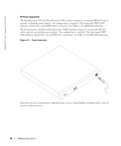
... provide a redundant power option. Figure 2-11. See Table 2-5 for RPS LED definition. Power Connection When the device is connected. www.dell.com | support.dell.com DC Power Supply Unit The PowerConnect 3424 and PowerConnect 3448 switches connect to an external RPS-600 unit to provide a redundant power option. No configuration is required. No configuration is required. See...
... provide a redundant power option. Figure 2-11. See Table 2-5 for RPS LED definition. Power Connection When the device is connected. www.dell.com | support.dell.com DC Power Supply Unit The PowerConnect 3424 and PowerConnect 3448 switches connect to an external RPS-600 unit to provide a redundant power option. No configuration is required. No configuration is required. See...

User Guide
Page 50
...When mounting multiple devices into a rack, mount the devices from the box and place it on devices connected to The PowerConnect 3424/P and PowerConnect 3448/P devices. Installing in a Rack CAUTION: Read the Safety Information included in a rack or cabinet. Connecting a Redundant ...device from the bottom up. 50 Installing the PowerConnect 3424/P and PowerConnect 3448/P www.dell.com | support.dell.com Unpacking the Device NOTE: Before unpacking the device, inspect the package and immediately report any damage immediately. The Console port is recommended. The RPS connector is on ...
...When mounting multiple devices into a rack, mount the devices from the box and place it on devices connected to The PowerConnect 3424/P and PowerConnect 3448/P devices. Installing in a Rack CAUTION: Read the Safety Information included in a rack or cabinet. Connecting a Redundant ...device from the bottom up. 50 Installing the PowerConnect 3424/P and PowerConnect 3448/P www.dell.com | support.dell.com Unpacking the Device NOTE: Before unpacking the device, inspect the package and immediately report any damage immediately. The Console port is recommended. The RPS connector is on ...

User Guide
Page 51
... the device. 4 Insert the unit into the 48.26 cm (19 inch) rack, ensuring that the rack-mounting holes on the device line up to mount the brackets. Fasten the lower pair of screws before the upper pair of screws. Installing the PowerConnect 3424/P and PowerConnect 3448/P 51 Figure 3-1. The surface must be able... side of the device, ensuring that the mounting holes on the device line up to the mounting holes on the rack. 5 Secure the unit to support the weight of the device and the device cables. 1 Attach the self-adhesive rubber pads on each marked location on the bottom of the chassis...
... the device. 4 Insert the unit into the 48.26 cm (19 inch) rack, ensuring that the rack-mounting holes on the device line up to mount the brackets. Fasten the lower pair of screws before the upper pair of screws. Installing the PowerConnect 3424/P and PowerConnect 3448/P 51 Figure 3-1. The surface must be able... side of the device, ensuring that the mounting holes on the device line up to the mounting holes on the rack. 5 Secure the unit to support the weight of the device and the device cables. 1 Attach the self-adhesive rubber pads on each marked location on the bottom of the chassis...


