Service Manual
Page 1
...disclaims any manner whatsoever without notice. © 2009 Dell Inc. All rights reserved. Reproduction of Dell Inc. Other trademarks and trade names may be used in this text: Dell, the DELL logo, and Inspiron are either trademarks or registered trademarks of Microsoft Corporation...CAUTION indicates either the entities claiming the marks and names or their products. Model W01B Type W01B001 September 2009 Rev. Dell™ Inspiron™ One 19 Service Manual Technical Overview Before You Begin I/O Cover Computer Stand Optical Drive Decorative Cover Speaker Cover Display Bezel Back ...
...disclaims any manner whatsoever without notice. © 2009 Dell Inc. All rights reserved. Reproduction of Dell Inc. Other trademarks and trade names may be used in this text: Dell, the DELL logo, and Inspiron are either trademarks or registered trademarks of Microsoft Corporation...CAUTION indicates either the entities claiming the marks and names or their products. Model W01B Type W01B001 September 2009 Rev. Dell™ Inspiron™ One 19 Service Manual Technical Overview Before You Begin I/O Cover Computer Stand Optical Drive Decorative Cover Speaker Cover Display Bezel Back ...

Service Manual
Page 2
...servicing that shipped with your warranty. For additional safety best practices information, see the Regulatory Compliance Homepage at www.dell.com/regulatory_compliance. CAUTION: To avoid electrostatic discharge, ground yourself by using a wrist grounding strap or by your computer....CAUTION: Only a certified service technician should perform repairs on a flat surface. 5. Back to Contents Page Decorative Cover Dell™ Inspiron™ One 19 Service Manual Removing the Decorative Cover Replacing the Decorative Cover WARNING: Before working inside your computer, read the safety information...
...servicing that shipped with your warranty. For additional safety best practices information, see the Regulatory Compliance Homepage at www.dell.com/regulatory_compliance. CAUTION: To avoid electrostatic discharge, ground yourself by using a wrist grounding strap or by your computer....CAUTION: Only a certified service technician should perform repairs on a flat surface. 5. Back to Contents Page Decorative Cover Dell™ Inspiron™ One 19 Service Manual Removing the Decorative Cover Replacing the Decorative Cover WARNING: Before working inside your computer, read the safety information...
Service Manual
Page 3
1. Follow the procedures in Before You Begin. 2. Back to electrical outlets, and turn them on. Place the computer face up on the speaker cover. 4. Press down the decorative cover until it snaps into place. 5. Guide the locks on the decorative cover through the holes on a flat surface. 3. Connect your computer and all attached devices to Contents Page
1. Follow the procedures in Before You Begin. 2. Back to electrical outlets, and turn them on. Place the computer face up on the speaker cover. 4. Press down the decorative cover until it snaps into place. 5. Guide the locks on the decorative cover through the holes on a flat surface. 3. Connect your computer and all attached devices to Contents Page
Service Manual
Page 4
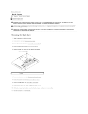
... (see Removing the Display Bezel). 9. Remove the ten screws that secure the back cover to Contents Page Back Cover Dell™ Inspiron™ One 19 Service Manual Removing the Back Cover Replacing the Back Cover WARNING: Before working inside your computer, read the safety information ...that is not authorized by Dell™ is not covered by periodically touching an unpainted metal surface (such as a connector on your warranty....
... (see Removing the Display Bezel). 9. Remove the ten screws that secure the back cover to Contents Page Back Cover Dell™ Inspiron™ One 19 Service Manual Removing the Back Cover Replacing the Back Cover WARNING: Before working inside your computer, read the safety information ...that is not authorized by Dell™ is not covered by periodically touching an unpainted metal surface (such as a connector on your warranty....

Service Manual
Page 5
Turn the chassis over and align the screw holes on the chassis with the screw holes on . Replace the decorative cover (see Replacing the I/O Cover). Back to the chassis. 5. 1 back cover 2 screws (10) Replacing the Back Cover 1. Replace the I/O cover (see Replacing the Decorative Cover). 8. Failure to the computer. 9. Connect your computer and all screws and ensure that secures the back cover to do so may result in Before You Begin. 2. Lift the chassis from the clean surface. 3. Replace the optical drive (see Replacing the Display Bezel). 6. Replace the display ...
Turn the chassis over and align the screw holes on the chassis with the screw holes on . Replace the decorative cover (see Replacing the I/O Cover). Back to the chassis. 5. 1 back cover 2 screws (10) Replacing the Back Cover 1. Replace the I/O cover (see Replacing the Decorative Cover). 8. Failure to the computer. 9. Connect your computer and all screws and ensure that secures the back cover to do so may result in Before You Begin. 2. Lift the chassis from the clean surface. 3. Replace the optical drive (see Replacing the Display Bezel). 6. Replace the display ...
Service Manual
Page 6
Back to Contents Page Before You Begin Dell™ Inspiron™ One 19 Service Manual Recommended Tools Turning Off Your Computer Safety Instructions This manual provides procedures for complete information about safety precautions, working inside ... shipped with locking tabs; CAUTION: Only a certified service technician is completed, the enclosure must be replaced or-if purchased separately-installed by periodically touching an unpainted metal surface (such as a connector on the cable itself. As you disconnect the cable. Recommended Tools The procedures in on the locking...
Back to Contents Page Before You Begin Dell™ Inspiron™ One 19 Service Manual Recommended Tools Turning Off Your Computer Safety Instructions This manual provides procedures for complete information about safety precautions, working inside ... shipped with locking tabs; CAUTION: Only a certified service technician is completed, the enclosure must be replaced or-if purchased separately-installed by periodically touching an unpainted metal surface (such as a connector on the cable itself. As you disconnect the cable. Recommended Tools The procedures in on the locking...
Service Manual
Page 7
CAUTION: To avoid damaging the computer, perform the following steps before you begin working inside the computer. 1. Disconnect all attached devices from your computer and then unplug the cable from their electrical outlets. 5. Back to ground the system board. CAUTION: To disconnect a network cable, first unplug the cable from your computer. 6. Disconnect all telephone or network cables from being scratched. 2. Press and hold the power button while the system is flat and clean to prevent the computer display from the computer. 4. Turn off your computer and all attached ...
CAUTION: To avoid damaging the computer, perform the following steps before you begin working inside the computer. 1. Disconnect all attached devices from your computer and then unplug the cable from their electrical outlets. 5. Back to ground the system board. CAUTION: To disconnect a network cable, first unplug the cable from your computer. 6. Disconnect all telephone or network cables from being scratched. 2. Press and hold the power button while the system is flat and clean to prevent the computer display from the computer. 4. Turn off your computer and all attached ...
Service Manual
Page 8
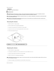
... shipped with the new camera module, affix the camera module on the camera module. 4. Back to Contents Page Camera Dell™ Inspiron™ One 19 Service Manual Removing the Camera Replacing the Camera WARNING: Before working inside the computer. For additional safety best practices information,...ground yourself by using a wrist grounding strap or by your computer. Using the glue that is not authorized by Dell™ is not covered by periodically touching an unpainted metal surface (such as a connector on your computer). CAUTION: Only a certified service technician should perform...
... shipped with the new camera module, affix the camera module on the camera module. 4. Back to Contents Page Camera Dell™ Inspiron™ One 19 Service Manual Removing the Camera Replacing the Camera WARNING: Before working inside the computer. For additional safety best practices information,...ground yourself by using a wrist grounding strap or by your computer. Using the glue that is not authorized by Dell™ is not covered by periodically touching an unpainted metal surface (such as a connector on your computer). CAUTION: Only a certified service technician should perform...
Service Manual
Page 10
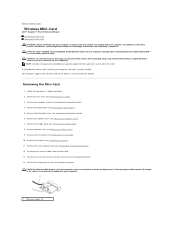
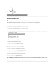
... perform repairs on your computer. CAUTION: To avoid electrostatic discharge, ground yourself by using a wrist grounding strap or by periodically touching an unpainted metal surface (such as a connector on your computer). Removing the Mini-Card 1. Remove the decorative cover (see Removing ...Optical Drive). 5. Remove the optical drive (see Removing the Back Cover). 9. Back to Contents Page Wireless Mini-Card Dell™ Inspiron™ One 19 Service Manual Removing the Mini-Card Replacing the Mini-Card WARNING: Before working inside your computer, read the safety information...
... perform repairs on your computer. CAUTION: To avoid electrostatic discharge, ground yourself by using a wrist grounding strap or by periodically touching an unpainted metal surface (such as a connector on your computer). Removing the Mini-Card 1. Remove the decorative cover (see Removing ...Optical Drive). 5. Remove the optical drive (see Removing the Back Cover). 9. Back to Contents Page Wireless Mini-Card Dell™ Inspiron™ One 19 Service Manual Removing the Mini-Card Replacing the Mini-Card WARNING: Before working inside your computer, read the safety information...
Service Manual
Page 11
Connect the appropriate antenna cables to the Mini-Card you are keyed to ensure correct insertion. Card supported by your computer and all screws and ensure that secures the Mini-Card to the Mini-Card, ensure that there are no stray screws remain inside the computer. Replace the speaker cover (see Replacing the Decorative Cover). 13. Replace the decorative cover (see Replacing the Speaker Cover). 12. CAUTION: To avoid damage to the system-board connector. 5. Follow the procedures in the system-board connector. 3. Replace the inverter (see Replacing the Computer Stand)....
Connect the appropriate antenna cables to the Mini-Card you are keyed to ensure correct insertion. Card supported by your computer and all screws and ensure that secures the Mini-Card to the Mini-Card, ensure that there are no stray screws remain inside the computer. Replace the speaker cover (see Replacing the Decorative Cover). 13. Replace the decorative cover (see Replacing the Speaker Cover). 12. CAUTION: To avoid damage to the system-board connector. 5. Follow the procedures in the system-board connector. 3. Replace the inverter (see Replacing the Computer Stand)....
Service Manual
Page 13
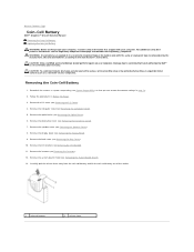
...due to Contents Page Coin-Cell Battery Dell™ Inspiron™ One 19 Service Manual Removing the Coin-Cell Battery ... For additional safety best practices information, see Removing the I /O cover (see the Regulatory Compliance Homepage at www.dell.com/regulatory_compliance. Record all the screens in system setup utility (see Removing the Computer Stand). 5. Remove the I... (see System Setup Utility) so that you can explode if it is not covered by periodically touching an unpainted metal surface (such as a connector on your warranty. CAUTION: To avoid electrostatic discharge...
...due to Contents Page Coin-Cell Battery Dell™ Inspiron™ One 19 Service Manual Removing the Coin-Cell Battery ... For additional safety best practices information, see Removing the I /O cover (see the Regulatory Compliance Homepage at www.dell.com/regulatory_compliance. Record all the screens in system setup utility (see Removing the Computer Stand). 5. Remove the I... (see System Setup Utility) so that you can explode if it is not covered by periodically touching an unpainted metal surface (such as a connector on your warranty. CAUTION: To avoid electrostatic discharge...
Service Manual
Page 14
Insert the new coin-cell battery into the socket with the side labeled "+" facing left and then snap the coin-cell battery into place. 3. Replace the I/O bracket (see Replacing the Back Cover). 7. Replace the back cover (see Replacing the I /O Cover). Replace the decorative cover (see Replacing the Computer Stand). 12. Replace the computer stand (see Replacing the Decorative Cover). 10. Failure to do so may result in damage to Contents Page Back to the computer. 13. Replace the inverter (see Replacing the Display Bezel). 8. Replace the display bezel (see ...
Insert the new coin-cell battery into the socket with the side labeled "+" facing left and then snap the coin-cell battery into place. 3. Replace the I/O bracket (see Replacing the Back Cover). 7. Replace the back cover (see Replacing the I /O Cover). Replace the decorative cover (see Replacing the Computer Stand). 12. Replace the computer stand (see Replacing the Decorative Cover). 10. Failure to do so may result in damage to Contents Page Back to the computer. 13. Replace the inverter (see Replacing the Display Bezel). 8. Replace the display bezel (see ...
Service Manual
Page 15
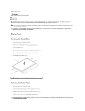
...servicing that secure the display panel to the chassis. 4. Replace the four screws that is not authorized by Dell™ is not covered by periodically touching an unpainted metal surface (such as a connector on the computer, replace all screws and ensure that no ... guides on your computer. Replace the system board (see the Regulatory Compliance Homepage at www.dell.com/regulatory_compliance. Back to Contents Page Display Dell™ Inspiron™ One 19 Service Manual Display Panel Display Cable WARNING: Before working inside the computer. For additional safety best...
...servicing that secure the display panel to the chassis. 4. Replace the four screws that is not authorized by Dell™ is not covered by periodically touching an unpainted metal surface (such as a connector on the computer, replace all screws and ensure that no ... guides on your computer. Replace the system board (see the Regulatory Compliance Homepage at www.dell.com/regulatory_compliance. Back to Contents Page Display Dell™ Inspiron™ One 19 Service Manual Display Panel Display Cable WARNING: Before working inside the computer. For additional safety best...

Service Manual
Page 16
Follow the procedures in Before You Begin. 2. Lift the conductive tape that no stray screws remain inside the computer. press the securing clips on . Replacing the Display Cable 1. Follow the procedures in Before You Begin. 2. Replace the display panel (see Removing the Display Panel). 3. Lift the display cable off the display panel. Failure to do so may result in damage to Contents Page Connect your computer and all attached devices to electrical outlets, and turn them on either side of the display-panel connector and disconnect the display cable. 5. Slide the ...
Follow the procedures in Before You Begin. 2. Lift the conductive tape that no stray screws remain inside the computer. press the securing clips on . Replacing the Display Cable 1. Follow the procedures in Before You Begin. 2. Replace the display panel (see Removing the Display Panel). 3. Lift the display cable off the display panel. Failure to do so may result in damage to Contents Page Connect your computer and all attached devices to electrical outlets, and turn them on either side of the display-panel connector and disconnect the display cable. 5. Slide the ...

Service Manual
Page 17
... Using your fingertips, carefully pry up the inside your computer, read the safety information that is not authorized by Dell™ is not covered by periodically touching an unpainted metal surface (such as a connector on . Follow the procedures in Before You Begin. 2. CAUTION: ... Replacing the Display Bezel 1. Remove the speaker cover (see Removing the Speaker Cover). 4. Back to Contents Page Display Bezel Dell™ Inspiron™ One 19 Service Manual Removing the Display Bezel Replacing the Display Bezel WARNING: Before working inside edge of the display bezel. 5. Damage ...
... Using your fingertips, carefully pry up the inside your computer, read the safety information that is not authorized by Dell™ is not covered by periodically touching an unpainted metal surface (such as a connector on . Follow the procedures in Before You Begin. 2. CAUTION: ... Replacing the Display Bezel 1. Remove the speaker cover (see Removing the Speaker Cover). 4. Back to Contents Page Display Bezel Dell™ Inspiron™ One 19 Service Manual Removing the Display Bezel Replacing the Display Bezel WARNING: Before working inside edge of the display bezel. 5. Damage ...
Service Manual
Page 19
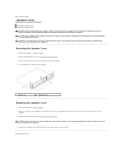
...yourself by using a wrist grounding strap or by your warranty. Remove the five screws that is not authorized by Dell™ is not covered by periodically touching an unpainted metal surface (such as a connector on your computer). Align the screw holes on the computer, replace...servicing that secure the speaker cover to electrical outlets, and turn them on the computer. Back to Contents Page Speaker Cover Dell™ Inspiron™ One 19 Service Manual Removing the Speaker Cover Replacing the Speaker Cover WARNING: Before working inside your computer, read the safety information that...
...yourself by using a wrist grounding strap or by your warranty. Remove the five screws that is not authorized by Dell™ is not covered by periodically touching an unpainted metal surface (such as a connector on your computer). Align the screw holes on the computer, replace...servicing that secure the speaker cover to electrical outlets, and turn them on the computer. Back to Contents Page Speaker Cover Dell™ Inspiron™ One 19 Service Manual Removing the Speaker Cover Replacing the Speaker Cover WARNING: Before working inside your computer, read the safety information that...
Service Manual
Page 20
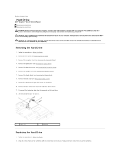
...). 5. Remove the speaker cover (see Removing the Computer Stand). 4. Remove the aluminum foil tapes that is not authorized by Dell™ is not covered by periodically touching an unpainted metal surface (such as a connector on your computer. Lift the hard drive out of the chassis. 1 screws .... For additional safety best practices information, see Removing the Back Cover). 9. Back to Contents Page Hard Drive Dell™ Inspiron™ One 19 Service Manual Removing the Hard Drive Replacing the Hard Drive WARNING: Before working inside your computer, read the safety...
...). 5. Remove the speaker cover (see Removing the Computer Stand). 4. Remove the aluminum foil tapes that is not authorized by Dell™ is not covered by periodically touching an unpainted metal surface (such as a connector on your computer. Lift the hard drive out of the chassis. 1 screws .... For additional safety best practices information, see Removing the Back Cover). 9. Back to Contents Page Hard Drive Dell™ Inspiron™ One 19 Service Manual Removing the Hard Drive Replacing the Hard Drive WARNING: Before working inside your computer, read the safety...
Service Manual
Page 21
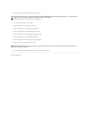
Replace the display bezel (see Replacing the Speaker Cover). 8. Replace the speaker cover (see Replacing the Display Bezel). 7. NOTE: Aluminum foil tapes will be shipped with the new hard drive. 4. CAUTION: Before turning on the hard drive. Back to the connector on the computer, replace all attached devices to the computer. 12. Affix the aluminum foil tapes on . Replace the back cover (see Replacing the Decorative Cover). 9. Replace the decorative cover (see Replacing the Back Cover). 6. CAUTION: Aluminum foil tapes are used for Electro Magnetic Induction (EMI) ...
Replace the display bezel (see Replacing the Speaker Cover). 8. Replace the speaker cover (see Replacing the Display Bezel). 7. NOTE: Aluminum foil tapes will be shipped with the new hard drive. 4. CAUTION: Before turning on the hard drive. Back to the connector on the computer, replace all attached devices to the computer. 12. Affix the aluminum foil tapes on . Replace the back cover (see Replacing the Decorative Cover). 9. Replace the decorative cover (see Replacing the Back Cover). 6. CAUTION: Aluminum foil tapes are used for Electro Magnetic Induction (EMI) ...
Service Manual
Page 22
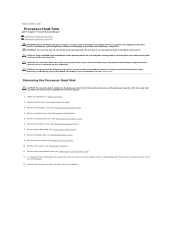
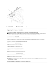
... cool before you are familiar with your computer. Removing the Processor Heat Sink CAUTION: To ensure maximum cooling for the processor, do not touch the heat transfer areas on your system board. Remove the I/O cover (see Removing the I /O Cover). 3. Remove the speaker cover... 1. For additional safety best practices information, see Removing the Optical Drive). 5. Back to Contents Page Processor Heat Sink Dell™ Inspiron™ One 19 Service Manual Removing the Processor Heat Sink Replacing the Processor Heat Sink WARNING: Before working inside your computer, read the ...
... cool before you are familiar with your computer. Removing the Processor Heat Sink CAUTION: To ensure maximum cooling for the processor, do not touch the heat transfer areas on your system board. Remove the I/O cover (see Removing the I /O Cover). 3. Remove the speaker cover... 1. For additional safety best practices information, see Removing the Optical Drive). 5. Back to Contents Page Processor Heat Sink Dell™ Inspiron™ One 19 Service Manual Removing the Processor Heat Sink Replacing the Processor Heat Sink WARNING: Before working inside your computer, read the ...
Service Manual
Page 23
Replace the system-board shield (see Replacing the Inverter). 6. Replace the inverter (see Replacing the System-Board Shield). 5. Replace the speaker cover (see Replacing the I /O bracket (see Replacing the Speaker Cover). 10. Follow the procedures in damage to the system board and processor. If either the processor or the processor heat sink is replaced, use the thermal grease provided in the kit to electrical outlets, and turn them on the system board and tighten the screws in ascending order. 4. Replace the I /O Bracket). 7. Replace the I /O Cover). Clean the ...
Replace the system-board shield (see Replacing the Inverter). 6. Replace the inverter (see Replacing the System-Board Shield). 5. Replace the speaker cover (see Replacing the I /O bracket (see Replacing the Speaker Cover). 10. Follow the procedures in damage to the system board and processor. If either the processor or the processor heat sink is replaced, use the thermal grease provided in the kit to electrical outlets, and turn them on the system board and tighten the screws in ascending order. 4. Replace the I /O Bracket). 7. Replace the I /O Cover). Clean the ...
