
Dell Inspiron 7000 Reference and Troubleshooting Guide
Page 32
...no user-selectable settings. 1.44 MB, 3 1/2" means there is no user-selectable settings. 2-4 Dell Inspiron 7000 Reference and Troubleshooting Guide Disabled indicates that a television is visible only on the computer's display (LCD Mode), only on an external monitor or projector (CRT Mode), or on self-test (POST) ... means that there is a diskette drive in the computer. When set to Enabled (the default), the diagnostic power-on both the display and an external device simultaneously (Simul Mode, the default). If you specify (usually the current time). Allows you cannot choose a boot...
...no user-selectable settings. 1.44 MB, 3 1/2" means there is no user-selectable settings. 2-4 Dell Inspiron 7000 Reference and Troubleshooting Guide Disabled indicates that a television is visible only on the computer's display (LCD Mode), only on an external monitor or projector (CRT Mode), or on self-test (POST) ... means that there is a diskette drive in the computer. When set to Enabled (the default), the diagnostic power-on both the display and an external device simultaneously (Simul Mode, the default). If you specify (usually the current time). Allows you cannot choose a boot...

Dell Inspiron 7000 Reference and Troubleshooting Guide
Page 74
... you can't find the message or beep code, respectively, along with its components. If the Video Display Device option is attached to LCD Mode? 6. Is the full display readable? Call Dell for technical assistance. (See Chapter 5, "Getting Help," for instructions.) No. The computer's video controller...on ? Is the display on the integrated keyboard several times. Turn off your computer and connect an external monitor to step 3. 3-28 Dell Inspiron 7000 Reference and Troubleshooting Guide Is the Video Display Device option in the Setup program set to LCD Mode, the computer ...
... you can't find the message or beep code, respectively, along with its components. If the Video Display Device option is attached to LCD Mode? 6. Is the full display readable? Call Dell for technical assistance. (See Chapter 5, "Getting Help," for instructions.) No. The computer's video controller...on ? Is the display on the integrated keyboard several times. Turn off your computer and connect an external monitor to step 3. 3-28 Dell Inspiron 7000 Reference and Troubleshooting Guide Is the Video Display Device option in the Setup program set to LCD Mode, the computer ...
Dell Inspiron 7000 Service Manual
Page 4
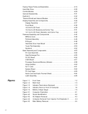
... Indicator Panel on Front of Computer 1-4 Battery Charge Gauge 1-5 Computer Orientation 4-1 Screw Identification 4-2 AC Adapter Removal 4-3 Computer Removal From Inspiron Port Replicator II 4-4 Main Battery Removal 4-4 vi Figure 4-4. Figure 4-5. Figure 1-5. Figure 4-2. Factory Repair Parts and Assemblies 4-15 Hard-...Keyboard 4-32 Thermal Shield and Internal Modem 4-34 Display Assembly and Components 4-36 Display Assembly 4-37 Front Bezel 4-38 13.3-Inch LCD Panel 4-39 13.3-Inch LCD Brackets and Carrier Tray 4-41 14.1-Inch LCD Panel, Brackets, and Carrier Tray 4-42 Palmrest...
... Indicator Panel on Front of Computer 1-4 Battery Charge Gauge 1-5 Computer Orientation 4-1 Screw Identification 4-2 AC Adapter Removal 4-3 Computer Removal From Inspiron Port Replicator II 4-4 Main Battery Removal 4-4 vi Figure 4-4. Figure 4-5. Figure 1-5. Figure 4-2. Factory Repair Parts and Assemblies 4-15 Hard-...Keyboard 4-32 Thermal Shield and Internal Modem 4-34 Display Assembly and Components 4-36 Display Assembly 4-37 Front Bezel 4-38 13.3-Inch LCD Panel 4-39 13.3-Inch LCD Brackets and Carrier Tray 4-41 14.1-Inch LCD Panel, Brackets, and Carrier Tray 4-42 Palmrest...

Dell Inspiron 7000 Service Manual
Page 5
...Combo Module or Secondary Battery Removal 4-8 Releasing a ZIF Connector 4-9 Exploded View-Computer 4-10 Exploded View-13.3-Inch Display Assembly 4-11 Exploded View-14.1-Inch Display Assembly 4-12 Exploded View-Palmrest Assembly 4-13 Exploded View-Base Assembly 4-14 Hard-Disk Drive Disassembly 4-28 CD-ROM... Removal 4-32 Thermal Shield Removal 4-34 Modem Removal 4-35 Display Assembly Removal 4-37 Front Bezel Removal 4-38 13.3-Inch LCD Panel Removal 4-39 13.3-Inch LCD Brackets and Carrier Tray Removal 4-41 14.1-Inch LCD Panel Removal 4-42 MPEG-2 Card Removal 4-45 Palmrest Assembly ...
...Combo Module or Secondary Battery Removal 4-8 Releasing a ZIF Connector 4-9 Exploded View-Computer 4-10 Exploded View-13.3-Inch Display Assembly 4-11 Exploded View-14.1-Inch Display Assembly 4-12 Exploded View-Palmrest Assembly 4-13 Exploded View-Base Assembly 4-14 Hard-Disk Drive Disassembly 4-28 CD-ROM... Removal 4-32 Thermal Shield Removal 4-34 Modem Removal 4-35 Display Assembly Removal 4-37 Front Bezel Removal 4-38 13.3-Inch LCD Panel Removal 4-39 13.3-Inch LCD Brackets and Carrier Tray Removal 4-41 14.1-Inch LCD Panel Removal 4-42 MPEG-2 Card Removal 4-45 Palmrest Assembly ...

Dell Inspiron 7000 Service Manual
Page 9
...the microprocessor (266 for 266 MHz or 300 for 300 MHz), the size (X for 13.3-inch LCD or G for 14.1-inch LCD) of the display, and the type (T for headphones, line-in speakers; The Inspiron 7000 D266GT contains a Pentium II microprocessor with MMX technology 300 MHz and a 14.1-in. XGA active-... the Dell Inspiron 7000 computers include the following new and/or advanced features: A minimum of 32 MB of SDRAM on the Inspiron 7000 D266GT and D300GT. 65-WH smart lithium ion battery (12 cells). 512-KB SRAM level-2 external cache and 32-KB internal cache. a 14.1-inch active-matrix XGA display on ...
...the microprocessor (266 for 266 MHz or 300 for 300 MHz), the size (X for 13.3-inch LCD or G for 14.1-inch LCD) of the display, and the type (T for headphones, line-in speakers; The Inspiron 7000 D266GT contains a Pentium II microprocessor with MMX technology 300 MHz and a 14.1-in. XGA active-... the Dell Inspiron 7000 computers include the following new and/or advanced features: A minimum of 32 MB of SDRAM on the Inspiron 7000 D266GT and D300GT. 65-WH smart lithium ion battery (12 cells). 512-KB SRAM level-2 external cache and 32-KB internal cache. a 14.1-inch active-matrix XGA display on ...
Dell Inspiron 7000 Service Manual
Page 25
... the computer is free of any obvious physical damage and that its cable, and connectors are not damaged, and then reinstall the modules. 9. Raise the LCD display and verify that the connectors on the modules and in the docu- Verify that the keyboard is free of any obvious physical damage. c. b. 8. The monitor...
... the computer is free of any obvious physical damage and that its cable, and connectors are not damaged, and then reinstall the modules. 9. Raise the LCD display and verify that the connectors on the modules and in the docu- Verify that the keyboard is free of any obvious physical damage. c. b. 8. The monitor...

Dell Inspiron 7000 Service Manual
Page 51
...,LG Front Bezel BZL,PLSTC,LCD,13.3,NBK,I7000 Display Hinge HNG,MET,LCD,I7000 Display Back Cover CVR,BK,LCD,13.3,I7000 Display Upper Rubber Bumper BMPR,RBR,UPR,LCD,I7000 Display Lower Rubber Bumper BMPR,RBR,LWR,LCD,I7000 LCD Flex Cable Assembly CBL,FLEX,LCD,13.3,I7000,LG LCD Shielding, behind panel SHLD,EMI,LCD,13.3,NBK,I7000 Removing and...
...,LG Front Bezel BZL,PLSTC,LCD,13.3,NBK,I7000 Display Hinge HNG,MET,LCD,I7000 Display Back Cover CVR,BK,LCD,13.3,I7000 Display Upper Rubber Bumper BMPR,RBR,UPR,LCD,I7000 Display Lower Rubber Bumper BMPR,RBR,LWR,LCD,I7000 LCD Flex Cable Assembly CBL,FLEX,LCD,13.3,I7000,LG LCD Shielding, behind panel SHLD,EMI,LCD,13.3,NBK,I7000 Removing and...

Dell Inspiron 7000 Service Manual
Page 61
... Floppy Disk-Drive Assembly ASSY,FD,1.44M,11MM,COMBO,I7000 DVD-ROM Assembly ASSY,DVD,17G,2X,INT,MKE,I7000 Display Assembly, 13.3" ASSY,LCD,XGA,13.3,I7000,LG Display Assembly, 14.1" ASSY,LCD,XGA,14.1,I7000,LG System Board Assembly ASSY,SYS,PLN,I7000 Bottom Plastic Assembly ASSY,CVR,BTM,PLSTC,I7000 Palmrest...
... Floppy Disk-Drive Assembly ASSY,FD,1.44M,11MM,COMBO,I7000 DVD-ROM Assembly ASSY,DVD,17G,2X,INT,MKE,I7000 Display Assembly, 13.3" ASSY,LCD,XGA,13.3,I7000,LG Display Assembly, 14.1" ASSY,LCD,XGA,14.1,I7000,LG System Board Assembly ASSY,SYS,PLN,I7000 Bottom Plastic Assembly ASSY,CVR,BTM,PLSTC,I7000 Palmrest...

Dell Inspiron 7000 Service Manual
Page 65
The Inspiron 7000 computer contains many screws of the screws, use a tackle or pill box as a storage device. Video card (Figure 4-10): 2X K-head, M2x3L Thermal shield (Figure 4-22): Hard-disk drive (Figure 4-18): 4X K-head M3x3L Display assembly (..., M2.5x6L 4X binding head, M2.5x6L 8X binding head, M2.5x6L Inverter board (Figure 4-26, 4-28): LCD panel (14.1") (Figure 4-28): Palmrest assembly (Figure 4-30): 4X binding head, M2.5x6L 1X K-head, M2... To help keep track of various sizes. Dell suggests a soft padded work surface and the plastic case. Removing and Replacing Parts 4-31
The Inspiron 7000 computer contains many screws of the screws, use a tackle or pill box as a storage device. Video card (Figure 4-10): 2X K-head, M2x3L Thermal shield (Figure 4-22): Hard-disk drive (Figure 4-18): 4X K-head M3x3L Display assembly (..., M2.5x6L 4X binding head, M2.5x6L 8X binding head, M2.5x6L Inverter board (Figure 4-26, 4-28): LCD panel (14.1") (Figure 4-28): Palmrest assembly (Figure 4-30): 4X binding head, M2.5x6L 1X K-head, M2... To help keep track of various sizes. Dell suggests a soft padded work surface and the plastic case. Removing and Replacing Parts 4-31

Dell Inspiron 7000 Service Manual
Page 70
The display assembly consists of the display assembly. This section describes how to remove the display assemblies shown in Figures 4-14 and 4-15 and gives removal and replacement procedures for the components of the following components: Front bezel LCD panel and hinges LCD brackets Carrier tray Inverter board Back cover 4-36
The display assembly consists of the display assembly. This section describes how to remove the display assemblies shown in Figures 4-14 and 4-15 and gives removal and replacement procedures for the components of the following components: Front bezel LCD panel and hinges LCD brackets Carrier tray Inverter board Back cover 4-36

Dell Inspiron 7000 Service Manual
Page 71
...steps (see Figure 4-24): 1. To remove the display assembly from connector JP3. Removing and Replacing Parts 4-37 This section provides the removal procedure for the display assembly. 6-mm screws (4) hinges (2) hinge saddles (2) LCD wire harness connector JP3 This procedure assumes that secure ...the two hinges. 4. Close the display. 3. Remove the four 6-mm screws that you have removed...
...steps (see Figure 4-24): 1. To remove the display assembly from connector JP3. Removing and Replacing Parts 4-37 This section provides the removal procedure for the display assembly. 6-mm screws (4) hinges (2) hinge saddles (2) LCD wire harness connector JP3 This procedure assumes that secure ...the two hinges. 4. Close the display. 3. Remove the four 6-mm screws that you have removed...

Dell Inspiron 7000 Service Manual
Page 72
... This section provides the removal procedure for the front bezel. 6-mm screws (4) rubber bumpers (2) front bezel rubber screw covers (2) This procedure assumes that the LCD wire harness is routed correctly through the openings in , and then lift upward to pry the rubber screw covers off of the bottom two screws... pick to free the snaps. Start at the middle bottom and then work around. Roll the plastic up slightly to insert your fingers between the LCD panel and the bezel. To remove the front bezel, follow these steps (see Figure 4-25): 1. When replacing the bezel, ensure that you ...
... This section provides the removal procedure for the front bezel. 6-mm screws (4) rubber bumpers (2) front bezel rubber screw covers (2) This procedure assumes that the LCD wire harness is routed correctly through the openings in , and then lift upward to pry the rubber screw covers off of the bottom two screws... pick to free the snaps. Start at the middle bottom and then work around. Roll the plastic up slightly to insert your fingers between the LCD panel and the bezel. To remove the front bezel, follow these steps (see Figure 4-25): 1. When replacing the bezel, ensure that you ...

Dell Inspiron 7000 Service Manual
Page 76
... inverter board as one unit out of inverter board. 3. This section provides the removal procedure for the LCD panel, LCD brackets, and carrier tray for the 14.1-inch display assembly. 6-mm screws (8) 4-mm screws (4) LCD brackets (2) LCD panel LCD wire harness interposer board CCFL cable carrier tray hinges (2) inverter board shield 3-mm screw inverter board back...
... inverter board as one unit out of inverter board. 3. This section provides the removal procedure for the LCD panel, LCD brackets, and carrier tray for the 14.1-inch display assembly. 6-mm screws (8) 4-mm screws (4) LCD brackets (2) LCD panel LCD wire harness interposer board CCFL cable carrier tray hinges (2) inverter board shield 3-mm screw inverter board back...

Dell Inspiron 7000 Service Manual
Page 101
..., 4-8 removal, 4-8 DC-DC board removal, 4-56 Diagnostics Menu, 3-5 diskette drive disassembly, 4-30 location (options bay), 1-2 display close/suspend button, 1-2 latch, 1-2 location, 1-2 display assembly 13.1-inch LCD panel removal, 4-39 13.3-inch exploded view, 4-11 14.1-inch exploded view, 4-12 14.1-inch... LCD panel removal, 4-42 carrier tray removal, 4-41 front bezel removal, 4-38 LCD bracket removal, 4-41 location, 4-36 removal,...
..., 4-8 removal, 4-8 DC-DC board removal, 4-56 Diagnostics Menu, 3-5 diskette drive disassembly, 4-30 location (options bay), 1-2 display close/suspend button, 1-2 latch, 1-2 location, 1-2 display assembly 13.1-inch LCD panel removal, 4-39 13.3-inch exploded view, 4-11 14.1-inch exploded view, 4-12 14.1-inch... LCD panel removal, 4-42 carrier tray removal, 4-41 front bezel removal, 4-38 LCD bracket removal, 4-41 location, 4-36 removal,...

