Service Manual
Page 3
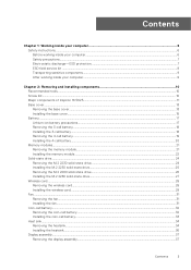
... instructions...6 Before working inside your computer...6 Safety precautions...7 Electrostatic discharge-ESD protection...7 ESD field service kit ...8 Transporting sensitive components...9 After working inside your computer...9 Chapter 2: Removing and installing components 10 Recommended tools...10 Screw list...10 Major components of Inspiron 16 5625...11 Base cover...13 Removing the base cover...13 Installing the base cover...15 Battery...17 Lithium-ion battery precautions...17 Removing the 3-cell battery...18 Installing the...
... instructions...6 Before working inside your computer...6 Safety precautions...7 Electrostatic discharge-ESD protection...7 ESD field service kit ...8 Transporting sensitive components...9 After working inside your computer...9 Chapter 2: Removing and installing components 10 Recommended tools...10 Screw list...10 Major components of Inspiron 16 5625...11 Base cover...13 Removing the base cover...13 Installing the base cover...15 Battery...17 Lithium-ion battery precautions...17 Removing the 3-cell battery...18 Installing the...

Service Manual
Page 4
... Entering BIOS setup program...59 Navigation keys...59 One time boot menu...60 System setup options...60 System and setup password...65 Assigning a system setup password...65 Deleting or changing an existing system setup password 66 Clearing CMOS settings...66 Clearing BIOS (System Setup) and System passwords 66 Updating the BIOS...67 Updating the BIOS in Windows...67 Updating the BIOS using the USB drive in Windows 67 Updating the BIOS from the F12 One-Time boot menu 68 Chapter 5: Troubleshooting...69 Handling swollen Lithium-ion batteries...69 Locate the Service...
... Entering BIOS setup program...59 Navigation keys...59 One time boot menu...60 System setup options...60 System and setup password...65 Assigning a system setup password...65 Deleting or changing an existing system setup password 66 Clearing CMOS settings...66 Clearing BIOS (System Setup) and System passwords 66 Updating the BIOS...67 Updating the BIOS in Windows...67 Updating the BIOS using the USB drive in Windows 67 Updating the BIOS from the F12 One-Time boot menu 68 Chapter 5: Troubleshooting...69 Handling swollen Lithium-ion batteries...69 Locate the Service...
Service Manual
Page 7
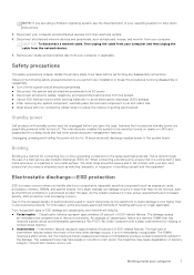
... taken before you open the case. The wrist strap should discharge residual power in the meantime may not be unplugged before performing any media card and optical disc from the system. ● Use an ESD field service kit when working inside your computer 7 Very slight charges can damage circuits in previous Dell products. As the industry pushes for connecting two or...
... taken before you open the case. The wrist strap should discharge residual power in the meantime may not be unplugged before performing any media card and optical disc from the system. ● Use an ESD field service kit when working inside your computer 7 Very slight charges can damage circuits in previous Dell products. As the industry pushes for connecting two or...
Service Manual
Page 11
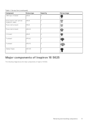
Screw list (continued) Component Screw type USB Type-C bracket M2x4 Power button with optional fingerprint reader Power-button board Power-button board M2x3 M2x3 M2x1.8 I/O board Touchpad M2x3 M1.6x2 Touchpad M2x1.8 Display hinges M2.5x5 Quantity 2 1 1 1 2 3 2 5 Screw image Major components of Inspiron 16 5625 The following image shows the major components of Inspiron 16 5625. Removing and installing components 11 Table 1.
Screw list (continued) Component Screw type USB Type-C bracket M2x4 Power button with optional fingerprint reader Power-button board Power-button board M2x3 M2x3 M2x1.8 I/O board Touchpad M2x3 M1.6x2 Touchpad M2x1.8 Display hinges M2.5x5 Quantity 2 1 1 1 2 3 2 5 Screw image Major components of Inspiron 16 5625 The following image shows the major components of Inspiron 16 5625. Removing and installing components 11 Table 1.

Service Manual
Page 17
... After working inside your computer. Removing and installing components 17 Next steps 1. Place and snap the base cover into place on the base cover. 4. In such an instance, contact Dell technical support for assistance. Disconnect the AC power adapter from the system and operate the computer solely on battery power-the battery is fully discharged when the computer no longer turns on when the power button...
... After working inside your computer. Removing and installing components 17 Next steps 1. Place and snap the base cover into place on the base cover. 4. In such an instance, contact Dell technical support for assistance. Disconnect the AC power adapter from the system and operate the computer solely on battery power-the battery is fully discharged when the computer no longer turns on when the power button...

Service Manual
Page 36
... are replacing a component, remove the existing component before performing the installation process. NOTE: The number of the installation procedure. The following image(s) indicate the location of the heatsink and provides a visual representation of screws on the heat sink varies depending on the graphic card configuration ordered. About this task NOTE: If either the system board or the heat sink is replaced, use the...
... are replacing a component, remove the existing component before performing the installation process. NOTE: The number of the installation procedure. The following image(s) indicate the location of the heatsink and provides a visual representation of screws on the heat sink varies depending on the graphic card configuration ordered. About this task NOTE: If either the system board or the heat sink is replaced, use the...
Service Manual
Page 40
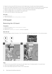
... keyboard assembly. 8. Replace the display cable to the palm-rest and keyboard assembly. 7. Connect the display cable to the palm-rest and keyboard assembly. 5. Steps 1. I/O board Removing the I /O-board cable. 40 Removing and installing components Follow the procedure in After working inside your computer. 2. Remove the 3-cell battery or 4-cell battery, whichever is applicable. Next steps 1. 4. Replace the three screws (M2.5x5) that secure the right display hinge to the routing guides...
... keyboard assembly. 8. Replace the display cable to the palm-rest and keyboard assembly. 7. Connect the display cable to the palm-rest and keyboard assembly. 5. Steps 1. I/O board Removing the I /O-board cable. 40 Removing and installing components Follow the procedure in After working inside your computer. 2. Remove the 3-cell battery or 4-cell battery, whichever is applicable. Next steps 1. 4. Replace the three screws (M2.5x5) that secure the right display hinge to the routing guides...
Service Manual
Page 46
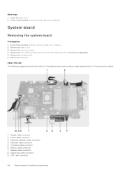
... location of the system board and provides a visual representation of the removal procedure. 1. Speaker-cable connector 8. Remove the M.2 2230 solid-state drive or M.2 2280 solid-state drive, whichever is applicable. 5. Display-cable connector 2. Next steps 1. Install the base cover. 2. Follow the procedure in After working inside your computer. 2. Touchpad-cable connector 6. Follow the procedure in Before working inside your computer. Remove the memory module. 4. Remove the wireless card. 6. System fan-cable connector 9. SSD-1 slot...
... location of the system board and provides a visual representation of the removal procedure. 1. Speaker-cable connector 8. Remove the M.2 2230 solid-state drive or M.2 2280 solid-state drive, whichever is applicable. 5. Display-cable connector 2. Next steps 1. Install the base cover. 2. Follow the procedure in After working inside your computer. 2. Touchpad-cable connector 6. Follow the procedure in Before working inside your computer. Remove the memory module. 4. Remove the wireless card. 6. System fan-cable connector 9. SSD-1 slot...
Service Manual
Page 50
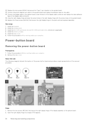
... wireless card. 3. 12. Remove the base cover. Connect the power-adapter port cable to the palm-rest and keyboard assembly. Install the memory module. 5. Follow the procedure in Before working inside your computer. About this task The following image(s) indicate the location of the power-button board and provides a visual representation of 90 degrees. 50 Removing and installing components Replace the three screws (M2.5x5) that secure the Type-C port-bracket to the system board. 2. Open...
... wireless card. 3. 12. Remove the base cover. Connect the power-adapter port cable to the palm-rest and keyboard assembly. Install the memory module. 5. Follow the procedure in Before working inside your computer. About this task The following image(s) indicate the location of the power-button board and provides a visual representation of 90 degrees. 50 Removing and installing components Replace the three screws (M2.5x5) that secure the Type-C port-bracket to the system board. 2. Open...

Service Manual
Page 55
... system board. 6. Install the base cover. 2. Follow the procedure in After working inside your computer. 2. Remove the wireless card. 6. Remove the display assembly. 8. Remove the power-button board. 13. Steps 1. Remove the coin-cell battery. 10. Remove the I/O board. 11. Close the left display hinge and align the screw holes on the left display hinge to the system board. 4. Remove the power button. 12. Removing and installing components 55 Remove the memory module. 4. Connect the power-adapter port cable to the system board. Replace the...
... system board. 6. Install the base cover. 2. Follow the procedure in After working inside your computer. 2. Remove the wireless card. 6. Remove the display assembly. 8. Remove the power-button board. 13. Steps 1. Remove the coin-cell battery. 10. Remove the I/O board. 11. Close the left display hinge and align the screw holes on the left display hinge to the system board. 4. Remove the power button. 12. Removing and installing components 55 Remove the memory module. 4. Connect the power-adapter port cable to the system board. Replace the...

Service Manual
Page 59
... the amount of RAM and the size of the hard drive. ● Change the system configuration information. ● Set or change the settings in the BIOS Setup program. Press F2 immediately to the next field. Table 3. Moves to enter the BIOS setup program. Moves to the previous field. BIOS overview The BIOS manages data flow between the computer's operating system and attached devices such as hard disk, video adapter, keyboard, mouse, and printer. NOTE...
... the amount of RAM and the size of the hard drive. ● Change the system configuration information. ● Set or change the settings in the BIOS Setup program. Press F2 immediately to the next field. Table 3. Moves to enter the BIOS setup program. Moves to the previous field. BIOS overview The BIOS manages data flow between the computer's operating system and attached devices such as hard disk, video adapter, keyboard, mouse, and printer. NOTE...

Service Manual
Page 62
... setup options-Advance menu (continued) Advance Power Option Power on LID open action. Options are : ● Disabled ● Enabled (Default) Allows to permanently turn off/turn-on /switch-off the External USB ports in the Operating System. Options are : ● Enabled (Default) ● Disabled Performs auto firmware reset when corrupted BIOS is detected. Options are from Hard Drive BIOS Auto Recovery SupportAssist System Resolution Auto OS Recovery Threshold Support Assist OS Recovery Keyboard Illumination Keyboard Backlight with Battery Allows to Switch-on the Keyboard...
... setup options-Advance menu (continued) Advance Power Option Power on LID open action. Options are : ● Disabled ● Enabled (Default) Allows to permanently turn off/turn-on /switch-off the External USB ports in the Operating System. Options are : ● Enabled (Default) ● Disabled Performs auto firmware reset when corrupted BIOS is detected. Options are from Hard Drive BIOS Auto Recovery SupportAssist System Resolution Auto OS Recovery Threshold Support Assist OS Recovery Keyboard Illumination Keyboard Backlight with Battery Allows to Switch-on the Keyboard...
Service Manual
Page 63
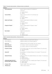
... allow User to Switch-on /switch-off the Wireless Card. The options are : ● Activate ● Deactivate Displays the Status of the Absolute Module on the computer. The options are : ● Enabled (Default) ● Disabled Media Card Reader Allows to edit the Asset Tag of the computer password. Set, change , or delete the administrator password. Asset Tag Admin Password System Password Displays and allows to enable/disable the Media Card reader. TPM 2.0 Security options. Options are : ● Disable (Default) ● Reboot Bypass Enable or disable...
... allow User to Switch-on /switch-off the Wireless Card. The options are : ● Activate ● Deactivate Displays the Status of the Absolute Module on the computer. The options are : ● Enabled (Default) ● Disabled Media Card Reader Allows to edit the Asset Tag of the computer password. Set, change , or delete the administrator password. Asset Tag Admin Password System Password Displays and allows to enable/disable the Media Card reader. TPM 2.0 Security options. Options are : ● Disable (Default) ● Reboot Bypass Enable or disable...

Service Manual
Page 66
... www.dell.com/contactdell. If you change the System and/or Setup password, reenter the new password when prompted. Replace the base cover. 7. Type the system password that the Password Status is Unlocked. 3. The System Security screen is Locked. In the System Security screen, verify that the battery cable has been disconnected from the system board. 3. Clearing CMOS settings About this task CAUTION: Clearing CMOS settings will reset the BIOS settings on your application. 66 BIOS setup Ensure that Password...
... www.dell.com/contactdell. If you change the System and/or Setup password, reenter the new password when prompted. Replace the base cover. 7. Type the system password that the Password Status is Unlocked. 3. The System Security screen is Locked. In the System Security screen, verify that the battery cable has been disconnected from the system board. 3. Clearing CMOS settings About this task CAUTION: Clearing CMOS settings will reset the BIOS settings on your application. 66 BIOS setup Ensure that Password...
Service Manual
Page 68
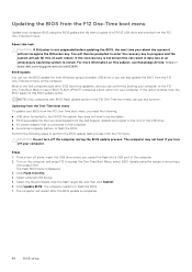
... One-Time Boot Menu to a FAT32 USB drive and booting from file. 4. Turn on each reboot. Select the file and double-click the flash target file, and then click Submit. 6. The computer restarts to access the One-Time Boot Menu, select BIOS Update using the mouse or arrow keys then press Enter. Click Flash from the F12 One-Time boot menu. Select external USB device. 5. Updating from the One-Time boot menu To update your BIOS from the...
... One-Time Boot Menu to a FAT32 USB drive and booting from file. 4. Turn on each reboot. Select the file and double-click the flash target file, and then click Submit. 6. The computer restarts to access the One-Time Boot Menu, select BIOS Update using the mouse or arrow keys then press Enter. Click Flash from the F12 One-Time boot menu. Select external USB device. 5. Updating from the One-Time boot menu To update your BIOS from the...

Service Manual
Page 71
...-Caps Lock disabled. Diagnostic-light LED codes (continued) Diagnostic light codes (Amber,White) Problem description 4,1 Memory error 4,2 Power rail error Camera status light: Indicates whether the camera is in use . Dell SupportAssist OS Recovery is launched by one of your computer when it automatically starts Dell SupportAssist OS Recovery. You can be initiated by the BIOS internally. Click SupportAssist and then, click SupportAssist OS Recovery. This diagnostic is unable to boot to its factory state. Caps Lock status light: Indicates...
...-Caps Lock disabled. Diagnostic-light LED codes (continued) Diagnostic light codes (Amber,White) Problem description 4,1 Memory error 4,2 Power rail error Camera status light: Indicates whether the camera is in use . Dell SupportAssist OS Recovery is launched by one of your computer when it automatically starts Dell SupportAssist OS Recovery. You can be initiated by the BIOS internally. Click SupportAssist and then, click SupportAssist OS Recovery. This diagnostic is unable to boot to its factory state. Caps Lock status light: Indicates...
Service Manual
Page 72
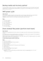
.... 8. Dell proposes multiple options for recovering Windows operating system on your computer. 2. Connect the power adapter to conduct a WiFi power cycle: NOTE: Some ISPs (Internet Service Providers) provide a modem/router combo device. The following procedure provides the instructions on the wireless router. 6. Turn on your computer does not power on the modem. 7. For more information about performing a hard reset, see Dell Windows Backup Media and Recovery Options. Remove the battery. 5. Backup media and recovery options It is removed. Press and hold the power button...
.... 8. Dell proposes multiple options for recovering Windows operating system on your computer. 2. Connect the power adapter to conduct a WiFi power cycle: NOTE: Some ISPs (Internet Service Providers) provide a modem/router combo device. The following procedure provides the instructions on the wireless router. 6. Turn on your computer does not power on the modem. 7. For more information about performing a hard reset, see Dell Windows Backup Media and Recovery Options. Remove the battery. 5. Backup media and recovery options It is removed. Press and hold the power button...

Setup and Specifications
Page 4
... power button. NOTE: The battery may differ from the Windows Start menu-Recommended. 1 Set up your Inspiron 16 5625 NOTE: The images in with or create a Microsoft account. Follow the on for the wireless network access when prompted. ● If connected to the Internet, create an offline account. ● On the Support and Protection screen, enter your computer when it is turned on -screen instructions to complete the setup. When setting up, Dell recommends that the power adapter...
... power button. NOTE: The battery may differ from the Windows Start menu-Recommended. 1 Set up your Inspiron 16 5625 NOTE: The images in with or create a Microsoft account. Follow the on for the wireless network access when prompted. ● If connected to the Internet, create an offline account. ● On the Support and Protection screen, enter your computer when it is turned on -screen instructions to complete the setup. When setting up, Dell recommends that the power adapter...
Setup and Specifications
Page 6
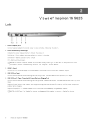
... displays. Supports Power Delivery that enables faster charging. NOTE: A USB Type-C to DisplayPort adapter (sold separately) is low or critical. Provides video and audio output. 4. Power and battery-status light Indicates the power state and battery state of Inspiron 16 5625 2 Views of up to 5 Gbps. 5. Solid amber-Battery charge is required to connect a DisplayPort device. 6 Views of the computer. HDMI 1.4 port Connect to a TV, external display or another HDMI-in your computer and charge the battery. 2. Provides up to connect an external display using a display...
... displays. Supports Power Delivery that enables faster charging. NOTE: A USB Type-C to DisplayPort adapter (sold separately) is low or critical. Provides video and audio output. 4. Power and battery-status light Indicates the power state and battery state of Inspiron 16 5625 2 Views of up to 5 Gbps. 5. Solid amber-Battery charge is required to connect a DisplayPort device. 6 Views of the computer. HDMI 1.4 port Connect to a TV, external display or another HDMI-in your computer and charge the battery. 2. Provides up to connect an external display using a display...
Setup and Specifications
Page 12
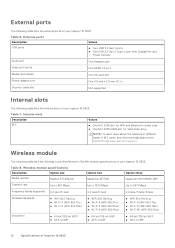
... types of Inspiron 16 5625 Table 7. External ports Description USB ports Values ● Two USB 3.2 Gen 1 ports ● One USB 3.2 Gen 2 Type-C port with DisplayPort and Power Delivery Audio port One Headset jack Video port/ports One HDMI 1.4 port Media-card reader One SD-card slot Power-adapter port One 4.5 mm x 2.9 mm DC-in Security-cable slot Not supported Internal slots The following table lists the internal slots of your Inspiron 16 5625. Wireless module The following table lists the Wireless Local Area Network (WLAN) module specifications of your Inspiron 16 5625...
... types of Inspiron 16 5625 Table 7. External ports Description USB ports Values ● Two USB 3.2 Gen 1 ports ● One USB 3.2 Gen 2 Type-C port with DisplayPort and Power Delivery Audio port One Headset jack Video port/ports One HDMI 1.4 port Media-card reader One SD-card slot Power-adapter port One 4.5 mm x 2.9 mm DC-in Security-cable slot Not supported Internal slots The following table lists the internal slots of your Inspiron 16 5625. Wireless module The following table lists the Wireless Local Area Network (WLAN) module specifications of your Inspiron 16 5625...


