Service Manual
Page 4
Replacing the Memory Module(s 20 6 Optical Drive 23 Removing the Optical Drive 23 Replacing the Optical Drive 24 7 Keyboard 27 Removing the Keyboard 27 Replacing the Keyboard 29 8 Palm-Rest Assembly 31 Removing the Palm-Rest Assembly 31 Replacing the Palm-Rest Assembly 34 9 Wireless Mini-Card(s 37 Removing the Mini-Card(s 37 Replacing the Mini-Card(s 39 10 Display 41 Display Assembly 41 Removing the Display Assembly 41 Replacing the Display Assembly 43 Display Bezel 44 4 Contents
Replacing the Memory Module(s 20 6 Optical Drive 23 Removing the Optical Drive 23 Replacing the Optical Drive 24 7 Keyboard 27 Removing the Keyboard 27 Replacing the Keyboard 29 8 Palm-Rest Assembly 31 Removing the Palm-Rest Assembly 31 Replacing the Palm-Rest Assembly 34 9 Wireless Mini-Card(s 37 Removing the Mini-Card(s 37 Replacing the Mini-Card(s 39 10 Display 41 Display Assembly 41 Removing the Display Assembly 41 Replacing the Display Assembly 43 Display Bezel 44 4 Contents

Service Manual
Page 5
Removing the Display Bezel 44 Replacing the Display Bezel 45 Display Panel 46 Removing the Display Panel 46 Replacing the Display Panel 47 Display Cable 48 Removing the Display Cable 48 Replacing the Display Cable 49 Display-Panel Brackets 50 Removing the Display-Panel Brackets 50 Replacing the Display-Panel Brackets 50 11 Hinge Cover 53 Removing the Hinge Cover 53 Replacing...
Removing the Display Bezel 44 Replacing the Display Bezel 45 Display Panel 46 Removing the Display Panel 46 Replacing the Display Panel 47 Display Cable 48 Removing the Display Cable 48 Replacing the Display Cable 49 Display-Panel Brackets 50 Removing the Display-Panel Brackets 50 Replacing the Display-Panel Brackets 50 11 Hinge Cover 53 Removing the Hinge Cover 53 Replacing...

Service Manual
Page 11
Before You Begin 11 CAUTION: To help prevent damage to the system board, remove the main battery (see "Removing the Battery" on page 15) before working inside the computer. 7 Remove the battery (see "Removing the Battery" on page 15). 8 Turn the computer top-side up, open the display, and press the power button to ground the system board.
Before You Begin 11 CAUTION: To help prevent damage to the system board, remove the main battery (see "Removing the Battery" on page 15) before working inside the computer. 7 Remove the battery (see "Removing the Battery" on page 15). 8 Turn the computer top-side up, open the display, and press the power button to ground the system board.

Service Manual
Page 13
...Top Cover 1 Follow the instructions in "Before You Begin" on page 9. 2 Press and hold the release button that is not authorized by Dell is not covered by periodically touching an unpainted metal surface (such as a connector on your computer. Top Cover 13 CAUTION: To avoid electrostatic... your computer. For additional safety best practices information, see "Removing the Battery" on your warranty. CAUTION: To help prevent damage to the display back cover. 3 Slide and lift the top cover. 2 Top Cover WARNING: Before working inside your computer, read the safety information that ...
...Top Cover 1 Follow the instructions in "Before You Begin" on page 9. 2 Press and hold the release button that is not authorized by Dell is not covered by periodically touching an unpainted metal surface (such as a connector on your computer. Top Cover 13 CAUTION: To avoid electrostatic... your computer. For additional safety best practices information, see "Removing the Battery" on your warranty. CAUTION: To help prevent damage to the display back cover. 3 Slide and lift the top cover. 2 Top Cover WARNING: Before working inside your computer, read the safety information that ...

Service Manual
Page 14
Failure to do so may result in "Before You Begin" on the computer, replace all screws and ensure that the DELL logo is facing towards the back of the computer while replacing the top cover. 2 Align the top cover to the computer. 14 Top Cover Ensure ... screws remain inside the computer. CAUTION: Before turning on page 9. 1 2 1 top cover 2 release button Replacing the Top Cover 1 Follow the instructions in damage to the display back cover. 3 Slide the top cover until it clicks into place. NOTE: Ensure that no gaps between the top cover and...
Failure to do so may result in "Before You Begin" on the computer, replace all screws and ensure that the DELL logo is facing towards the back of the computer while replacing the top cover. 2 Align the top cover to the computer. 14 Top Cover Ensure ... screws remain inside the computer. CAUTION: Before turning on page 9. 1 2 1 top cover 2 release button Replacing the Top Cover 1 Follow the instructions in damage to the display back cover. 3 Slide the top cover until it clicks into place. NOTE: Ensure that no gaps between the top cover and...

Service Manual
Page 27
... servicing that shipped with your computer. Be careful when removing and handling the keyboard. 3 Turn the computer over and open the display as far as a connector on page 15) before working inside the computer. CAUTION: To help prevent damage to replace. Removing ... system board, remove the main battery (see the Regulatory Compliance Homepage at dell.com/regulatory_compliance. 7 Keyboard WARNING: Before working inside your computer, read the safety information that is not authorized by Dell is not covered by periodically touching an unpainted metal surface (such as possible...
... servicing that shipped with your computer. Be careful when removing and handling the keyboard. 3 Turn the computer over and open the display as far as a connector on page 15) before working inside the computer. CAUTION: To help prevent damage to replace. Removing ... system board, remove the main battery (see the Regulatory Compliance Homepage at dell.com/regulatory_compliance. 7 Keyboard WARNING: Before working inside your computer, read the safety information that is not authorized by Dell is not covered by periodically touching an unpainted metal surface (such as possible...

Service Manual
Page 28
Failure to do so could result in scratching the display panel. 6 Carefully turn the keyboard over and place it on the system board and remove the keyboard cable. 8 Lift the keyboard off the computer. 28 Keyboard CAUTION: Be extremely careful when removing and handling the keyboard. Be careful when removing and handling the keyboard. 1 2 1 plastic scribe 2 keyboard CAUTION: The keycaps on the keyboard are fragile, easily dislodged, and time-consuming to the connector on the palm rest assembly. 7 Lift the connector latch that secures the keyboard cable to replace.
Failure to do so could result in scratching the display panel. 6 Carefully turn the keyboard over and place it on the system board and remove the keyboard cable. 8 Lift the keyboard off the computer. 28 Keyboard CAUTION: Be extremely careful when removing and handling the keyboard. Be careful when removing and handling the keyboard. 1 2 1 plastic scribe 2 keyboard CAUTION: The keycaps on the keyboard are fragile, easily dislodged, and time-consuming to the connector on the palm rest assembly. 7 Lift the connector latch that secures the keyboard cable to replace.

Service Manual
Page 29
Keyboard 29 1 2 1 keyboard cable 2 keyboard-cable connector Replacing the Keyboard 1 Follow the instructions in "Before You Begin" on page 9. 2 Slide the keyboard cable into the connector on the system board and press down on the connector latch to secure the cable. 3 Slide the tabs on the keyboard into the slots on the palm-rest assembly and lower the keyboard into place. 4 Gently press around the edges of the keyboard and slide it upwards to secure the keyboard under the tabs on the palm rest. 5 Close the display and turn the computer over.
Keyboard 29 1 2 1 keyboard cable 2 keyboard-cable connector Replacing the Keyboard 1 Follow the instructions in "Before You Begin" on page 9. 2 Slide the keyboard cable into the connector on the system board and press down on the connector latch to secure the cable. 3 Slide the tabs on the keyboard into the slots on the palm-rest assembly and lower the keyboard into place. 4 Gently press around the edges of the keyboard and slide it upwards to secure the keyboard under the tabs on the palm rest. 5 Close the display and turn the computer over.
Service Manual
Page 32
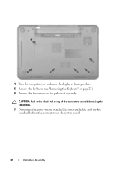
CAUTION: Pull on the plastic tab on top of the connectors to avoid damaging the connectors. 7 Disconnect the power-button board cable, touch-pad cable, and hot-key board cable from the connectors on the palm-rest assembly. 4 Turn the computer over and open the display as far as possible. 5 Remove the keyboard (see "Removing the Keyboard" on page 27). 6 Remove the four screws on the system board. 32 Palm-Rest Assembly
CAUTION: Pull on the plastic tab on top of the connectors to avoid damaging the connectors. 7 Disconnect the power-button board cable, touch-pad cable, and hot-key board cable from the connectors on the palm-rest assembly. 4 Turn the computer over and open the display as far as possible. 5 Remove the keyboard (see "Removing the Keyboard" on page 27). 6 Remove the four screws on the system board. 32 Palm-Rest Assembly

Service Manual
Page 35
6 Close the display and turn the computer over. 7 Replace the six screws that secure the palm-rest assembly to the computer. Palm-Rest Assembly 35 CAUTION: Before turning on page 16). Failure to do so may result in damage to the computer base. 8 Replace the battery (see "Replacing the Battery" on the computer, replace all screws and ensure that no stray screws remain inside the computer.
6 Close the display and turn the computer over. 7 Replace the six screws that secure the palm-rest assembly to the computer. Palm-Rest Assembly 35 CAUTION: Before turning on page 16). Failure to do so may result in damage to the computer base. 8 Replace the battery (see "Replacing the Battery" on the computer, replace all screws and ensure that no stray screws remain inside the computer.

Service Manual
Page 41
... avoid electrostatic discharge, ground yourself by using a wrist grounding strap or by your computer. Display 41 CAUTION: Only a certified service technician should perform repairs on your computer). Display Assembly Removing the Display Assembly 1 Follow the instructions in "Before You Begin" on page 9. 2 Remove the... that shipped with your warranty. Damage due to the computer base. 10 Display WARNING: Before working inside your computer, read the safety information that is not authorized by Dell is not covered by periodically touching an unpainted metal surface (such as a...
... avoid electrostatic discharge, ground yourself by using a wrist grounding strap or by your computer. Display 41 CAUTION: Only a certified service technician should perform repairs on your computer). Display Assembly Removing the Display Assembly 1 Follow the instructions in "Before You Begin" on page 9. 2 Remove the... that shipped with your warranty. Damage due to the computer base. 10 Display WARNING: Before working inside your computer, read the safety information that is not authorized by Dell is not covered by periodically touching an unpainted metal surface (such as a...

Service Manual
Page 42
... optional and may not be present in "Removing the Palm-Rest Assembly" on page 31. 5 Disconnect the display cable and touch-screen cable from the routing guides. 8 Remove the four screws that secure the display assembly to step 9 in your computer. 6 Disconnect the Mini-Card antenna cables from the connectors on the... the Mini-Card antenna cables and remove the cables from the system-board connectors. 4 Follow the instructions from step 3 to the computer base. 9 Lift the display assembly off the computer base. 42...
... optional and may not be present in "Removing the Palm-Rest Assembly" on page 31. 5 Disconnect the display cable and touch-screen cable from the routing guides. 8 Remove the four screws that secure the display assembly to step 9 in your computer. 6 Disconnect the Mini-Card antenna cables from the connectors on the... the Mini-Card antenna cables and remove the cables from the system-board connectors. 4 Follow the instructions from step 3 to the computer base. 9 Lift the display assembly off the computer base. 42...

Service Manual
Page 43
1 2 4 3 1 display assembly 3 display-cable connector 2 screws (4) 4 Mini-Card antenna cables (2) Replacing the Display Assembly 1 Follow the instructions in "Before You Begin" on page 9. 2 Place the display assembly in position and replace the four screws that secure the display assembly to the computer base. 3 Route the Mini-Card antenna cables through the routing guides. 4 Connect the Mini-Card antenna cables to the Mini-Card(s) (see "Replacing the Mini-Card(s)" on page 39). Display 43
1 2 4 3 1 display assembly 3 display-cable connector 2 screws (4) 4 Mini-Card antenna cables (2) Replacing the Display Assembly 1 Follow the instructions in "Before You Begin" on page 9. 2 Place the display assembly in position and replace the four screws that secure the display assembly to the computer base. 3 Route the Mini-Card antenna cables through the routing guides. 4 Connect the Mini-Card antenna cables to the Mini-Card(s) (see "Replacing the Mini-Card(s)" on page 39). Display 43

Service Manual
Page 44
... the Battery" on page 41). Be careful when removing it to prevent damaging the display bezel. 4 Using your fingertips, carefully pry up the inside the computer. CAUTION: The display bezel is extremely fragile. 5 Connect the display cable and touch-screen cable to the connectors on the system board. 6 Follow the...step 7 in "Replacing the Palm-Rest Assembly" on page 34. 7 Replace the two screws that no stray screws remain inside edge of the display bezel. 5 Remove the display bezel. 44 Display CAUTION: Before turning on the computer, replace all screws and ensure that secure the...
... the Battery" on page 41). Be careful when removing it to prevent damaging the display bezel. 4 Using your fingertips, carefully pry up the inside the computer. CAUTION: The display bezel is extremely fragile. 5 Connect the display cable and touch-screen cable to the connectors on the system board. 6 Follow the...step 7 in "Replacing the Palm-Rest Assembly" on page 34. 7 Replace the two screws that no stray screws remain inside edge of the display bezel. 5 Remove the display bezel. 44 Display CAUTION: Before turning on the computer, replace all screws and ensure that secure the...

Service Manual
Page 45
CAUTION: Before turning on page 14). Failure to the computer. Display 45 1 1 display bezel Replacing the Display Bezel 1 Follow the instructions in damage to do so may result in "Before You Begin" on page 9. 2 Realign the display bezel over the display panel and gently snap it into place. 3 Replace the display assembly (see "Replacing the Display Assembly" on page 43). 4 Replace the top cover (see "Replacing the Top Cover" on the computer, replace all screws and ensure that no stray screws remain inside the computer.
CAUTION: Before turning on page 14). Failure to the computer. Display 45 1 1 display bezel Replacing the Display Bezel 1 Follow the instructions in damage to do so may result in "Before You Begin" on page 9. 2 Realign the display bezel over the display panel and gently snap it into place. 3 Replace the display assembly (see "Replacing the Display Assembly" on page 43). 4 Replace the top cover (see "Replacing the Top Cover" on the computer, replace all screws and ensure that no stray screws remain inside the computer.

Service Manual
Page 46
Display Panel Removing the Display Panel 1 Follow the instructions in "Before You Begin" on page 9. 2 Remove the display assembly (see "Removing the Display Assembly" on page 41). 3 Remove the display bezel (see "Removing the Display Bezel" on page 44). 4 Disconnect the camera cable from the connector on the camera module. 1 1 camera module 5 Remove the eight screws that secure the display panel to the display back cover. 6 Lift the display panel off the display back cover. 46 Display
Display Panel Removing the Display Panel 1 Follow the instructions in "Before You Begin" on page 9. 2 Remove the display assembly (see "Removing the Display Assembly" on page 41). 3 Remove the display bezel (see "Removing the Display Bezel" on page 44). 4 Disconnect the camera cable from the connector on the camera module. 1 1 camera module 5 Remove the eight screws that secure the display panel to the display back cover. 6 Lift the display panel off the display back cover. 46 Display

Service Manual
Page 47
... routing and remove them from the routing guides on the display back cover. 8 Turn the display panel over and place it on a clean surface. 9 Remove the display cable (see "Removing the Display Cable" on page 48). 10 Remove the display-panel brackets (see "Replacing the Display Cable" on page 49). 4 Connect the camera cable to the...
... routing and remove them from the routing guides on the display back cover. 8 Turn the display panel over and place it on a clean surface. 9 Remove the display cable (see "Removing the Display Cable" on page 48). 10 Remove the display-panel brackets (see "Replacing the Display Cable" on page 49). 4 Connect the camera cable to the...

Service Manual
Page 48
.... 6 Align the screw holes on the display panel with the screw holes on the display back cover and replace the eight screws. 7 Replace the display bezel (see "Replacing the Display Bezel" on page 45). 8 Replace the display assembly (see "Removing the Display Panel" on page 43). CAUTION: Before...result in "Before You Begin" on page 9. 2 Remove the display assembly (see "Removing the Display Assembly" on page 41). 3 Remove the display bezel (see "Removing the Display Bezel" on page 44). 4 Remove the display panel (see "Replacing the Display Assembly" on page 46). 5 Lift the tape that no ...
.... 6 Align the screw holes on the display panel with the screw holes on the display back cover and replace the eight screws. 7 Replace the display bezel (see "Replacing the Display Bezel" on page 45). 8 Replace the display assembly (see "Removing the Display Panel" on page 43). CAUTION: Before...result in "Before You Begin" on page 9. 2 Remove the display assembly (see "Removing the Display Assembly" on page 41). 3 Remove the display bezel (see "Removing the Display Bezel" on page 44). 4 Remove the display panel (see "Replacing the Display Assembly" on page 46). 5 Lift the tape that no ...

Service Manual
Page 49
... turning on page 43). Display 49 1 2 1 display cable 2 tape Replacing the Display Cable 1 Follow the instructions in damage to the display-board connector and secure it with the tape. 3 Replace the display panel (see "Replacing the Display Panel" on page 47). 4 Replace the display bezel (see "Replacing the Display Bezel" on page 45). 5 Replace the display assembly (see "Replacing...
... turning on page 43). Display 49 1 2 1 display cable 2 tape Replacing the Display Cable 1 Follow the instructions in damage to the display-board connector and secure it with the tape. 3 Replace the display panel (see "Replacing the Display Panel" on page 47). 4 Replace the display bezel (see "Replacing the Display Bezel" on page 45). 5 Replace the display assembly (see "Replacing...

Service Manual
Page 50
... Brackets 1 Follow the instructions in "Before You Begin" on page 9. 2 Remove the display assembly (see "Removing the Display Assembly" on page 41). 3 Remove the display bezel (see "Removing the Display Bezel" on page 44). 4 Remove the display panel (see "Removing the Display Panel" on page 46). 5 Remove the four screws (two on each side) that secure...
... Brackets 1 Follow the instructions in "Before You Begin" on page 9. 2 Remove the display assembly (see "Removing the Display Assembly" on page 41). 3 Remove the display bezel (see "Removing the Display Bezel" on page 44). 4 Remove the display panel (see "Removing the Display Panel" on page 46). 5 Remove the four screws (two on each side) that secure...


