Owners Manual
Page 3
Contents Before Working Inside Your Computer 10 Before You Begin 10 Safety Instructions 10 Recommended Tools 11 After Working Inside Your Computer 12 Removing the Battery 13 Procedure...13 Replacing the Battery 14 Procedure...14 Removing the Base Cover 15 Prerequisites...15 Procedure...15 Replacing the Base Cover 16 Procedure...16 Post-requisites 16 Removing the Optical Drive 17 Prerequisites...17 Procedure...17 Replacing the Optical Drive 19 Procedure...19 Post-requisites 19
Contents Before Working Inside Your Computer 10 Before You Begin 10 Safety Instructions 10 Recommended Tools 11 After Working Inside Your Computer 12 Removing the Battery 13 Procedure...13 Replacing the Battery 14 Procedure...14 Removing the Base Cover 15 Prerequisites...15 Procedure...15 Replacing the Base Cover 16 Procedure...16 Post-requisites 16 Removing the Optical Drive 17 Prerequisites...17 Procedure...17 Replacing the Optical Drive 19 Procedure...19 Post-requisites 19
Owners Manual
Page 4
Removing the Hard Drive 20 Prerequisites...20 Procedure...20 Replacing the Hard Drive 22 Procedure...22 Post-requisites 22 Removing the Memory Module 23 Prerequisites...23 Procedure...24 Replacing the Memory Module 25 Procedure...26 Post-requisites 26 Removing the Wireless Card 27 Prerequisites...27 Procedure...27 Replacing the Wireless Card 29 Procedure...29 Post-requisites 29 Removing the Keyboard 30 Prerequisites...30 Procedure...30 Replacing the Keyboard 33 Procedure...33 Folding the Keyboard Cables 33 Post-requisites 36
Removing the Hard Drive 20 Prerequisites...20 Procedure...20 Replacing the Hard Drive 22 Procedure...22 Post-requisites 22 Removing the Memory Module 23 Prerequisites...23 Procedure...24 Replacing the Memory Module 25 Procedure...26 Post-requisites 26 Removing the Wireless Card 27 Prerequisites...27 Procedure...27 Replacing the Wireless Card 29 Procedure...29 Post-requisites 29 Removing the Keyboard 30 Prerequisites...30 Procedure...30 Replacing the Keyboard 33 Procedure...33 Folding the Keyboard Cables 33 Post-requisites 36
Owners Manual
Page 10
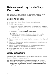
... telephone cables, network cables and so on, from your computer. 5 Disconnect all attached devices and peripherals, such as keyboard, mouse, monitor, and so on, from your computer. 6 Remove any media card and optical disc from your computer, if applicable. Windows 8: Move your mouse pointer to the upper-right or lowerright corner of your operating system for shut-down instructions. 3 Disconnect your computer and all open applications...
... telephone cables, network cables and so on, from your computer. 5 Disconnect all attached devices and peripherals, such as keyboard, mouse, monitor, and so on, from your computer. 6 Remove any media card and optical disc from your computer, if applicable. Windows 8: Move your mouse pointer to the upper-right or lowerright corner of your operating system for shut-down instructions. 3 Disconnect your computer and all open applications...

Owners Manual
Page 11
... a network cable, first unplug the cable from your computer and then unplug the cable from the media-card reader. WARNING: Disconnect all covers, panels, and screws before connecting to the power source. CAUTION: Only a certified service technician is flat and clean. CAUTION: Press and eject any connector pins. Some cables have connectors with locking tabs or thumb-screws that you work surface is authorized to remove...
... a network cable, first unplug the cable from your computer and then unplug the cable from the media-card reader. WARNING: Disconnect all covers, panels, and screws before connecting to the power source. CAUTION: Only a certified service technician is flat and clean. CAUTION: Press and eject any connector pins. Some cables have connectors with locking tabs or thumb-screws that you work surface is authorized to remove...

Owners Manual
Page 12
After Working Inside Your Computer CAUTION: Leaving stray or loose screws inside your computer may severely damage your computer. 1 Replace all screws and make sure that no stray screws remain inside your computer. 2 Connect any external devices, peripherals, and cables you removed before working on your computer. 3 Replace any media cards, discs, and any other part(s) that you removed before working on your computer. 4 Connect your computer and all attached devices to their electrical outlets. 5 Turn on your computer. 12
After Working Inside Your Computer CAUTION: Leaving stray or loose screws inside your computer may severely damage your computer. 1 Replace all screws and make sure that no stray screws remain inside your computer. 2 Connect any external devices, peripherals, and cables you removed before working on your computer. 3 Replace any media cards, discs, and any other part(s) that you removed before working on your computer. 4 Connect your computer and all attached devices to their electrical outlets. 5 Turn on your computer. 12

Owners Manual
Page 23
After working inside your computer and follow the instructions in Before Working Inside Your Computer. For more safety best practices, see the Regulatory Compliance home page at dell.com/regulatory_compliance. Removing the Memory Module WARNING: Before working inside your computer, read the safety information that shipped with your computer, follow the steps in After Working Inside Your Computer. Prerequisites 1 Remove the battery. 2 Remove the base cover. 23
After working inside your computer and follow the instructions in Before Working Inside Your Computer. For more safety best practices, see the Regulatory Compliance home page at dell.com/regulatory_compliance. Removing the Memory Module WARNING: Before working inside your computer, read the safety information that shipped with your computer, follow the steps in After Working Inside Your Computer. Prerequisites 1 Remove the battery. 2 Remove the base cover. 23

Owners Manual
Page 24
Procedure 1 Using your fingertips, pry apart the securing clips on each end of the memory-module slot until the memory module pops up. 2 Slide and remove the memory module from the memory-module slot. 1 memory module 3 memory-module slot 2 securing clips (2) 24
Procedure 1 Using your fingertips, pry apart the securing clips on each end of the memory-module slot until the memory module pops up. 2 Slide and remove the memory module from the memory-module slot. 1 memory module 3 memory-module slot 2 securing clips (2) 24

Owners Manual
Page 26
Procedure 1 Align the notch on the memory module with the tab on the memorymodule slot. 2 Slide the memory module into the slot at an angle and press the memory module down until it . 1 memory module 3 notch 5 memory-module slot Post-requisites 1 Replace the base cover. 2 Replace the battery. 2 securing clips (2) 4 tab 26 NOTE: If you do not hear the click, remove the memory module and reinstall it clicks into place.
Procedure 1 Align the notch on the memory module with the tab on the memorymodule slot. 2 Slide the memory module into the slot at an angle and press the memory module down until it . 1 memory module 3 notch 5 memory-module slot Post-requisites 1 Replace the base cover. 2 Replace the battery. 2 securing clips (2) 4 tab 26 NOTE: If you do not hear the click, remove the memory module and reinstall it clicks into place.

Owners Manual
Page 32
NOTE: If you are installing a new keyboard, make sure to note the folding of the keyboard cable and keyboard-backlight cable (optional). 1 keyboard-backlight cable (optional) 3 keyboard 2 connector latch 4 keyboard cable 32 5 Lift the keyboard along with the cables off the palm rest.
NOTE: If you are installing a new keyboard, make sure to note the folding of the keyboard cable and keyboard-backlight cable (optional). 1 keyboard-backlight cable (optional) 3 keyboard 2 connector latch 4 keyboard cable 32 5 Lift the keyboard along with the cables off the palm rest.

Owners Manual
Page 59
... at dell.com/regulatory_compliance. It is recommended that shipped with your computer, follow the steps in "Removing the Hard Drive". 4 Remove the keyboard. 5 Follow the procedure from step 1 to default. Procedure Using a plastic scribe, gently pry out the coin-cell battery out of the battery socket on the system board. 59 CAUTION: Removing the coin-cell battery resets the BIOS settings to step 7 in After Working Inside...
... at dell.com/regulatory_compliance. It is recommended that shipped with your computer, follow the steps in "Removing the Hard Drive". 4 Remove the keyboard. 5 Follow the procedure from step 1 to default. Procedure Using a plastic scribe, gently pry out the coin-cell battery out of the battery socket on the system board. 59 CAUTION: Removing the coin-cell battery resets the BIOS settings to step 7 in After Working Inside...

Owners Manual
Page 68
... board removes any changes you replace the system board. You must make the desired changes again after you replace the system board. Prerequisites 1 Remove the battery. 2 Remove the base cover. 3 Remove the memory module. 4 Follow the procedure from step 1 to step 3 in "Removing the Hard Drive". 5 Follow the procedure from step 1 to the system board. 2 Lift the connector latches and disconnect the display cable and I/O- After working inside your computer and follow the instructions...
... board removes any changes you replace the system board. You must make the desired changes again after you replace the system board. Prerequisites 1 Remove the battery. 2 Remove the base cover. 3 Remove the memory module. 4 Follow the procedure from step 1 to step 3 in "Removing the Hard Drive". 5 Follow the procedure from step 1 to the system board. 2 Lift the connector latches and disconnect the display cable and I/O- After working inside your computer and follow the instructions...
Owners Manual
Page 71
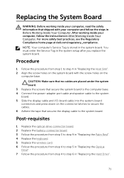
... your computer and follow the instructions in "Replacing the Hard Drive". 71 Replacing the System Board WARNING: Before working inside your computer, read the safety information that secures the display cable to the system board. Post-requisites 1 Replace the optical-drive connector board. 2 Replace the battery-connector board. 3 Follow the procedure from step 3 to step 9 in "Replacing the Palm Rest". 4 Replace the keyboard. 5 Replace the wireless card. 6 Follow the procedure from step...
... your computer and follow the instructions in "Replacing the Hard Drive". 71 Replacing the System Board WARNING: Before working inside your computer, read the safety information that secures the display cable to the system board. Post-requisites 1 Replace the optical-drive connector board. 2 Replace the battery-connector board. 3 Follow the procedure from step 3 to step 9 in "Replacing the Palm Rest". 4 Replace the keyboard. 5 Replace the wireless card. 6 Follow the procedure from step...

Owners Manual
Page 88
.... 3 Replace the power-adapter port. 4 Follow the procedure from step 3 to step 9 in "Replacing the Palm Rest". 5 Replace the keyboard. 6 Follow the procedure from step 4 to step 5 in "Replacing the Optical Drive". 7 Follow the procedure from step 4 to the display backcover. Replacing the Display Panel WARNING: Before working inside your computer, read the safety information that secure the display panel to step 6 in "Replacing the Hard Drive". 8 Replace the base cover. 9 Replace...
.... 3 Replace the power-adapter port. 4 Follow the procedure from step 3 to step 9 in "Replacing the Palm Rest". 5 Replace the keyboard. 6 Follow the procedure from step 4 to step 5 in "Replacing the Optical Drive". 7 Follow the procedure from step 4 to the display backcover. Replacing the Display Panel WARNING: Before working inside your computer, read the safety information that secure the display panel to step 6 in "Replacing the Hard Drive". 8 Replace the base cover. 9 Replace...

Owners Manual
Page 94
... computer and follow the instructions in "Replacing the Hard Drive". 8 Replace the base cover. 9 Replace the battery. 94 Post-requisites 1 Replace the display bezel. 2 Replace the display assembly. 3 Replace the power-adapter port. 4 Follow the procedure from step 3 to step 9 in "Replacing the Palm Rest". 5 Replace the keyboard. 6 Follow the procedure from step 4 to step 5 in "Replacing the Optical Drive". 7 Follow the procedure from step 4 to the display back-cover. For more safety...
... computer and follow the instructions in "Replacing the Hard Drive". 8 Replace the base cover. 9 Replace the battery. 94 Post-requisites 1 Replace the display bezel. 2 Replace the display assembly. 3 Replace the power-adapter port. 4 Follow the procedure from step 3 to step 9 in "Replacing the Palm Rest". 5 Replace the keyboard. 6 Follow the procedure from step 4 to step 5 in "Replacing the Optical Drive". 7 Follow the procedure from step 4 to the display back-cover. For more safety...

Owners Manual
Page 96
... so on Dell products and services using your country. 96 Click Start → Help and Support. Information about Dell products and See dell.com services Troubleshooting information, user manuals, setup instructions, product specifications, technical help blogs, drivers, software updates, and so on See dell.com/support Information about Microsoft Windows 8 See dell.com/windows8 Information about Microsoft Windows 7 Click Start → All Programs → Dell Help Documentation Learn about your operating system, setting up and using these...
... so on Dell products and services using your country. 96 Click Start → Help and Support. Information about Dell products and See dell.com services Troubleshooting information, user manuals, setup instructions, product specifications, technical help blogs, drivers, software updates, and so on See dell.com/support Information about Microsoft Windows 8 See dell.com/windows8 Information about Microsoft Windows 7 Click Start → All Programs → Dell Help Documentation Learn about your operating system, setting up and using these...

Specifications
Page 8
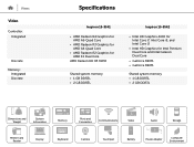
...-6210 • AMD A6-6310 Integrated in processor Inspiron 15-3542 • 4th Generation Intel Core i7 • 4th Generation Intel Core i5 • 4th Generation Intel Core i3 • Intel Pentium Dual Core • Intel Celeron Dual Core Integrated in processor Dimensions and Weight System Information Memory Ports and Connectors Communications Video Audio Storage Media-Card Reader Display Keyboard Camera Touchpad Battery Power Adapter Computer Environment
...-6210 • AMD A6-6310 Integrated in processor Inspiron 15-3542 • 4th Generation Intel Core i7 • 4th Generation Intel Core i5 • 4th Generation Intel Core i3 • Intel Pentium Dual Core • Intel Celeron Dual Core Integrated in processor Dimensions and Weight System Information Memory Ports and Connectors Communications Video Audio Storage Media-Card Reader Display Keyboard Camera Touchpad Battery Power Adapter Computer Environment
Specifications
Page 12
... Intel Core i3 • Intel HD Graphics for Intel Pentium Dual Core and Intel Celeron Dual Core • GeForce 820M • GeForce 840M Shared system memory • 1 GB DDR3L • 2 GB DDR3L Dimensions and Weight System Information Memory Ports and Connectors Communications Video Audio Storage Media-Card Reader Display Keyboard Camera Touchpad Battery Power Adapter Computer Environment
... Intel Core i3 • Intel HD Graphics for Intel Pentium Dual Core and Intel Celeron Dual Core • GeForce 820M • GeForce 840M Shared system memory • 1 GB DDR3L • 2 GB DDR3L Dimensions and Weight System Information Memory Ports and Connectors Communications Video Audio Storage Media-Card Reader Display Keyboard Camera Touchpad Battery Power Adapter Computer Environment
Specifications
Page 13
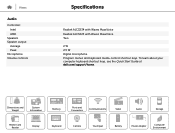
... learn about your computer keyboard shortcut keys, see the Quick Start Guide at dell.com/support/home. Dimensions and Weight System Information Memory Ports and Connectors Communications Video Audio Storage Media-Card Reader Display Keyboard Camera Touchpad Battery Power Adapter Computer Environment Views Audio Controller: Intel AMD Speakers Speaker output: Average Peak Microphone Volume controls Specifications Realtek ALC3234 with Waves MaxxVoice Realtek ALC3223 with Waves MaxxVoice Two 2 W 2.5 W Digital microphone Program menus and keyboard media-control shortcut keys.
... learn about your computer keyboard shortcut keys, see the Quick Start Guide at dell.com/support/home. Dimensions and Weight System Information Memory Ports and Connectors Communications Video Audio Storage Media-Card Reader Display Keyboard Camera Touchpad Battery Power Adapter Computer Environment Views Audio Controller: Intel AMD Speakers Speaker output: Average Peak Microphone Volume controls Specifications Realtek ALC3234 with Waves MaxxVoice Realtek ALC3223 with Waves MaxxVoice Two 2 W 2.5 W Digital microphone Program menus and keyboard media-control shortcut keys.
Specifications
Page 16
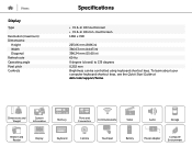
To learn about your computer keyboard shortcut keys, see the Quick Start Guide at dell.com/support/home. Dimensions and Weight System Information Memory Ports and Connectors Communications Video Audio Storage Media-Card Reader Display Keyboard Camera Touchpad Battery Power Adapter Computer Environment Views Display Type Resolution (maximum) Dimensions: Height Width Diagonal Refresh rate Operating angle Pixel pitch Controls Specifications • 15.6-in HD touchscreen • 15.6-in HD non-touchscreen 1366 x 768 225.06 mm (8.86 in) 366...
To learn about your computer keyboard shortcut keys, see the Quick Start Guide at dell.com/support/home. Dimensions and Weight System Information Memory Ports and Connectors Communications Video Audio Storage Media-Card Reader Display Keyboard Camera Touchpad Battery Power Adapter Computer Environment Views Display Type Resolution (maximum) Dimensions: Height Width Diagonal Refresh rate Operating angle Pixel pitch Controls Specifications • 15.6-in HD touchscreen • 15.6-in HD non-touchscreen 1366 x 768 225.06 mm (8.86 in) 366...
Specifications
Page 17
... secondary functions, press Fn and the desired key. Dimensions and Weight System Information Memory Ports and Connectors Communications Video Audio Storage Media-Card Reader Display Keyboard Camera Touchpad Battery Power Adapter Computer Environment Views Keyboard Type Shortcut keys Specifications • Standard keyboard • Backlit keyboard (optional) Some keys on your keyboard have two symbols on them. These keys can define the primary behavior of the shortcut keys by changing Function Key Behavior in BIOS setup program. NOTE: You can be used to type alternate...
... secondary functions, press Fn and the desired key. Dimensions and Weight System Information Memory Ports and Connectors Communications Video Audio Storage Media-Card Reader Display Keyboard Camera Touchpad Battery Power Adapter Computer Environment Views Keyboard Type Shortcut keys Specifications • Standard keyboard • Backlit keyboard (optional) Some keys on your keyboard have two symbols on them. These keys can define the primary behavior of the shortcut keys by changing Function Key Behavior in BIOS setup program. NOTE: You can be used to type alternate...


