Owners Manual
Page 3
Contents 1 Before You Begin 9 Recommended Tools 9 Turning Off Your Computer 9 Before Working Inside Your Computer 10 2 Battery 13 Removing the Battery 13 Replacing the Battery 14 3 Keyboard 15 Removing the Keyboard 15 Replacing the Keyboard 17 4 Memory Module(s 19 Removing the Memory Module(s 19 Replacing the Memory Module(s 20 5 Optical Drive 23 Removing the Optical Drive 23 Contents 3
Contents 1 Before You Begin 9 Recommended Tools 9 Turning Off Your Computer 9 Before Working Inside Your Computer 10 2 Battery 13 Removing the Battery 13 Replacing the Battery 14 3 Keyboard 15 Removing the Keyboard 15 Replacing the Keyboard 17 4 Memory Module(s 19 Removing the Memory Module(s 19 Replacing the Memory Module(s 20 5 Optical Drive 23 Removing the Optical Drive 23 Contents 3
Owners Manual
Page 5
11 Coin-Cell Battery 43 Removing the Coin-Cell Battery 43 Replacing the Coin-Cell Battery 45 12 USB Board 47 Removing the USB Board 47 Replacing the USB Board 48 13 Thermal Cooling Assembly 49 Removing the Thermal Cooling Assembly 49 Replacing the Thermal Cooling Assembly 50 14 Processor Module (For Inspiron 14-N4050 Only) 51 Removing the Processor Module 51 Replacing the Processor Module 52 15 Hinge Cover 55 Removing the Hinge Cover 55 Replacing the Hinge Cover 57 16 Display 59 Display Assembly 59 Contents 5
11 Coin-Cell Battery 43 Removing the Coin-Cell Battery 43 Replacing the Coin-Cell Battery 45 12 USB Board 47 Removing the USB Board 47 Replacing the USB Board 48 13 Thermal Cooling Assembly 49 Removing the Thermal Cooling Assembly 49 Replacing the Thermal Cooling Assembly 50 14 Processor Module (For Inspiron 14-N4050 Only) 51 Removing the Processor Module 51 Replacing the Processor Module 52 15 Hinge Cover 55 Removing the Hinge Cover 55 Replacing the Hinge Cover 57 16 Display 59 Display Assembly 59 Contents 5
Owners Manual
Page 10
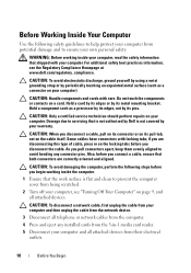
... Working Inside Your Computer Use the following steps before you connect a cable, ensure that shipped with your own personal safety. For additional safety best practices information, see "Turning Off Your Computer" on page 9, and all telephone or network cables from the computer. 4 Press and eject any connector pins. Damage due to servicing that the work surface is not covered by Dell...
... Working Inside Your Computer Use the following steps before you connect a cable, ensure that shipped with your own personal safety. For additional safety best practices information, see "Turning Off Your Computer" on page 9, and all telephone or network cables from the computer. 4 Press and eject any connector pins. Damage due to servicing that the work surface is not covered by Dell...

Owners Manual
Page 19
... board, remove the main battery, see the Regulatory Compliance Homepage at support.dell.com/manuals. Memory 19 NOTE: Memory modules purchased from the bottom of memory supported by periodically touching an unpainted metal surface (such as a connector on the type of the computer. You can be accessed from Dell are covered under your computer. For additional safety best practices information, see "Removing the Battery" on page 13. 3 Remove the keyboard. 4 Memory Module...
... board, remove the main battery, see the Regulatory Compliance Homepage at support.dell.com/manuals. Memory 19 NOTE: Memory modules purchased from the bottom of memory supported by periodically touching an unpainted metal surface (such as a connector on the type of the computer. You can be accessed from Dell are covered under your computer. For additional safety best practices information, see "Removing the Battery" on page 13. 3 Remove the keyboard. 4 Memory Module...
Owners Manual
Page 20
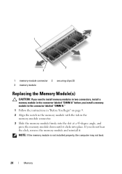
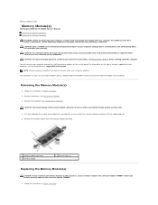
... instructions in "Before You Begin" on page 9. 2 Align the notch in the memory module with the tab in the connector labeled "DIMM A" before you do not hear the click, remove the memory module and reinstall it clicks into the slot at a 45-degree angle, and press the memory module down until it . 1 3 2 1 memory-module connector 2 securing clips (2) 3 memory module Replacing the Memory Module(s) CAUTION: If you need...
... instructions in "Before You Begin" on page 9. 2 Align the notch in the memory module with the tab in the connector labeled "DIMM A" before you do not hear the click, remove the memory module and reinstall it clicks into the slot at a 45-degree angle, and press the memory module down until it . 1 3 2 1 memory-module connector 2 securing clips (2) 3 memory module Replacing the Memory Module(s) CAUTION: If you need...
Owners Manual
Page 35
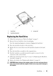
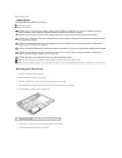
See "Replacing the Battery" on the computer, replace all screws and ensure that secure the hard-drive bracket to the hard drive. 5 Place the hard-drive assembly on the computer base. 6 Push the hard-drive assembly towards the right to connect it to the connector on the system board. 7 Follow the instructions from step 3 to the computer. CAUTION: Before turning on page 14. Save the original packaging...
See "Replacing the Battery" on the computer, replace all screws and ensure that secure the hard-drive bracket to the hard drive. 5 Place the hard-drive assembly on the computer base. 6 Push the hard-drive assembly towards the right to connect it to the connector on the system board. 7 Follow the instructions from step 3 to the computer. CAUTION: Before turning on page 14. Save the original packaging...
Owners Manual
Page 39
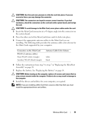
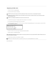
... for your computer. CAUTION: Before turning on the system-board. 4 Press the other than Dell, you are installing a Mini-Card from step 3 to the Mini-Card, never place cables under the card. 3 Insert the Mini-Card connector at a 45-degree angle into place. 5 Connect the appropriate antenna cables to the computer. 8 Install the drivers and utilities for the Mini-Cards supported by your computer, as required...
... for your computer. CAUTION: Before turning on the system-board. 4 Press the other than Dell, you are installing a Mini-Card from step 3 to the Mini-Card, never place cables under the card. 3 Insert the Mini-Card connector at a 45-degree angle into place. 5 Connect the appropriate antenna cables to the computer. 8 Install the drivers and utilities for the Mini-Cards supported by your computer, as required...
Owners Manual
Page 45
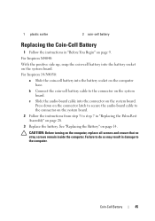
... system board. See "Replacing the Battery" on the computer base. For Inspiron 14-N4050: a Slide the coin-cell battery into the connector on page 9. Press down on the connector latch to secure the audio-board cable to the connector on the system board. 2 Follow the instructions from step 3 to the connector on page 28. 3 Replace the battery. Coin-Cell Battery 45 b Connect the coin-cell battery cable to...
... system board. See "Replacing the Battery" on the computer base. For Inspiron 14-N4050: a Slide the coin-cell battery into the connector on page 9. Press down on the connector latch to secure the audio-board cable to the connector on the system board. 2 Follow the instructions from step 3 to the connector on page 28. 3 Replace the battery. Coin-Cell Battery 45 b Connect the coin-cell battery cable to...
Owners Manual
Page 51
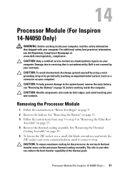
... socket, use a small, flat-blade screwdriver and rotate the ZIF-socket cam screw counterclockwise until it comes to the system board, remove the main battery, see the Regulatory Compliance Homepage at www.dell.com/regulatory_compliance. 14 Processor Module (For Inspiron 14-N4050 Only) WARNING: Before working inside your computer, read the safety information that is not authorized by Dell is not covered by...
... socket, use a small, flat-blade screwdriver and rotate the ZIF-socket cam screw counterclockwise until it comes to the system board, remove the main battery, see the Regulatory Compliance Homepage at www.dell.com/regulatory_compliance. 14 Processor Module (For Inspiron 14-N4050 Only) WARNING: Before working inside your computer, read the safety information that is not authorized by Dell is not covered by...
Owners Manual
Page 52
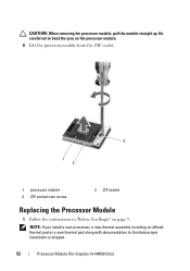
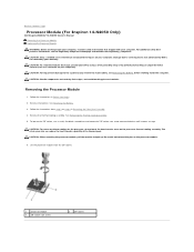
NOTE: If you install a new processor, a new thermal assembly including an affixed thermal pad or a new thermal pad along with documentation to bend the pins on the processor module. 6 Lift the processor module from the ZIF socket. 3 1 2 1 processor module 3 ZIF-socket cam screw 2 ZIF socket Replacing the Processor Module 1 Follow the instructions in "Before You Begin" on page 9. Be careful not to illustrate proper installation is shipped. 52 Processor Module (For Inspiron 14-N4050 Only) CAUTION: When removing the processor module, pull the module straight up.
NOTE: If you install a new processor, a new thermal assembly including an affixed thermal pad or a new thermal pad along with documentation to bend the pins on the processor module. 6 Lift the processor module from the ZIF socket. 3 1 2 1 processor module 3 ZIF-socket cam screw 2 ZIF socket Replacing the Processor Module 1 Follow the instructions in "Before You Begin" on page 9. Be careful not to illustrate proper installation is shipped. 52 Processor Module (For Inspiron 14-N4050 Only) CAUTION: When removing the processor module, pull the module straight up.
Owners Manual
Page 53
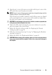
... Assembly" on page 28. 6 Replace the battery. 2 Align the pin-1 corner of the processor module with the triangle on the pin-1 corner of the ZIF socket. Processor Module (For Inspiron 14-N4050 Only) 53 See "Replacing the Thermal Cooling Assembly" on page 50. 5 Follow the instructions from step 3 to step 7 in damage to the system board. 4 Replace the thermal cooling assembly...
... Assembly" on page 28. 6 Replace the battery. 2 Align the pin-1 corner of the processor module with the triangle on the pin-1 corner of the ZIF socket. Processor Module (For Inspiron 14-N4050 Only) 53 See "Replacing the Thermal Cooling Assembly" on page 50. 5 Follow the instructions from step 3 to step 7 in damage to the system board. 4 Replace the thermal cooling assembly...
Owners Manual
Page 57
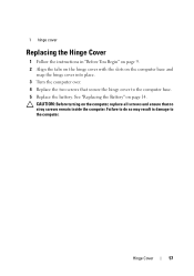
Failure to do so may result in "Before You Begin" on page 9. 2 Align the tabs on the hinge cover with the slots on the computer base and snap the hinge cover into place. 3 Turn the computer over. 4 Replace the two screws that no stray screws remain inside the computer. CAUTION: Before turning on page 14. Hinge Cover 57 1 hinge cover Replacing the Hinge Cover 1 Follow the instructions in damage to the computer base. 5 Replace the battery. See "Replacing the Battery" on the computer, replace all screws and ensure that secure the hinge cover to the computer.
Failure to do so may result in "Before You Begin" on page 9. 2 Align the tabs on the hinge cover with the slots on the computer base and snap the hinge cover into place. 3 Turn the computer over. 4 Replace the two screws that no stray screws remain inside the computer. CAUTION: Before turning on page 14. Hinge Cover 57 1 hinge cover Replacing the Hinge Cover 1 Follow the instructions in damage to the computer base. 5 Replace the battery. See "Replacing the Battery" on the computer, replace all screws and ensure that secure the hinge cover to the computer.
Owners Manual
Page 76
... main battery is installed properly. 2 Turn on page 28. 10 Replace the optical drive. Entering the Service Tag in the BIOS 1 Ensure that the AC adapter is plugged in -1 media card reader. See "Replacing the Battery" on page 76. See "Entering the Service Tag in the BIOS" on page 14. 14 Replace any removed cards or blanks in the 3-in and that no stray screws remain inside the computer. See "Replacing the Keyboard" on...
... main battery is installed properly. 2 Turn on page 28. 10 Replace the optical drive. Entering the Service Tag in the BIOS 1 Ensure that the AC adapter is plugged in -1 media card reader. See "Replacing the Battery" on page 76. See "Entering the Service Tag in the BIOS" on page 14. 14 Replace any removed cards or blanks in the 3-in and that no stray screws remain inside the computer. See "Replacing the Keyboard" on...
User Manual
Page 1
...;, and the Windows start button logo are not followed. is a registered trademark owned by Bluetooth SIG, Inc.; Dell Inspiron M4040/14-N4050 Owner's Manual Before You Begin Battery Keyboard Memory Module(s) Optical Drive Palm-Rest Assembly Power Button Board Hard Drive Wireless Mini-Card Audio Board Coin-Cell Battery USB Board Thermal Cooling Assembly Processor Module (For Inspiron 14-N4050 Only) Hinge Cover Display Camera Module System Board Flashing the BIOS Notes, Cautions, and Warnings NOTE: A NOTE indicates important information that helps you make better use of Dell Inc. WARNING...
...;, and the Windows start button logo are not followed. is a registered trademark owned by Bluetooth SIG, Inc.; Dell Inspiron M4040/14-N4050 Owner's Manual Before You Begin Battery Keyboard Memory Module(s) Optical Drive Palm-Rest Assembly Power Button Board Hard Drive Wireless Mini-Card Audio Board Coin-Cell Battery USB Board Thermal Cooling Assembly Processor Module (For Inspiron 14-N4050 Only) Hinge Cover Display Camera Module System Board Flashing the BIOS Notes, Cautions, and Warnings NOTE: A NOTE indicates important information that helps you make better use of Dell Inc. WARNING...
User Manual
Page 5
... Dell Inspiron M4040/14-N4050 Owner's Manual Recommended Tools Turning Off Your Computer Before Working Inside Your Computer This manual provides procedures for removing and installing components in this type of cable, press in on the locking tabs before you disconnect the cable. The computer turns off . if you begin any connector pins. As you shut down the operating system, press and hold the power button until the computer turns...
... Dell Inspiron M4040/14-N4050 Owner's Manual Recommended Tools Turning Off Your Computer Before Working Inside Your Computer This manual provides procedures for removing and installing components in this type of cable, press in on the locking tabs before you disconnect the cable. The computer turns off . if you begin any connector pins. As you shut down the operating system, press and hold the power button until the computer turns...
User Manual
Page 8
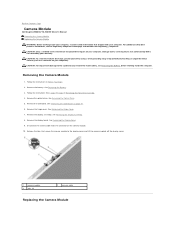
... due to servicing that is not authorized by Dell is not covered by periodically touching an unpainted metal surface (such as a connector on the camera module. 10. Follow the instructions in Removing the Palm-Rest Assembly. 4. Remove the battery. Remove the hinge cover. See Removing the Hinge Cover. 7. Remove the display assembly. Remove the USB board. See Removing the Display Bezel. 9. Back to Contents Page Camera Module Dell Inspiron M4040/14-N4050 Owner's Manual Removing the Camera Module Replacing the Camera Module WARNING: Before working inside...
... due to servicing that is not authorized by Dell is not covered by periodically touching an unpainted metal surface (such as a connector on the camera module. 10. Follow the instructions in Removing the Palm-Rest Assembly. 4. Remove the battery. Remove the hinge cover. See Removing the Hinge Cover. 7. Remove the display assembly. Remove the USB board. See Removing the Display Bezel. 9. Back to Contents Page Camera Module Dell Inspiron M4040/14-N4050 Owner's Manual Removing the Camera Module Replacing the Camera Module WARNING: Before working inside...
User Manual
Page 17
... Hard Drive Dell Inspiron M4040/14-N4050 Owner's Manual Removing the Hard Drive Replacing the Hard Drive WARNING: Before working inside your computer, read the safety information that shipped with your warranty. CAUTION: To avoid electrostatic discharge, ground yourself by using a wrist grounding strap or by Dell is hot, do not touch the metal housing of the computer base. 1 hard-drive assembly 6. Follow the instructions in Before You Begin. 2. Damage due to servicing...
... Hard Drive Dell Inspiron M4040/14-N4050 Owner's Manual Removing the Hard Drive Replacing the Hard Drive WARNING: Before working inside your computer, read the safety information that shipped with your warranty. CAUTION: To avoid electrostatic discharge, ground yourself by using a wrist grounding strap or by Dell is hot, do not touch the metal housing of the computer base. 1 hard-drive assembly 6. Follow the instructions in Before You Begin. 2. Damage due to servicing...
User Manual
Page 25
... a certified service technician should perform repairs on your fingertips to carefully spread apart the securing clips on each end of memory supported by periodically touching an unpainted metal surface (such as a connector on the type of the memory-module connector until the module pops up. 5. For information on your computer). Back to Contents Page Memory Module(s) Dell Inspiron M4040/14-N4050 Owner's Manual Removing the Memory Module(s) Replacing the Memory Module(s) WARNING: Before working inside...
... a certified service technician should perform repairs on your fingertips to carefully spread apart the securing clips on each end of memory supported by periodically touching an unpainted metal surface (such as a connector on the type of the memory-module connector until the module pops up. 5. For information on your computer). Back to Contents Page Memory Module(s) Dell Inspiron M4040/14-N4050 Owner's Manual Removing the Memory Module(s) Replacing the Memory Module(s) WARNING: Before working inside...
User Manual
Page 28
... Mini-Card Antenna Cable Color Scheme WLAN (2 antenna cables) Main WLAN (white triangle) white Auxiliary WLAN (black triangle) black 6. See Replacing the Battery. Failure to the computer. 8. Install the drivers and utilities for the Mini- Remove the new Mini-Card from a source other end of the Mini-Card down until it clicks into the connector on the system board, and realign the card. Replace the battery. Follow the instructions...
... Mini-Card Antenna Cable Color Scheme WLAN (2 antenna cables) Main WLAN (white triangle) white Auxiliary WLAN (black triangle) black 6. See Replacing the Battery. Failure to the computer. 8. Install the drivers and utilities for the Mini- Remove the new Mini-Card from a source other end of the Mini-Card down until it clicks into the connector on the system board, and realign the card. Replace the battery. Follow the instructions...
User Manual
Page 34
... comes to the system board, remove the main battery, see the Regulatory Compliance Homepage at www.dell.com/regulatory_compliance. CAUTION: To ensure maximum cooling for the processor, do not touch the heat transfer areas on the processor module. 6. Back to Contents Page Processor Module (For Inspiron 14-N4050 Only) Dell Inspiron M4040/14-N4050 Owner's Manual Removing the Processor Module Replacing the Processor Module WARNING: Before working inside your computer, read...
... comes to the system board, remove the main battery, see the Regulatory Compliance Homepage at www.dell.com/regulatory_compliance. CAUTION: To ensure maximum cooling for the processor, do not touch the heat transfer areas on the processor module. 6. Back to Contents Page Processor Module (For Inspiron 14-N4050 Only) Dell Inspiron M4040/14-N4050 Owner's Manual Removing the Processor Module Replacing the Processor Module WARNING: Before working inside your computer, read...


