
Owners Manual
Page 33
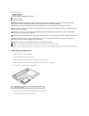
... 25. WARNING: If you must install an operating system, drivers, and utilities on page 13. 3 Follow the instructions from sources other than Dell. Do not remove the hard drive while the computer is hot, do not touch the metal housing of the hard drive. NOTE: If you... your computer, read the safety information that is not authorized by Dell is not covered by periodically touching an unpainted metal surface (such as a connector on page 9. 2 Remove the battery. See "Removing the Battery" on the new hard drive. For additional safety best practices information, see "Removing the...
... 25. WARNING: If you must install an operating system, drivers, and utilities on page 13. 3 Follow the instructions from sources other than Dell. Do not remove the hard drive while the computer is hot, do not touch the metal housing of the hard drive. NOTE: If you... your computer, read the safety information that is not authorized by Dell is not covered by periodically touching an unpainted metal surface (such as a connector on page 9. 2 Remove the battery. See "Removing the Battery" on the new hard drive. For additional safety best practices information, see "Removing the...
Owners Manual
Page 35
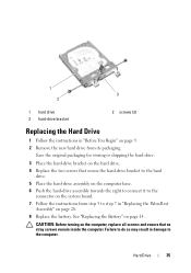
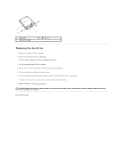
Hard Drive 35 See "Replacing the Battery" on page 9. 2 Remove the new hard drive from step 3 to step 7 in "Replacing the Palm-Rest Assembly" on the computer, replace all screws and ensure that secure the hard-drive ... to connect it to the computer. 1 3 2 1 hard drive 3 hard-drive bracket 2 screws (2) Replacing the Hard Drive 1 Follow the instructions in "Before You Begin" on page 14. Failure to do so may result in damage to the connector on the system board. 7 Follow the instructions from its packaging. CAUTION: Before turning on...
Hard Drive 35 See "Replacing the Battery" on page 9. 2 Remove the new hard drive from step 3 to step 7 in "Replacing the Palm-Rest Assembly" on the computer, replace all screws and ensure that secure the hard-drive ... to connect it to the computer. 1 3 2 1 hard drive 3 hard-drive bracket 2 screws (2) Replacing the Hard Drive 1 Follow the instructions in "Before You Begin" on page 14. Failure to do so may result in damage to the connector on the system board. 7 Follow the instructions from its packaging. CAUTION: Before turning on...
Owners Manual
Page 38
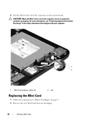
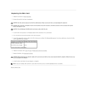
For more information, see "Protecting Against Electrostatic Discharge" in the safety information that shipped with your computer. 1 2 1 Mini-Card antenna cables (2) 2 tab Replacing the Mini-Card 1 Follow the instructions in protective antistatic packaging. 6 Lift the Mini-Card out of the connector on page 9. 2 Remove the new Mini-Card from its packaging. 38 Wireless Mini-Card CAUTION: When the Mini-Card is not in the computer, store it in "Before You Begin" on the system board.
For more information, see "Protecting Against Electrostatic Discharge" in the safety information that shipped with your computer. 1 2 1 Mini-Card antenna cables (2) 2 tab Replacing the Mini-Card 1 Follow the instructions in protective antistatic packaging. 6 Lift the Mini-Card out of the connector on page 9. 2 Remove the new Mini-Card from its packaging. 38 Wireless Mini-Card CAUTION: When the Mini-Card is not in the computer, store it in "Before You Begin" on the system board.
Owners Manual
Page 52
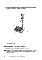
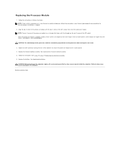
CAUTION: When removing the processor module, pull the module straight up. NOTE: If you install a new processor, a new thermal assembly including an affixed thermal pad or a new thermal pad along with documentation to bend the pins on the processor module. 6 Lift the processor module from the ZIF socket. 3 1 2 1 processor module 3 ZIF-socket cam screw 2 ZIF socket Replacing the Processor Module 1 Follow the instructions in "Before You Begin" on page 9. Be careful not to illustrate proper installation is shipped. 52 Processor Module (For Inspiron 14-N4050 Only)
CAUTION: When removing the processor module, pull the module straight up. NOTE: If you install a new processor, a new thermal assembly including an affixed thermal pad or a new thermal pad along with documentation to bend the pins on the processor module. 6 Lift the processor module from the ZIF socket. 3 1 2 1 processor module 3 ZIF-socket cam screw 2 ZIF socket Replacing the Processor Module 1 Follow the instructions in "Before You Begin" on page 9. Be careful not to illustrate proper installation is shipped. 52 Processor Module (For Inspiron 14-N4050 Only)
User Manual
Page 17
... the instructions in Sleep state. See Removing the Battery. 3. Back to Contents Page Hard Drive Dell Inspiron M4040/14-N4050 Owner's Manual Removing the Hard Drive Replacing the Hard Drive WARNING: Before working inside your computer, read the safety information that ...1 hard-drive assembly 6. Lift the hard-drive assembly out of the hard drive. CAUTION: Only a certified service technician should perform repairs on the new hard drive. Removing the Hard Drive 1. NOTE: If you are extremely fragile. WARNING: If you must install an operating system, drivers, and utilities ...
... the instructions in Sleep state. See Removing the Battery. 3. Back to Contents Page Hard Drive Dell Inspiron M4040/14-N4050 Owner's Manual Removing the Hard Drive Replacing the Hard Drive WARNING: Before working inside your computer, read the safety information that ...1 hard-drive assembly 6. Lift the hard-drive assembly out of the hard drive. CAUTION: Only a certified service technician should perform repairs on the new hard drive. Removing the Hard Drive 1. NOTE: If you are extremely fragile. WARNING: If you must install an operating system, drivers, and utilities ...
User Manual
Page 18
...-drive bracket on the computer base. 6. Follow the instructions from its packaging. See Replacing the Battery. CAUTION: Before turning on the system board. 7. Remove the new hard drive from step 3 to the connector on the computer, replace all screws and ensure that secure the hard-drive bracket to the hard drive...
...-drive bracket on the computer base. 6. Follow the instructions from its packaging. See Replacing the Battery. CAUTION: Before turning on the system board. 7. Remove the new hard drive from step 3 to the connector on the computer, replace all screws and ensure that secure the hard-drive bracket to the hard drive...
User Manual
Page 28
Press the other than Dell, you must install the appropriate drivers and utilities. NOTE: If you feel resistance, check the connectors on the card and on the system-board. 4. CAUTION: ... its packaging. Connectors on the computer, replace all screws and ensure that no stray screws remain inside the computer. See Replacing the Battery. Remove the new Mini-Card from a source other end of the Mini-Card down until it clicks into place. 5. The following table provides the antenna cable color scheme...
Press the other than Dell, you must install the appropriate drivers and utilities. NOTE: If you feel resistance, check the connectors on the card and on the system-board. 4. CAUTION: ... its packaging. Connectors on the computer, replace all screws and ensure that no stray screws remain inside the computer. See Replacing the Battery. Remove the new Mini-Card from a source other end of the Mini-Card down until it clicks into place. 5. The following table provides the antenna cable color scheme...
User Manual
Page 35
... screw. 3. See Replacing the Thermal Cooling Assembly. 5. Replace the thermal cooling assembly. Back to the computer. NOTE: If you install a new processor, a new thermal assembly including an affixed thermal pad or a new thermal pad along with documentation to do so may result in Replacing the Palm-Rest Assembly. 6. Failure to illustrate proper installation...
... screw. 3. See Replacing the Thermal Cooling Assembly. 5. Replace the thermal cooling assembly. Back to the computer. NOTE: If you install a new processor, a new thermal assembly including an affixed thermal pad or a new thermal pad along with documentation to do so may result in Replacing the Palm-Rest Assembly. 6. Failure to illustrate proper installation...

