
User Guide
Page 9
... Sequence 252 Option Settings 252 Changing Boot Sequence for the Current Boot 252 Changing Boot Sequence for Future Boots 253 Booting to a USB Device 253 Memory Key 253 Floppy Drive 253 Clearing Forgotten Passwords 254 Clearing CMOS Settings 256 Hyper-Threading 257 Power Management 257 9 Battery Replacing the Battery 259 Contents...
... Sequence 252 Option Settings 252 Changing Boot Sequence for the Current Boot 252 Changing Boot Sequence for Future Boots 253 Booting to a USB Device 253 Memory Key 253 Floppy Drive 253 Clearing Forgotten Passwords 254 Clearing CMOS Settings 256 Hyper-Threading 257 Power Management 257 9 Battery Replacing the Battery 259 Contents...
User Guide
Page 10
...System Board: Mini Tower, Desktop, and Small Form Factor Computers 266 11 Memory DDR2 Memory Overview 267 Addressing Memory With 4-GB Configurations 268 Removing Memory 269 Replacing/Adding Additional Memory 270 12 Replacing the ...Computer Cover 13 Cleaning Your Computer Computer, Keyboard, and Monitor 275 Mouse 275 Floppy Drive 275 CDs and DVDs 276 14 Reinstalling Drivers and the Operating System Drivers 277 What Is a Driver 277 Identifying Drivers 277 Reinstalling Drivers and Utilities 278 Using Windows XP...
...System Board: Mini Tower, Desktop, and Small Form Factor Computers 266 11 Memory DDR2 Memory Overview 267 Addressing Memory With 4-GB Configurations 268 Removing Memory 269 Replacing/Adding Additional Memory 270 12 Replacing the ...Computer Cover 13 Cleaning Your Computer Computer, Keyboard, and Monitor 275 Mouse 275 Floppy Drive 275 CDs and DVDs 276 14 Reinstalling Drivers and the Operating System Drivers 277 What Is a Driver 277 Identifying Drivers 277 Reinstalling Drivers and Utilities 278 Using Windows XP...

User Guide
Page 11
... 279 Undoing the Last System Restore 280 Enabling System Restore 280 Reinstalling Microsoft Windows XP 280 Before You Begin 280 Reinstalling Windows XP 281 Booting From the Operating System CD 281 Windows XP Setup 281 15 Solving Problems Battery Problems 285 Drive Problems 285 CD and ...responding 287 A program stops responding 288 A program crashes repeatedly 288 A solid blue screen appears 288 Other software problems 289 Memory Problems 289 Mouse Problems 290 Network Problems 291 Power Problems 291 Printer Problems 292 Restoring Default Settings 293 Serial or Parallel ...
... 279 Undoing the Last System Restore 280 Enabling System Restore 280 Reinstalling Microsoft Windows XP 280 Before You Begin 280 Reinstalling Windows XP 281 Booting From the Operating System CD 281 Windows XP Setup 281 15 Solving Problems Battery Problems 285 Drive Problems 285 CD and ...responding 287 A program stops responding 288 A program crashes repeatedly 288 A solid blue screen appears 288 Other software problems 289 Memory Problems 289 Mouse Problems 290 Network Problems 291 Power Problems 291 Printer Problems 292 Restoring Default Settings 293 Serial or Parallel ...

User Guide
Page 17
...Dell Support Website - Certified drivers, patches, and software updates • Desktop System Software (DSS) - The software automatically detects your computer and operating system and installs the updates appropriate for your region to use the customized Dell Premier Support website at premier.support.dell..., and repair information NOTE: Corporate, government, and education customers can also use Windows XP • Documentation for my computer • Documentation for devices (such as memory, the hard drive, and the operating system • Customer Care - Computer documentation...
...Dell Support Website - Certified drivers, patches, and software updates • Desktop System Software (DSS) - The software automatically detects your computer and operating system and installs the updates appropriate for your region to use the customized Dell Premier Support website at premier.support.dell..., and repair information NOTE: Corporate, government, and education customers can also use Windows XP • Documentation for my computer • Documentation for devices (such as memory, the hard drive, and the operating system • Customer Care - Computer documentation...

User Guide
Page 33
... Computer 33 1 fan connector (FAN) 12 password jumper (PSWD) 2 processor connector (CPU) 13 battery socket (BATT) 3 power connector (12VPOWER) 14 PCI Express x16 connector (SLOT1) 4 memory module connectors (DIMM_1, DIMM_2, 15 PCI Express x1 connector (SLOT4) DIMM_3, DIMM_4) 5 serial ATA drive connectors (SATA0, SATA2, SATA1, SATA3) 16 PCI connector (SLOT2) 6 front...
... Computer 33 1 fan connector (FAN) 12 password jumper (PSWD) 2 processor connector (CPU) 13 battery socket (BATT) 3 power connector (12VPOWER) 14 PCI Express x16 connector (SLOT1) 4 memory module connectors (DIMM_1, DIMM_2, 15 PCI Express x1 connector (SLOT4) DIMM_3, DIMM_4) 5 serial ATA drive connectors (SATA0, SATA2, SATA1, SATA3) 16 PCI connector (SLOT2) 6 front...
User Guide
Page 35
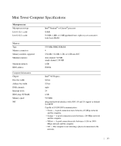
... a physical connection to the network. 35 Mini Tower Computer Specifications Microprocessor Microprocessor type Level 1 (L1) cache Level 2 (L2) cache Memory Type Memory connectors Memory modules supported Minimum memory Maximum memory BIOS address Computer Information Chipset Data bus width Address bus width DMA channels Interrupt levels BIOS chip (NVRAM...) Memory speed NIC Intel® Pentium® or Celeron® processor 32 KB 512-KB, 1-MB, or 2-MB pipelined-burst...
... a physical connection to the network. 35 Mini Tower Computer Specifications Microprocessor Microprocessor type Level 1 (L1) cache Level 2 (L2) cache Memory Type Memory connectors Memory modules supported Minimum memory Maximum memory BIOS address Computer Information Chipset Data bus width Address bus width DMA channels Interrupt levels BIOS chip (NVRAM...) Memory speed NIC Intel® Pentium® or Celeron® processor 32 KB 512-KB, 1-MB, or 2-MB pipelined-burst...

User Guide
Page 103
1 fan connector (FAN) 12 password jumper (PSWD) 2 processor connector (CPU) 13 battery socket (BATT) 3 power connector (12VPOWER) 14 PCI Express x16 connector (SLOT1) 4 memory module connectors (DIMM_1, DIMM_2, 15 PCI connector (SLOT3) DIMM_3, DIMM_4) 5 serial ATA drive connectors (SATA0, SATA2) 16 PCI riser connector (SLOT2) 6 front-panel connector (FNT_PANEL) ... board speaker (BEEP) 10 RTC reset jumper (RTCRST) 21 internal speaker (INT_SPKR) 11 intrusion switch connector (INTRUDER) Jumper Settings The jumper locations are shown below. Desktop Computer Desktop Computer 103
1 fan connector (FAN) 12 password jumper (PSWD) 2 processor connector (CPU) 13 battery socket (BATT) 3 power connector (12VPOWER) 14 PCI Express x16 connector (SLOT1) 4 memory module connectors (DIMM_1, DIMM_2, 15 PCI connector (SLOT3) DIMM_3, DIMM_4) 5 serial ATA drive connectors (SATA0, SATA2) 16 PCI riser connector (SLOT2) 6 front-panel connector (FNT_PANEL) ... board speaker (BEEP) 10 RTC reset jumper (RTCRST) 21 internal speaker (INT_SPKR) 11 intrusion switch connector (INTRUDER) Jumper Settings The jumper locations are shown below. Desktop Computer Desktop Computer 103

User Guide
Page 105
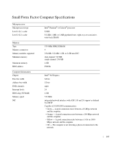
... the computer. • Off - A good connection exists between a 10-Mbps network and the computer. • Orange - Desktop Computer Specifications Microprocessor Microprocessor type Level 1 (L1) cache Level 2 (L2) cache Memory Type Memory connectors Memory modules supported Minimum memory Maximum memory BIOS address Computer Information Chipset Data bus width Address bus width DMA channels Interrupt levels BIOS chip...
... the computer. • Off - A good connection exists between a 10-Mbps network and the computer. • Orange - Desktop Computer Specifications Microprocessor Microprocessor type Level 1 (L1) cache Level 2 (L2) cache Memory Type Memory connectors Memory modules supported Minimum memory Maximum memory BIOS address Computer Information Chipset Data bus width Address bus width DMA channels Interrupt levels BIOS chip...

User Guide
Page 163
... Factor Computer 163 1 fan connector (FAN) 10 intrusion switch connector (INTRUDER) 2 processor connector (CPU) 11 password jumper (PSWD) 3 power connector (12VPOWER) 12 battery socket (BATT) 4 memory module connectors (DIMM_1, DIMM_2, 13 PCI Express x16 connector (SLOT1) DIMM_3, DIMM_4) 5 serial ATA drive connector (SATA0,) 14 PCI connector (SLOT2) 6 front-panel connector (FNT_PANEL...
... Factor Computer 163 1 fan connector (FAN) 10 intrusion switch connector (INTRUDER) 2 processor connector (CPU) 11 password jumper (PSWD) 3 power connector (12VPOWER) 12 battery socket (BATT) 4 memory module connectors (DIMM_1, DIMM_2, 13 PCI Express x16 connector (SLOT1) DIMM_3, DIMM_4) 5 serial ATA drive connector (SATA0,) 14 PCI connector (SLOT2) 6 front-panel connector (FNT_PANEL...
User Guide
Page 165
...) network and the computer. • Off - Small Form Factor Computer Specifications Microprocessor Microprocessor type Level 1 (L1) cache Level 2 (L2) cache Memory Type Memory connectors Memory modules supported Minimum memory Maximum memory BIOS address Computer Information Chipset Data bus width Address bus width DMA channels Interrupt levels BIOS chip (NVRAM...) Memory speed NIC Intel® Pentium® or Celeron® processor 32 KB 512-KB, 1-MB, or 2-MB pipelined-...
...) network and the computer. • Off - Small Form Factor Computer Specifications Microprocessor Microprocessor type Level 1 (L1) cache Level 2 (L2) cache Memory Type Memory connectors Memory modules supported Minimum memory Maximum memory BIOS address Computer Information Chipset Data bus width Address bus width DMA channels Interrupt levels BIOS chip (NVRAM...) Memory speed NIC Intel® Pentium® or Celeron® processor 32 KB 512-KB, 1-MB, or 2-MB pipelined-...
User Guide
Page 202
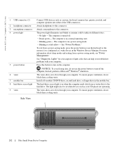
...The light might also be on when devices such as a mouse, keyboard, memory key, printer, joystick, and computer speakers into either of light codes that can help you troubleshoot problems with your computer. www.dell.com | support.dell.com 1 USB connectors (2) 2 headphone connector 3 microphone connector 4 power light... Lights" for a description of the USB connectors. Install a D-module CD/DVD drive, second hard drive, or floppy drive in the Windows Device Manager. The vents allow air to indicate different states: • No light - To exit from a power-saving mode, press ...
...The light might also be on when devices such as a mouse, keyboard, memory key, printer, joystick, and computer speakers into either of light codes that can help you troubleshoot problems with your computer. www.dell.com | support.dell.com 1 USB connectors (2) 2 headphone connector 3 microphone connector 4 power light... Lights" for a description of the USB connectors. Install a D-module CD/DVD drive, second hard drive, or floppy drive in the Windows Device Manager. The vents allow air to indicate different states: • No light - To exit from a power-saving mode, press ...

User Guide
Page 206
You can do so by touching an unpainted metal surface on the computer chassis. 1 2 3 6 5 1 heat sink assembly 2 speaker (optional) 3 memory modules (2) 4 4 hard drive 5 security cable slot 6 chassis intrusion switch 206 Ultra Small Form Factor Computer www.dell.com | support.dell.com CAUTION: To avoid electrical shock, always unplug your computer's electronic components. NOTICE: To prevent static damage to components inside your computer, discharge static electricity from your body before you touch any of your computer from the power adapter before removing the cover.
You can do so by touching an unpainted metal surface on the computer chassis. 1 2 3 6 5 1 heat sink assembly 2 speaker (optional) 3 memory modules (2) 4 4 hard drive 5 security cable slot 6 chassis intrusion switch 206 Ultra Small Form Factor Computer www.dell.com | support.dell.com CAUTION: To avoid electrical shock, always unplug your computer's electronic components. NOTICE: To prevent static damage to components inside your computer, discharge static electricity from your body before you touch any of your computer from the power adapter before removing the cover.
User Guide
Page 207
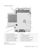
System Board Components 1 2 3 4 5 6 7 14 8 9 13 12 10 11 1 fan connector (FAN_FRONT) 2 internal speaker connector (INT_SPKR) 3 system board speaker (BEEP) 4 channel B memory connector (DIMM_2) 5 channel A memory connector (DIMM_1) 6 SATA data cable connector(SATA0) 7 standby power indicator (AUX_LED) Jumper Settings The jumper locations are shown below. 8 battery 9 clear CMOS jumper (RTCRST) 10 ...
System Board Components 1 2 3 4 5 6 7 14 8 9 13 12 10 11 1 fan connector (FAN_FRONT) 2 internal speaker connector (INT_SPKR) 3 system board speaker (BEEP) 4 channel B memory connector (DIMM_2) 5 channel A memory connector (DIMM_1) 6 SATA data cable connector(SATA0) 7 standby power indicator (AUX_LED) Jumper Settings The jumper locations are shown below. 8 battery 9 clear CMOS jumper (RTCRST) 10 ...
User Guide
Page 213
... and the computer. • Off - Ultra Small Form Factor Computer Specifications Microprocessor Microprocessor type Level 1 (L1) cache Level 2 (L2) cache Memory Type Memory connectors Memory modules supported Minimum memory Maximum memory BIOS address Computer Information Chipset Data bus width Address bus width DMA channels Interrupt levels BIOS chip (NVRAM...) Memory speed NIC Intel® Pentium® or Celeron® processor 32 KB 512-KB, 1-MB, or 2-MB pipelined-burst, ...
... and the computer. • Off - Ultra Small Form Factor Computer Specifications Microprocessor Microprocessor type Level 1 (L1) cache Level 2 (L2) cache Memory Type Memory connectors Memory modules supported Minimum memory Maximum memory BIOS address Computer Information Chipset Data bus width Address bus width DMA channels Interrupt levels BIOS chip (NVRAM...) Memory speed NIC Intel® Pentium® or Celeron® processor 32 KB 512-KB, 1-MB, or 2-MB pipelined-burst, ...

User Guide
Page 234
a Remove the memory module (see "Replacing/Adding Additional Memory") closest to the heat sink. b Press the release lever on its top, with the thermal grease facing upward. 4 Pull the release lever straight up until the heat sink is released, and then remove the processor from the processor. NOTICE: Lay the heat sink down on the retention base until the processor is released. 1 2 3 4 1 top of heat sink 2 heat sink 3 retention base 4 release lever c Gently lift the heat sink from the socket. 234 www.dell.com | support.dell.com 3 Remove the heat sink.
a Remove the memory module (see "Replacing/Adding Additional Memory") closest to the heat sink. b Press the release lever on its top, with the thermal grease facing upward. 4 Pull the release lever straight up until the heat sink is released, and then remove the processor from the processor. NOTICE: Lay the heat sink down on the retention base until the processor is released. 1 2 3 4 1 top of heat sink 2 heat sink 3 retention base 4 release lever c Gently lift the heat sink from the socket. 234 www.dell.com | support.dell.com 3 Remove the heat sink.

User Guide
Page 245
...configuration information after you add, change a user-selectable option such as the user password • To read the current amount of memory or set the type of hard drive installed Before you use system setup, it is divided into three areas: the options list, .... 2 When the blue DELL™ logo appears, press immediately. Information on (or restart) your computer and try again. Advanced Features 245 Disabling a Forgotten Password and Setting a New Password To reset system and/or administrator passwords, see the Microsoft® Windows® desktop. Entering System Setup 1 ...
...configuration information after you add, change a user-selectable option such as the user password • To read the current amount of memory or set the type of hard drive installed Before you use system setup, it is divided into three areas: the options list, .... 2 When the blue DELL™ logo appears, press immediately. Information on (or restart) your computer and try again. Advanced Features 245 Disabling a Forgotten Password and Setting a New Password To reset system and/or administrator passwords, see the Microsoft® Windows® desktop. Entering System Setup 1 ...
User Guide
Page 247
... Date/Time Boot Sequence Drives Diskette Drive Drive 0 through Drive 3 for the desktop, mini tower, and small form computers and Drive 0 though Drive 5 for the ultra small form factor computer. Indicates amount of installed memory, computer memory speed, amount of video memory, size of devices specified in its serial ATA native mode only. This...
... Date/Time Boot Sequence Drives Diskette Drive Drive 0 through Drive 3 for the desktop, mini tower, and small form computers and Drive 0 though Drive 5 for the ultra small form factor computer. Indicates amount of installed memory, computer memory speed, amount of video memory, size of devices specified in its serial ATA native mode only. This...

User Guide
Page 249
however, the BIOS will not recognize USB storage devices. Selects the mode of memory available to be noisier, but its performance is configured for IBM PS/2 compatibility EPP- port is not affected. This setting specifies the amount of ...factory default setting is configured for IBM AT compatibility PS/2 - USB Controller Front USB Ports LPT Port Mode LPT Port Address Video Primary Video Video Memory Size Performance Hyper-Threading HDD Acoustic Mode Enables and disables the integrated USB controller Off - Changing the acoustics setting does not alter your computer's processor...
however, the BIOS will not recognize USB storage devices. Selects the mode of memory available to be noisier, but its performance is configured for IBM PS/2 compatibility EPP- port is not affected. This setting specifies the amount of ...factory default setting is configured for IBM AT compatibility PS/2 - USB Controller Front USB Ports LPT Port Mode LPT Port Address Video Primary Video Video Memory Size Performance Hyper-Threading HDD Acoustic Mode Enables and disables the integrated USB controller Off - Changing the acoustics setting does not alter your computer's processor...

User Guide
Page 251
... Features 251 or leftarrow key to turn on when a Network Interface Controller or Remote Wakeup-capable modem receives a wake up remotely from Suspend. however, system memory remains active. Off - Intrusion Status This option appears in both the date and time fields. Select Clear to automatically turn on the computer. TPM security...
... Features 251 or leftarrow key to turn on when a Network Interface Controller or Remote Wakeup-capable modem receives a wake up remotely from Suspend. however, system memory remains active. Off - Intrusion Status This option appears in both the date and time fields. Select Clear to automatically turn on the computer. TPM security...

User Guide
Page 252
... want the computer to a USB device such as a floppy drive, memory key, or CD drive. The computer attempts to boot from the primary serial ATA hard drive. The computer attempts to boot from the CD drive. You can run the Dell Diagnostics on the bottom of the screen, press . 252 Advanced Features...
... want the computer to a USB device such as a floppy drive, memory key, or CD drive. The computer attempts to boot from the primary serial ATA hard drive. The computer attempts to boot from the CD drive. You can run the Dell Diagnostics on the bottom of the screen, press . 252 Advanced Features...


