User Guide
Page 12
... Tools and Utilities Dell Diagnostics 313 When to Use the Dell Diagnostics 313 Starting the Dell Diagnostics From Your Hard Drive . . . . 313 Starting the Dell Diagnostics From the Drivers and Utilities CD (Optional 313 Dell Diagnostics Main Menu 314 System Lights 316 Diagnostic Lights 317 Beep Codes 319 Error Messages 321 Resolving Software and Hardware Incompatibilities 325 Microsoft® Windows® XP 325 12 Contents
... Tools and Utilities Dell Diagnostics 313 When to Use the Dell Diagnostics 313 Starting the Dell Diagnostics From Your Hard Drive . . . . 313 Starting the Dell Diagnostics From the Drivers and Utilities CD (Optional 313 Dell Diagnostics Main Menu 314 System Lights 316 Diagnostic Lights 317 Beep Codes 319 Error Messages 321 Resolving Software and Hardware Incompatibilities 325 Microsoft® Windows® XP 325 12 Contents
User Guide
Page 15
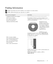
... for my computer • My computer documentation • My device documentation • Desktop System Software (DSS) Find It Here Drivers and Utilities CD (also known as a PDF at support.dell.com. Readme files may be included on your computer. NOTE: This document is available... to set up my computer • Basic troubleshooting information • How to run the Dell Diagnostics • Error codes and diagnostic lights • Tools and utilities • How to run the Dell Diagnostics or access your computer or in certain countries. Finding Information NOTE: Some features may not ...
... for my computer • My computer documentation • My device documentation • Desktop System Software (DSS) Find It Here Drivers and Utilities CD (also known as a PDF at support.dell.com. Readme files may be included on your computer. NOTE: This document is available... to set up my computer • Basic troubleshooting information • How to run the Dell Diagnostics • Error codes and diagnostic lights • Tools and utilities • How to run the Dell Diagnostics or access your computer or in certain countries. Finding Information NOTE: Some features may not ...

User Guide
Page 26
... in the Windows Device Manager. The power light illuminates and blinks or remains solid to attach a microphone. 26 Mini Tower Computer Use the microphone connector to indicate different operating modes: • No light - www.dell.com | support.dell.com 1 CD/DVD drive 2 floppy drive 3 USB 2.0 connectors (2) 4 LAN indicator light 5 diagnostic lights 6 power button 7 power light 8 hard-drive activity light 9 headphone...
... in the Windows Device Manager. The power light illuminates and blinks or remains solid to attach a microphone. 26 Mini Tower Computer Use the microphone connector to indicate different operating modes: • No light - www.dell.com | support.dell.com 1 CD/DVD drive 2 floppy drive 3 USB 2.0 connectors (2) 4 LAN indicator light 5 diagnostic lights 6 power button 7 power light 8 hard-drive activity light 9 headphone...
User Guide
Page 38
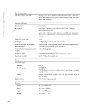
...Backup battery 305 W 1041 BTU/hr NOTE: Heat dissipation is calculated based upon the power supply wattage rating. See "Diagnostic Lights." Blinking green indicates sleep mode; manual selection power supplies-90 to 135 V at 50/60 Hz; 180 to run hard-drive ...solid amber indicates an internal power problem (see "Power Problems"). solid green indicates power-on integrated network adapter) Diagnostic lights Standby power light push button green light - www.dell.com | support.dell.com Key Combinations or displays a boot device menu that allows the user to enter a device for a single ...
...Backup battery 305 W 1041 BTU/hr NOTE: Heat dissipation is calculated based upon the power supply wattage rating. See "Diagnostic Lights." Blinking green indicates sleep mode; manual selection power supplies-90 to 135 V at 50/60 Hz; 180 to run hard-drive ...solid amber indicates an internal power problem (see "Power Problems"). solid green indicates power-on integrated network adapter) Diagnostic lights Standby power light push button green light - www.dell.com | support.dell.com Key Combinations or displays a boot device menu that allows the user to enter a device for a single ...

User Guide
Page 98
www.dell.com | support.dell.com 5 power light 6 diagnostic lights 7 hard-drive activity light 8 headphone connector 9 microphone connector 10 floppy drive 11 CD/DVD drive The power light illuminates and blinks or remains solid to attach a microphone. Use the lights to attach headphones and most kinds of light codes that can help you troubleshoot problems with your computer. This light flickers...
www.dell.com | support.dell.com 5 power light 6 diagnostic lights 7 hard-drive activity light 8 headphone connector 9 microphone connector 10 floppy drive 11 CD/DVD drive The power light illuminates and blinks or remains solid to attach a microphone. Use the lights to attach headphones and most kinds of light codes that can help you troubleshoot problems with your computer. This light flickers...
User Guide
Page 108
www.dell.com | support.dell.com Connectors Video 15-hole VGA connector Network adapter RJ45 connector... than from one of the devices in the system setup Boot Sequence option (during system start -up the Windows Security window; amber light - Blinking green indicates a sleep mode; Blinking amber indicates a problem with secondary serial two 6-pin mini-... menu that allows the user to enter a device for line-in Microsoft® Windows® XP, brings up only) as well as options to run harddrive and system diagnostics Controls and Lights Power control Power light push button green...
www.dell.com | support.dell.com Connectors Video 15-hole VGA connector Network adapter RJ45 connector... than from one of the devices in the system setup Boot Sequence option (during system start -up the Windows Security window; amber light - Blinking green indicates a sleep mode; Blinking amber indicates a problem with secondary serial two 6-pin mini-... menu that allows the user to enter a device for line-in Microsoft® Windows® XP, brings up only) as well as options to run harddrive and system diagnostics Controls and Lights Power control Power light push button green...
User Guide
Page 109
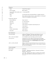
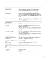
See "Diagnostic Lights." manual selection power supplies - 90 to 135 V at 50/60 Hz; 180 to 265 V at 50/60 Hz 3-V CR2032 lithium coin cell Physical Height Width ... 3 to 200 Hz at 1 octave/min 109 AUX_PWR on integrated network adapter) Diagnostic lights Standby power light green solid green light indicates network connection green light for 10-Mb operation; Controls and Lights Hard-drive access light Link light Link integrity light (on integrated network adapter) Activity light (on the system board Power DC power supply: Wattage Heat dissipation Voltage...
See "Diagnostic Lights." manual selection power supplies - 90 to 135 V at 50/60 Hz; 180 to 265 V at 50/60 Hz 3-V CR2032 lithium coin cell Physical Height Width ... 3 to 200 Hz at 1 octave/min 109 AUX_PWR on integrated network adapter) Diagnostic lights Standby power light green solid green light indicates network connection green light for 10-Mb operation; Controls and Lights Hard-drive access light Link light Link integrity light (on integrated network adapter) Activity light (on the system board Power DC power supply: Wattage Heat dissipation Voltage...
User Guide
Page 157
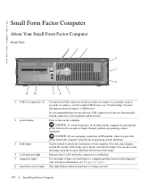
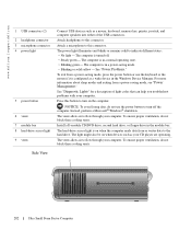
... NOTICE: To avoid losing data, do not turn the badge. www.dell.com | support.dell.com Small Form Factor Computer About Your Small Form Factor Computer Front View 1 2 3 4 5 6 11 10 98 7 1 USB 2.0 connectors (2) 2 power button 3 Dell badge 4 LAN indicator light 5 diagnostic lights 6 hard drive activity light Use the front USB connectors for devices that typically remain connected...
... NOTICE: To avoid losing data, do not turn the badge. www.dell.com | support.dell.com Small Form Factor Computer About Your Small Form Factor Computer Front View 1 2 3 4 5 6 11 10 98 7 1 USB 2.0 connectors (2) 2 power button 3 Dell badge 4 LAN indicator light 5 diagnostic lights 6 hard drive activity light Use the front USB connectors for devices that typically remain connected...
User Guide
Page 158
The computer is configured as a wake device in the Windows Device Manager. The computer is in a normal operating state. • Blinking green - Insert a CD or DVD (if applicable) into this drive. See "Power Problems." ... connector to attach headphones and most kinds of light codes that can help you troubleshoot problems with your computer. See "Diagnostic Lights" for any installed PCI and PCI Express cards. Plug serial, USB, and other devices into the appropriate connector. www.dell.com | support.dell.com 7 power light 8 headphone connector 9 microphone connector 10 floppy drive ...
The computer is configured as a wake device in the Windows Device Manager. The computer is in a normal operating state. • Blinking green - Insert a CD or DVD (if applicable) into this drive. See "Power Problems." ... connector to attach headphones and most kinds of light codes that can help you troubleshoot problems with your computer. See "Diagnostic Lights" for any installed PCI and PCI Express cards. Plug serial, USB, and other devices into the appropriate connector. www.dell.com | support.dell.com 7 power light 8 headphone connector 9 microphone connector 10 floppy drive ...
User Guide
Page 168
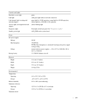
...dell.com | support.dell.com Controls and Lights Power light Hard-drive access light Link light Link integrity light (on integrated network adapter) Activity light (on the system board Power DC power supply: Wattage Heat dissipation Voltage Backup battery 275 W 939 BTU/hr NOTE: Heat dissipation is calculated based upon the power supply wattage rating. green solid green light...problem (see "Power Problems"). See "Diagnostic Lights." orange light for 10-Mb operation; yellow light for a 1000-Mb (1-Gb) operation yellow blinking light four lights on state. Blinking green indicates sleep ...
...dell.com | support.dell.com Controls and Lights Power light Hard-drive access light Link light Link integrity light (on integrated network adapter) Activity light (on the system board Power DC power supply: Wattage Heat dissipation Voltage Backup battery 275 W 939 BTU/hr NOTE: Heat dissipation is calculated based upon the power supply wattage rating. green solid green light...problem (see "Power Problems"). See "Diagnostic Lights." orange light for 10-Mb operation; yellow light for a 1000-Mb (1-Gb) operation yellow blinking light four lights on state. Blinking green indicates sleep ...
User Guide
Page 202
... normal operating state. • Blinking green - To ensure proper ventilation, do not block these cooling vents. See "Diagnostic Lights" for a description of the USB connectors. NOTICE: To avoid losing data, do not use the keyboard or the ...a Microsoft® Windows® shutdown. The computer is turned off the computer. The vents allow air to indicate different states: • No light - www.dell.com | support.dell.com 1 USB connectors (2) 2 headphone connector 3 microphone connector 4 power light 5 power button 6 vents 7 module bay 8 hard-drive access light 9 vents Connect...
... normal operating state. • Blinking green - To ensure proper ventilation, do not block these cooling vents. See "Diagnostic Lights" for a description of the USB connectors. NOTICE: To avoid losing data, do not use the keyboard or the ...a Microsoft® Windows® shutdown. The computer is turned off the computer. The vents allow air to indicate different states: • No light - www.dell.com | support.dell.com 1 USB connectors (2) 2 headphone connector 3 microphone connector 4 power light 5 power button 6 vents 7 module bay 8 hard-drive access light 9 vents Connect...

User Guide
Page 203
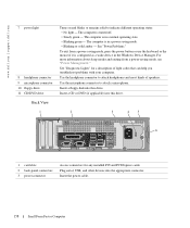
To ensure proper ventilation, do not block these cooling vents. 1 2 3 5 1 diagnostic lights 2 computer cover release knob 3 back-panel connectors 4 power connector 5 vents Back-Panel Connectors 4 See "Diagnostic Lights" for a description of the computer, allow air to flow through your computer. To ensure proper ventilation, do not block these cooling vents. 1 2 3 4 5 6 11 ... knob in a clockwise direction to flow through your computer. 1 vents Back View The vents, which are on each side of light codes that can help you troubleshoot problems with your computer.
To ensure proper ventilation, do not block these cooling vents. 1 2 3 5 1 diagnostic lights 2 computer cover release knob 3 back-panel connectors 4 power connector 5 vents Back-Panel Connectors 4 See "Diagnostic Lights" for a description of the computer, allow air to flow through your computer. To ensure proper ventilation, do not block these cooling vents. 1 2 3 4 5 6 11 ... knob in a clockwise direction to flow through your computer. 1 vents Back View The vents, which are on each side of light codes that can help you troubleshoot problems with your computer.
User Guide
Page 204
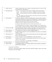
...monitor, plug the adapter cable into the white connector on " state. The connector for your network. See "Diagnostic Lights" for a description of light codes that the network cable has been securely attached. A good connection exists between a 1000-Mbps (1-Gbps)...speakers into the network connector. www.dell.com | support.dell.com 1 parallel connector 2 link integrity light 3 network adapter 4 network activity light 5 line-out connector 6 line-in connector 7 USB connectors (5) 8 serial connector 9 video connector 10 power connector 11 diagnostic lights Connect a parallel device, such ...
...monitor, plug the adapter cable into the white connector on " state. The connector for your network. See "Diagnostic Lights" for a description of light codes that the network cable has been securely attached. A good connection exists between a 1000-Mbps (1-Gbps)...speakers into the network connector. www.dell.com | support.dell.com 1 parallel connector 2 link integrity light 3 network adapter 4 network activity light 5 line-out connector 6 line-in connector 7 USB connectors (5) 8 serial connector 9 video connector 10 power connector 11 diagnostic lights Connect a parallel device, such ...

User Guide
Page 209
... align the four tabs with the four slots on the computer's back panel. 4 Insert the tabs into the slots and slide the piece toward the diagnostic lights (see the illustration) until the cable cover is securely positioned. 5 Install a security device in the security cable slot (optional). 1 Removing the Cable Cover 2 1 cable cover...
... align the four tabs with the four slots on the computer's back panel. 4 Insert the tabs into the slots and slide the piece toward the diagnostic lights (see the illustration) until the cable cover is securely positioned. 5 Install a security device in the security cable slot (optional). 1 Removing the Cable Cover 2 1 cable cover...
User Guide
Page 215
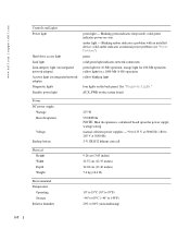
...) rather than from one of the devices in Microsoft® Windows® XP, brings up only) as well as options to run harddrive and system diagnostics Controls and Lights Power control Power light Power supply status light Hard-drive access light Link integrity light (on integrated network adapter) Activity light (on state. in MS-DOS® mode, restarts (reboots...
...) rather than from one of the devices in Microsoft® Windows® XP, brings up only) as well as options to run harddrive and system diagnostics Controls and Lights Power control Power light Power supply status light Hard-drive access light Link integrity light (on integrated network adapter) Activity light (on state. in MS-DOS® mode, restarts (reboots...
User Guide
Page 287
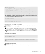
...keyboard to perform an operating system shutdown. Solving Problems 287 If the new keyboard works, the original keyboard is faulty. RUN THE DELL DIAGNOSTICS CHECK FOR SOFTWARE AND HARDWARE CONFLICTS Lockups and Software Problems CAUTION: Before you begin any of the procedures in this section, follow the... frayed cables. NOTE: You must use Microsoft® Windows® XP Service Pack 1 or later when you installed a unique image on your operating system, run the DSS utility. The computer does not start up CHECK THE DIAGNOSTIC LIGHTS ENSURE THAT THE POWER CABLE IS FIRMLY CONNECTED TO THE...
...keyboard to perform an operating system shutdown. Solving Problems 287 If the new keyboard works, the original keyboard is faulty. RUN THE DELL DIAGNOSTICS CHECK FOR SOFTWARE AND HARDWARE CONFLICTS Lockups and Software Problems CAUTION: Before you begin any of the procedures in this section, follow the... frayed cables. NOTE: You must use Microsoft® Windows® XP Service Pack 1 or later when you installed a unique image on your operating system, run the DSS utility. The computer does not start up CHECK THE DIAGNOSTIC LIGHTS ENSURE THAT THE POWER CABLE IS FIRMLY CONNECTED TO THE...

User Guide
Page 291
...NOT RESPONDING - Solving Problems 291 No connection speed light indicates that the network is functioning. Contact your network administrator or the person who set up your network settings are correct and that no network communication exists. RUN THE DELL DIAGNOSTICS CHECK FOR SOFTWARE AND HARDWARE CONFLICTS Network Problems .... CHECK THE NETWORK CABLE CONNECTOR - Replace the network cable. CHECK FOR SOFTWARE AND HARDWARE CONFLICTS Power Problems Fill out the Diagnostics Checklist as you complete these checks. See "Diagnostic Lights." IF THE POWER LIGHT IS BLINKING GREEN -
...NOT RESPONDING - Solving Problems 291 No connection speed light indicates that the network is functioning. Contact your network administrator or the person who set up your network settings are correct and that no network communication exists. RUN THE DELL DIAGNOSTICS CHECK FOR SOFTWARE AND HARDWARE CONFLICTS Network Problems .... CHECK THE NETWORK CABLE CONNECTOR - Replace the network cable. CHECK FOR SOFTWARE AND HARDWARE CONFLICTS Power Problems Fill out the Diagnostics Checklist as you complete these checks. See "Diagnostic Lights." IF THE POWER LIGHT IS BLINKING GREEN -

User Guide
Page 297
...TEST THE ELECTRICAL OUTLET - If the new monitor works, the original monitor is normal for more information. Video and Monitor Problems Fill out the Diagnostics Checklist as a lamp. CAUTION: Before you complete these checks. Exit system setup and restart your computer). • If you are using the...the computer and monitor power cables to ensure that Primary Video option is lit or blinking, the monitor has power. CHECK THE DIAGNOSTIC LIGHTS CHECK THE CARD SETTING -Enter system setup and ensure that the monitor is working monitor to have missing pins.) CHECK THE MONITOR POWER...
...TEST THE ELECTRICAL OUTLET - If the new monitor works, the original monitor is normal for more information. Video and Monitor Problems Fill out the Diagnostics Checklist as a lamp. CAUTION: Before you complete these checks. Exit system setup and restart your computer). • If you are using the...the computer and monitor power cables to ensure that Primary Video option is lit or blinking, the monitor has power. CHECK THE DIAGNOSTIC LIGHTS CHECK THE CARD SETTING -Enter system setup and ensure that the monitor is working monitor to have missing pins.) CHECK THE MONITOR POWER...
User Guide
Page 316
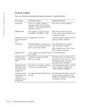
...; Windows® XP). On the desktop computer, a solid green light indicates a network connection. www.dell.com | support.dell.com System Lights Your power button light and hard-drive light may be faulty. Solid green power light and no beep code and no beep code but the computer locks up during POST An integrated system board device may Check the diagnostic lights to...
...; Windows® XP). On the desktop computer, a solid green light indicates a network connection. www.dell.com | support.dell.com System Lights Your power button light and hard-drive light may be faulty. Solid green power light and no beep code and no beep code but the computer locks up during POST An integrated system board device may Check the diagnostic lights to...

User Guide
Page 317
... help you begin any of the procedures in this section, follow the safety instructions located in the recovery mode. The diagnostic lights can be off " condition, or a possible pre-BIOS failure has occurred. If the computer malfunctions during the POST process, the pattern displayed ...on the LEDs may vary depending on the front or back panel. The diagnostic lights are not lit after the computer successfully boots to the operating system. the computer is in the process the computer halted. When the computer ...
... help you begin any of the procedures in this section, follow the safety instructions located in the recovery mode. The diagnostic lights can be off " condition, or a possible pre-BIOS failure has occurred. If the computer malfunctions during the POST process, the pattern displayed ...on the LEDs may vary depending on the front or back panel. The diagnostic lights are not lit after the computer successfully boots to the operating system. the computer is in the process the computer halted. When the computer ...


