
User's Guide
Page 3
... Instructions 9 General 9 When Using Your Computer 11 When Working Inside Your Computer 12 Protecting Against Electrostatic Discharge 13 Ergonomic Computing Habits 13 Battery Disposal 14 1 About Your Computer Finding Information and Assistance 16 Front Panel 19 Front Panel Door 22 Speaker/Headphone Connector 23 Power Button 23 Power Light 25 Floppy Drive Access Light 26 Hard Drive Access Light 26 Back Panel 26 Connecting Devices 29 Parallel Connector 30 Mouse Connector 30 USB Connectors 30 Integrated Network Adapter Connector 30 Network Cable Requirements...
... Instructions 9 General 9 When Using Your Computer 11 When Working Inside Your Computer 12 Protecting Against Electrostatic Discharge 13 Ergonomic Computing Habits 13 Battery Disposal 14 1 About Your Computer Finding Information and Assistance 16 Front Panel 19 Front Panel Door 22 Speaker/Headphone Connector 23 Power Button 23 Power Light 25 Floppy Drive Access Light 26 Hard Drive Access Light 26 Back Panel 26 Connecting Devices 29 Parallel Connector 30 Mouse Connector 30 USB Connectors 30 Integrated Network Adapter Connector 30 Network Cable Requirements...

User's Guide
Page 8
... Only 244 Polish Center for Warranty Repair or Credit 214 Before You Call 215 Contacting Dell 217 8 Additional Information Regulatory Notices 236 FCC Notices (U.S. Device Drivers 208 Memory-Resident Programs 208 Program Conflicts 209 Memory Address Conflicts 209 Interrupt Assignment Conflicts 209 7 Getting Help Technical Assistance 212 Online Services 212 AutoTech Service 213 Automated Order-Status Service 214 Technical Support Service 214 Problems With Your...
... Only 244 Polish Center for Warranty Repair or Credit 214 Before You Call 215 Contacting Dell 217 8 Additional Information Regulatory Notices 236 FCC Notices (U.S. Device Drivers 208 Memory-Resident Programs 208 Program Conflicts 209 Memory Address Conflicts 209 Interrupt Assignment Conflicts 209 7 Getting Help Technical Assistance 212 Online Services 212 AutoTech Service 213 Automated Order-Status Service 214 Technical Support Service 214 Problems With Your...
User's Guide
Page 13
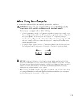
... power supply do not have a voltage selection switch on ) removed. • Your computer is connected to operate at the correct operating voltage. NOTICE: To help avoid damaging a computer with the AC power available in your location. • Before working inside the computer, unplug the computer to receive power any time the computer is equipped with any cover(s) (including computer covers, bezels, filler brackets, front-panel...
... power supply do not have a voltage selection switch on ) removed. • Your computer is connected to operate at the correct operating voltage. NOTICE: To help avoid damaging a computer with the AC power available in your location. • Before working inside the computer, unplug the computer to receive power any time the computer is equipped with any cover(s) (including computer covers, bezels, filler brackets, front-panel...

User's Guide
Page 18
... on the ResourceCD that Dell provides as support tools. You can use this CD to run diagnostics tools. Resources and Support Tools Resources Contents Dell OptiPlex ResourceCD • Dell Diagnostics • Drivers • Utilities • Computer and device documentation Setup and Quick Reference Guide • Getting started/setup • Support tools • Solving Problems Using the Resource See the main menu on using support resources • Diagnosing a problem • Using tools and utilities 16 About Yo ur...
... on the ResourceCD that Dell provides as support tools. You can use this CD to run diagnostics tools. Resources and Support Tools Resources Contents Dell OptiPlex ResourceCD • Dell Diagnostics • Drivers • Utilities • Computer and device documentation Setup and Quick Reference Guide • Getting started/setup • Support tools • Solving Problems Using the Resource See the main menu on using support resources • Diagnosing a problem • Using tools and utilities 16 About Yo ur...
User's Guide
Page 31
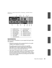
...specific installation and configuration instructions. Also, external devices like a mouse or printer usually require you connect external devices to your computer is turned off. I /O) connector to operate properly. For example, you must connect most devices to a particular input/output (I /O Panel-Small Form-Factor, Desktop, and Mini-Tower Computers 1 23 4 56 7 8 9 10 11 12 13 1 parallel connector 2 keyboard connector 3 mouse connector 4 link integrity light 5 network adapter 6 activity light 7 serial connector (1) 8 serial connector (2) 9 diagnostic lights 10 USB connectors...
...specific installation and configuration instructions. Also, external devices like a mouse or printer usually require you connect external devices to your computer is turned off. I /O) connector to operate properly. For example, you must connect most devices to a particular input/output (I /O Panel-Small Form-Factor, Desktop, and Mini-Tower Computers 1 23 4 56 7 8 9 10 11 12 13 1 parallel connector 2 keyboard connector 3 mouse connector 4 link integrity light 5 network adapter 6 activity light 7 serial connector (1) 8 serial connector (2) 9 diagnostic lights 10 USB connectors...
User's Guide
Page 32
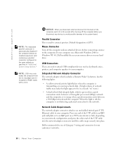
..., depending on your hard drive. Mouse Connector Turn off the computer and any devices to avoid possible damage to the system board. Dell recommends the use of network traffic may make this light appear to be in "Additional System Setup Options." Press one end of the UTP cable into the network adapter connector until the cable snaps securely into place. Integrated Network Adapter Connector The network adapter, which is green when a good connection exists between...
..., depending on your hard drive. Mouse Connector Turn off the computer and any devices to avoid possible damage to the system board. Dell recommends the use of network traffic may make this light appear to be in "Additional System Setup Options." Press one end of the UTP cable into the network adapter connector until the cable snaps securely into place. Integrated Network Adapter Connector The network adapter, which is green when a good connection exists between...
User's Guide
Page 49
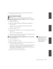
... and devices to assign a new password. 4 If you want to an electrical outlet, and then turn them on the system board. 3 Close the computer cover. 4 Reconnect your computer with the PSWD jumper installed reenables the password feature. NOTE: Before you assign a new system and/or setup password, you must replace the PSWD jumper plug to assign a new setup password, perform the steps in "Assigning a System Password." See "Jumper Settings" to locate the password jumper...
... and devices to assign a new password. 4 If you want to an electrical outlet, and then turn them on the system board. 3 Close the computer cover. 4 Reconnect your computer with the PSWD jumper installed reenables the password feature. NOTE: Before you assign a new system and/or setup password, you must replace the PSWD jumper plug to assign a new setup password, perform the steps in "Assigning a System Password." See "Jumper Settings" to locate the password jumper...
User's Guide
Page 55
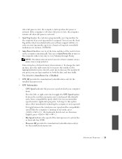
... 53 The default for Auto Power On is restored. You can set the time and days of the microprocessor's system bus, or front-side bus (FSB). - CPU Speed indicates the processor speed at which is included with your software support utilities, to enter an asset tag number up when AC power is Disabled. • CPU ID provides the manufacturer's identification code for the installed microprocessor. You can type numbers in...
... 53 The default for Auto Power On is restored. You can set the time and days of the microprocessor's system bus, or front-side bus (FSB). - CPU Speed indicates the processor speed at which is included with your software support utilities, to enter an asset tag number up when AC power is Disabled. • CPU ID provides the manufacturer's identification code for the installed microprocessor. You can type numbers in...

User's Guide
Page 57
... you are running the Microsoft® Windows® 95 or IBM® OS/2® operating system, you set a serial connector to Auto and add an expansion card containing a connector configured to the same designation, the computer automatically remaps the integrated port to the next available connector designation that came with COM3, is set I /O address used to control the use of device connected to disable the connector. - I/O Address: This option determines the...
... you are running the Microsoft® Windows® 95 or IBM® OS/2® operating system, you set a serial connector to Auto and add an expansion card containing a connector configured to the same designation, the computer automatically remaps the integrated port to the next available connector designation that came with COM3, is set I /O address used to control the use of device connected to disable the connector. - I/O Address: This option determines the...

User's Guide
Page 60
... the following settings identify the type of IDE devices installed in system setup. For example, if it finds that use this setting for each option, press to set the appropriate Drive option to Auto. Primary Master: IDE Disk Drive Secondary Master: CD-ROM Reader If it detects a device during the scan, it sets the device setting to Auto in any hard drive field to access the field's pop-up settings menu. If no device is connected to...
... the following settings identify the type of IDE devices installed in system setup. For example, if it finds that use this setting for each option, press to set the appropriate Drive option to Auto. Primary Master: IDE Disk Drive Secondary Master: CD-ROM Reader If it detects a device during the scan, it sets the device setting to Auto in any hard drive field to access the field's pop-up settings menu. If no device is connected to...

User's Guide
Page 79
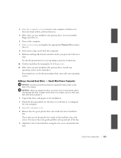
... installed a sound card, perform the following steps: a Enter system setup, select Integrated Devices and change the setting for Sound to Off. 16 Connect external audio devices to the sound card's connectors. Before removing a component from their electrical outlets, and wait 10 to 20 seconds. 2 Open the computer cover. 3 In the small desktop computer, remove the expansion-card cage. Do not connect external audio devices to the microphone, speaker/headphone, or line-in network adapter's connectors. Do not connect the network cable to Enabled or Enabled...
... installed a sound card, perform the following steps: a Enter system setup, select Integrated Devices and change the setting for Sound to Off. 16 Connect external audio devices to the sound card's connectors. Before removing a component from their electrical outlets, and wait 10 to 20 seconds. 2 Open the computer cover. 3 In the small desktop computer, remove the expansion-card cage. Do not connect external audio devices to the microphone, speaker/headphone, or line-in network adapter's connectors. Do not connect the network cable to Enabled or Enabled...
User's Guide
Page 125
.... 3 Open the computer cover. 4 Remove the two green plastic drive rails inside of the hard-drive bay with your operating system. 4 Close the computer cover, reconnect your computer and devices to their electrical outlets, and turn them on. 5 If the drive you just installed is the primary drive, insert a bootable floppy into drive A. 6 Turn on the computer. 7 Enter system setup, and update the appropriate Primary Drive option (0 or 1). 8 Exit system setup, and reboot...
.... 3 Open the computer cover. 4 Remove the two green plastic drive rails inside of the hard-drive bay with your operating system. 4 Close the computer cover, reconnect your computer and devices to their electrical outlets, and turn them on. 5 If the drive you just installed is the primary drive, insert a bootable floppy into drive A. 6 Turn on the computer. 7 Enter system setup, and update the appropriate Primary Drive option (0 or 1). 8 Exit system setup, and reboot...
User's Guide
Page 167
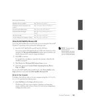
... system configuration is displayed on the screen. If you are using the Dell OptiPlex ResourceCD, perform the following steps: 1 Insert the Dell OptiPlex ResourceCD into the CD drive. NOTE: To access device drivers and user documentation, you must use the Dell OptiPlex ResourceCD while you are running the Microsoft® Windows® operating system, perform the following steps: 1 Click My Drivers in the Topic pull-down menu. To access the Dell OptiPlex ResourceCD Guide, click User's Guides in...
... system configuration is displayed on the screen. If you are using the Dell OptiPlex ResourceCD, perform the following steps: 1 Insert the Dell OptiPlex ResourceCD into the CD drive. NOTE: To access device drivers and user documentation, you must use the Dell OptiPlex ResourceCD while you are running the Microsoft® Windows® operating system, perform the following steps: 1 Click My Drivers in the Topic pull-down menu. To access the Dell OptiPlex ResourceCD Guide, click User's Guides in...
User's Guide
Page 200
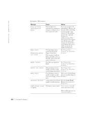
... problem persists, see "Battery Problems." 198 Solving Problems The computer could not find a specific drive, try another floppy in your computer off the power and reinsert one or more expansion cards. drive. The disk reset operation failed. Enter system setup and correct the date or time. If the message does not reappear, turn off and unplug it . www.dell.com | support.dell.com Computer Messages Message Plug and Play Configuration Error...
... problem persists, see "Battery Problems." 198 Solving Problems The computer could not find a specific drive, try another floppy in your computer off the power and reinsert one or more expansion cards. drive. The disk reset operation failed. Enter system setup and correct the date or time. If the message does not reappear, turn off and unplug it . www.dell.com | support.dell.com Computer Messages Message Plug and Play Configuration Error...
User's Guide
Page 202
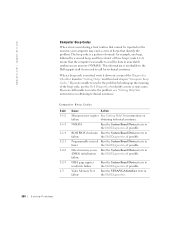
... Dell Diagnostics, if possible. Direct memory access Run the System Board Devices tests in the Dell Diagnostics. 200 Solving Problems If you need to resolve the problem, see "Getting Help" for instructions on obtaining technical assistance. Computer Beep Codes Code 1-1-2 1-1-3 1-1-4 1-2-1 1-2-2 1-2-3 1-3 Cause Action Microprocessor register See Getting Help" for instructions on failure obtaining technical assistance. This information is emitted, write it up in timer the Dell Diagnostics, if possible. Video Memory Test failure Run the VESA/VGA Interface...
... Dell Diagnostics, if possible. Direct memory access Run the System Board Devices tests in the Dell Diagnostics. 200 Solving Problems If you need to resolve the problem, see "Getting Help" for instructions on obtaining technical assistance. Computer Beep Codes Code 1-1-2 1-1-3 1-1-4 1-2-1 1-2-2 1-2-3 1-3 Cause Action Microprocessor register See Getting Help" for instructions on failure obtaining technical assistance. This information is emitted, write it up in timer the Dell Diagnostics, if possible. Video Memory Test failure Run the VESA/VGA Interface...

User's Guide
Page 205
... supply may result. See "Software Problems" and the documentation that each board may be faulty or microprocessor is properly is correct. If the computer does not boot, see "Getting Help" for instructions on diagnosing the beep code. CAUTION: Before servicing any components inside your computer fail to operate, lights on the front panel and back panel of the diagnostic codes. Diagnostics Messages When you troubleshoot a computer problem. These particular error...
... supply may result. See "Software Problems" and the documentation that each board may be faulty or microprocessor is properly is correct. If the computer does not boot, see "Getting Help" for instructions on diagnosing the beep code. CAUTION: Before servicing any components inside your computer fail to operate, lights on the front panel and back panel of the diagnostic codes. Diagnostics Messages When you troubleshoot a computer problem. These particular error...

User's Guide
Page 212
... is full Used by interrupt controller 1 to enable IRQ8 through IRQ15 Used by serial connector 2 Used by serial connector 1 Available Used by the floppy/tape drive controller Used by the parallel port Used by the real-time clock (RTC) Used by the video graphics array (VGA) interface (optional) Available Available Used by the mouse port Used by the math coprocessor (if applicable) Used by the primary integrated drive electronics (IDE) controller Used by the secondary IDE controller 210 Solving Problems
... is full Used by interrupt controller 1 to enable IRQ8 through IRQ15 Used by serial connector 2 Used by serial connector 1 Available Used by the floppy/tape drive controller Used by the parallel port Used by the real-time clock (RTC) Used by the video graphics array (VGA) interface (optional) Available Available Used by the mouse port Used by the math coprocessor (if applicable) Used by the primary integrated drive electronics (IDE) controller Used by the secondary IDE controller 210 Solving Problems

User's Guide
Page 227
Country (City) International Access Code Country Code City Code Department Name or Service Area, Website and E-Mail Address Japan (Kawasaki) Website: support.jp.dell.com International Access Code: 001 Technical Support (servers) Country Code: 81 Technical Support outside of Japan (servers) City Code: 44 Technical Support (Dimension™ and Inspiron™) Technical Support outside of Japan (Dimension and Inspiron) Technical Support (Dell Precision™, OptiPlex™, and Latitude™) Technical Support outside of Japan (Dell Precision, OptiPlex, and Latitude) 24-Hour ...
Country (City) International Access Code Country Code City Code Department Name or Service Area, Website and E-Mail Address Japan (Kawasaki) Website: support.jp.dell.com International Access Code: 001 Technical Support (servers) Country Code: 81 Technical Support outside of Japan (servers) City Code: 44 Technical Support (Dimension™ and Inspiron™) Technical Support outside of Japan (Dimension and Inspiron) Technical Support (Dell Precision™, OptiPlex™, and Latitude™) Technical Support outside of Japan (Dell Precision, OptiPlex, and Latitude) 24-Hour ...
User's Guide
Page 264
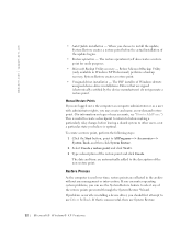
... update begins. • Restore operation - Before Microsoft Backup Utility (only available in the archive without any of user accounts, see "How to Add Users.") This is optimal. The INF installer of the new restore point. Drivers that is used over time, restore points are signed (electronically certified by the device manufacturer) do not generate a restore point. To create a restore point, perform the following steps: 1 Click the Start button...
... update begins. • Restore operation - Before Microsoft Backup Utility (only available in the archive without any of user accounts, see "How to Add Users.") This is optimal. The INF installer of the new restore point. Drivers that is used over time, restore points are signed (electronically certified by the device manufacturer) do not generate a restore point. To create a restore point, perform the following steps: 1 Click the Start button...
User's Guide
Page 274
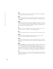
... be updated, or "flashed," which an application program accesses the OS and other drives with digital electronics and logic. An IBM® PC introduced in the BIOS. A specification for Information Interchange. System setup allows you to convey some control codes, the space character, numbers, most basic punctuation, and unaccented lower- ASCII can correct errors, support new hardware, and so on a ROM chip. and upper-case letters...
... be updated, or "flashed," which an application program accesses the OS and other drives with digital electronics and logic. An IBM® PC introduced in the BIOS. A specification for Information Interchange. System setup allows you to convey some control codes, the space character, numbers, most basic punctuation, and unaccented lower- ASCII can correct errors, support new hardware, and so on a ROM chip. and upper-case letters...


