
Owner's Manual
Page 41
..., adjust the volume, bass, or treble to check for instructions. If your screen. R E I N S T A L L T H E S C A N N E R D R I N D O W S V O L U M E C O N T R O L - If you did not turn the player volume down or off nearby fans, fluorescent lights, or halogen lamps to eliminate distortion. A D J U S T T H E W I V E R - Sound from speakers NOTE: The volume control in the Product Information Guide. Solving Problems 41
..., adjust the volume, bass, or treble to check for instructions. If your screen. R E I N S T A L L T H E S C A N N E R D R I N D O W S V O L U M E C O N T R O L - If you did not turn the player volume down or off nearby fans, fluorescent lights, or halogen lamps to eliminate distortion. A D J U S T T H E W I V E R - Sound from speakers NOTE: The volume control in the Product Information Guide. Solving Problems 41

Owner's Manual
Page 43
... is at least 60 cm (2 ft) away from the monitor. Ensure that the subwoofer is working by testing it with another device, such as a lamp. Fans, fluorescent lights, halogen lamps, and other electrical devices can cause the screen image to read C H E C K T H E M O N I T O R S E T T I N G S - C H E C K T H E D I A G N O S T I C L I T O R A W A Y F R O M E X T E R N A L P O W E R S O U R C E S - M O V E T H E S U B W O O F E R A W A Y F R O M T H E M O N I C A L O U T L E T - Solving Problems 43 See the monitor documentation for Screen resolution...
... is at least 60 cm (2 ft) away from the monitor. Ensure that the subwoofer is working by testing it with another device, such as a lamp. Fans, fluorescent lights, halogen lamps, and other electrical devices can cause the screen image to read C H E C K T H E M O N I T O R S E T T I N G S - C H E C K T H E D I A G N O S T I C L I T O R A W A Y F R O M E X T E R N A L P O W E R S O U R C E S - M O V E T H E S U B W O O F E R A W A Y F R O M T H E M O N I C A L O U T L E T - Solving Problems 43 See the monitor documentation for Screen resolution...
Owner's Manual
Page 63
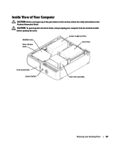
CAUTION: To guard against electrical shock, always unplug your computer from the electrical outlet before opening the cover. Inside View of Your Computer CAUTION: Before you begin any of the procedures in this section, follow the safety instructions in the Product Information Guide. CD/DVD drive drive release latch power supply and fan hard drive front-panel door power button heat sink assembly Removing and Installing Parts 63
CAUTION: To guard against electrical shock, always unplug your computer from the electrical outlet before opening the cover. Inside View of Your Computer CAUTION: Before you begin any of the procedures in this section, follow the safety instructions in the Product Information Guide. CD/DVD drive drive release latch power supply and fan hard drive front-panel door power button heat sink assembly Removing and Installing Parts 63
Owner's Manual
Page 64
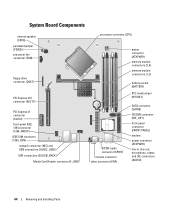
System Board Components internal speaker (SPKR) password jumper (PSWD) processor fan connector (FAN) floppy drive connector (DSKT) PCI Express x16 connector (SLOT1) PCI Express x1 connector (SLOT2) front-panel IEEE 1394 connector (1394_FRONT) IEEE 1394 connector (1394_CON) network ...
System Board Components internal speaker (SPKR) password jumper (PSWD) processor fan connector (FAN) floppy drive connector (DSKT) PCI Express x16 connector (SLOT1) PCI Express x1 connector (SLOT2) front-panel IEEE 1394 connector (1394_FRONT) IEEE 1394 connector (1394_CON) network ...

Owner's Manual
Page 81
... computer chassis. Removing and Installing Parts 81 4 Check all cable connections, and fold cables out of the way to provide airflow for the fan and cooling vents. 5 Replace the computer cover (see page 93). 6 Connect your computer and devices to components inside your computer, discharge static...any of the procedures in this section, follow the safety instructions located in the Product Information Guide. You can do so by running the Dell Diagnostics (see page 99) and select the appropriate Drive option. Verify that came with the drive for drive operation. 8 Enter system setup...
... computer chassis. Removing and Installing Parts 81 4 Check all cable connections, and fold cables out of the way to provide airflow for the fan and cooling vents. 5 Replace the computer cover (see page 93). 6 Connect your computer and devices to components inside your computer, discharge static...any of the procedures in this section, follow the safety instructions located in the Product Information Guide. You can do so by running the Dell Diagnostics (see page 99) and select the appropriate Drive option. Verify that came with the drive for drive operation. 8 Enter system setup...

Owner's Manual
Page 88
...their electrical outlets, and turn them on installing any software required for instructions on . See the documentation that your computer works correctly by running the Dell Diagnostics (see page 48). 88 Removing and Installing Parts NOTICE: To connect a network cable, first plug the cable in to the network device ...and then plug it in to the computer. 7 Connect your computer and devices to provide airflow for the fan and cooling vents. 5 Replace the CD/DVD drive (see page 80). 6 Replace the computer cover (see page 99) and select the appropriate ...
...their electrical outlets, and turn them on installing any software required for instructions on . See the documentation that your computer works correctly by running the Dell Diagnostics (see page 48). 88 Removing and Installing Parts NOTICE: To connect a network cable, first plug the cable in to the network device ...and then plug it in to the computer. 7 Connect your computer and devices to provide airflow for the fan and cooling vents. 5 Replace the CD/DVD drive (see page 80). 6 Replace the computer cover (see page 99) and select the appropriate ...

Owner's Manual
Page 97
...; supports front-panel IEEE1394 port Appendix 97 Connectors External connectors: IEEE 1394 Video USB Audio Network adapter Modem System board connectors: IDE drive Serial ATA Fan PCI Express x1 PCI Express x16 USB MDC Floppy connector Front panel Power Processor power IEEE 1394 one 6-pin powered back-panel connector one 6-pin...
...; supports front-panel IEEE1394 port Appendix 97 Connectors External connectors: IEEE 1394 Video USB Audio Network adapter Modem System board connectors: IDE drive Serial ATA Fan PCI Express x1 PCI Express x16 USB MDC Floppy connector Front panel Power Processor power IEEE 1394 one 6-pin powered back-panel connector one 6-pin...
Service Manual
Page 15
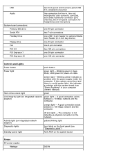
... light, this indicates a problem with the power supply inside the computer. USB Audio System board connectors: Primary IDE drive Serial ATA FlexBay Drive Floppy drive Fan PCI 2.3 PCI Express x1 PCI Express x16 two front-panel and five back-panel USB 2.0-compliant connectors five connectors for line-in sleep state; Blinking...
... light, this indicates a problem with the power supply inside the computer. USB Audio System board connectors: Primary IDE drive Serial ATA FlexBay Drive Floppy drive Fan PCI 2.3 PCI Express x1 PCI Express x16 two front-panel and five back-panel USB 2.0-compliant connectors five connectors for line-in sleep state; Blinking...
Service Manual
Page 18
Back to Contents Page Removing and Installing Parts Dell™ Dimension™ 5150/E510 Service Manual Memory Cards Drive Panel Front Panel Drives Hard Drive Floppy Drive Media Card Reader (Optional) CD/DVD Drive Heat Sink Assembly Processor Fan Assembly Front I/O Panel System Board Power Supply Memory You can increase your Owner's Manual. If...
Back to Contents Page Removing and Installing Parts Dell™ Dimension™ 5150/E510 Service Manual Memory Cards Drive Panel Front Panel Drives Hard Drive Floppy Drive Media Card Reader (Optional) CD/DVD Drive Heat Sink Assembly Processor Fan Assembly Front I/O Panel System Board Power Supply Memory You can increase your Owner's Manual. If...
Service Manual
Page 41
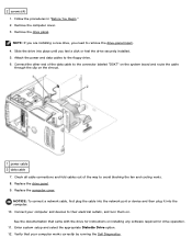
Connect your computer works correctly by running the Dell Diagnostics. Verify that came with the drive for instructions on the shroud. 1 power cable 2 data cable 7. Attach the power and data cables to avoid blocking the fan and cooling vents. 8. Replace the computer cover. Check all cable connections and fold cables out of the...
Connect your computer works correctly by running the Dell Diagnostics. Verify that came with the drive for instructions on the shroud. 1 power cable 2 data cable 7. Attach the power and data cables to avoid blocking the fan and cooling vents. 8. Replace the computer cover. Check all cable connections and fold cables out of the...

Service Manual
Page 47
Check all cable connections, and fold cables out of the way to their electrical outlets, and turn them on installing any software required for instructions on . Replace the drive panel. 8. Replace the computer cover. See the documentation that came with the drive for drive operation. Connect your computer and devices to avoid blocking the fan and cooling vents. 7. NOTICE: To connect a network cable, first plug the cable into the network port or device and then plug it into the computer. 9. 5. Connect the power and data cables to the drive. 6.
Check all cable connections, and fold cables out of the way to their electrical outlets, and turn them on installing any software required for instructions on . Replace the drive panel. 8. Replace the computer cover. See the documentation that came with the drive for drive operation. Connect your computer and devices to avoid blocking the fan and cooling vents. 7. NOTICE: To connect a network cable, first plug the cable into the network port or device and then plug it into the computer. 9. 5. Connect the power and data cables to the drive. 6.

Service Manual
Page 52
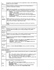
... to components inside your computer's electronic components. Removing the Fan Assembly 1. Press the release tab on the fan-cable connector on the system board to electrical outlets, and turn them on fan cable connector 5. Fan Assembly CAUTION: Before you touch any of your computer, ... and devices to remove the connector. 1 fan release tabs (2) 2 fan assembly 3 fan cable connector 4 release tab on . Remove the computer cover. 3. 10. Simultaneously press the fan-release tab on one side of the fan assembly and pull the fan-release tab located on the computer chassis....
... to components inside your computer's electronic components. Removing the Fan Assembly 1. Press the release tab on the fan-cable connector on the system board to electrical outlets, and turn them on fan cable connector 5. Fan Assembly CAUTION: Before you touch any of your computer, ... and devices to remove the connector. 1 fan release tabs (2) 2 fan assembly 3 fan cable connector 4 release tab on . Remove the computer cover. 3. 10. Simultaneously press the fan-release tab on one side of the fan assembly and pull the fan-release tab located on the computer chassis....
Service Manual
Page 53
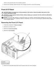
... front of the procedures in this section, follow the safety instructions in "Before You Begin." 2. Follow the procedures in the Product Information Guide. Remove the fan assembly. 1 screw 2 front I /O Panel 1. NOTICE: To prevent static damage to components inside your computer, discharge static electricity from the electrical outlet before you begin any...
... front of the procedures in this section, follow the safety instructions in "Before You Begin." 2. Follow the procedures in the Product Information Guide. Remove the fan assembly. 1 screw 2 front I /O Panel 1. NOTICE: To prevent static damage to components inside your computer, discharge static electricity from the electrical outlet before you begin any...
Service Manual
Page 68
.... Power Management Determines how the system responds when AC power is re-applied. On - Auto Power On (Off Sets the computer to modify the processor fan and speed based on when power is re-applied after a power loss. The system turns on SpeedStep processor temperature readings. (On default) NOTE: Intel SpeedStep...
.... Power Management Determines how the system responds when AC power is re-applied. On - Auto Power On (Off Sets the computer to modify the processor fan and speed based on when power is re-applied after a power loss. The system turns on SpeedStep processor temperature readings. (On default) NOTE: Intel SpeedStep...


