Owner's Manual
Page 4
... crashes repeatedly 37 A program is designed for an earlier Microsoft® Windows® operating system 37 A solid blue screen appears 37 Other software problems 38 Memory Problems 38 Mouse Problems 39 Network Problems 40 Power Problems 40 4 Contents
... crashes repeatedly 37 A program is designed for an earlier Microsoft® Windows® operating system 37 A solid blue screen appears 37 Other software problems 38 Memory Problems 38 Mouse Problems 39 Network Problems 40 Power Problems 40 4 Contents
Owner's Manual
Page 6
System Board Components 67 Memory 68 DDR2 Memory Overview 68 Addressing Memory With 4-GB Configurations 69 Installing Memory 69 Removing Memory 71 Cards 72 PCI Cards 72 PCI Express Cards 76 Drive Panel 80 Removing the Drive Panel 80 Removing the Drive-Panel Insert 81 Replacing ...
System Board Components 67 Memory 68 DDR2 Memory Overview 68 Addressing Memory With 4-GB Configurations 69 Installing Memory 69 Removing Memory 71 Cards 72 PCI Cards 72 PCI Express Cards 76 Drive Panel 80 Removing the Drive Panel 80 Removing the Drive-Panel Insert 81 Replacing ...
Owner's Manual
Page 10
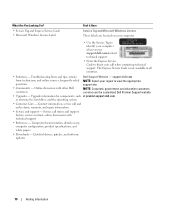
as memory, the hard drive, and the operating system • Customer Care - Computer documentation, details on your computer. • Use the Service Tag to identify your computer when you use the customized Dell Premier Support website • Upgrades - Online discussion with technical... information, service call status and support history, service contract, online discussions with other Dell NOTE: Corporate, government, and education customers customers can also use support.dell.comorcontact technical support. • Enter the Express Service Code to direct your call when...
as memory, the hard drive, and the operating system • Customer Care - Computer documentation, details on your computer. • Use the Service Tag to identify your computer when you use the customized Dell Premier Support website • Upgrades - Online discussion with technical... information, service call status and support history, service contract, online discussions with other Dell NOTE: Corporate, government, and education customers customers can also use support.dell.comorcontact technical support. • Enter the Express Service Code to direct your call when...
Owner's Manual
Page 17
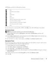
... 800 by 600 pixels. 5 Click the drop-down to increase or decrease the volume. Adjusting the Volume NOTE: When the speakers are using too much memory and preventing DVD playback, adjust the display properties: 1 Click the Start button and click Control Panel. 2 Under Pick a category, click Appearance and Themes. 3 Under Pick...
... 800 by 600 pixels. 5 Click the drop-down to increase or decrease the volume. Adjusting the Volume NOTE: When the speakers are using too much memory and preventing DVD playback, adjust the display properties: 1 Click the Start button and click Control Panel. 2 Under Pick a category, click Appearance and Themes. 3 Under Pick...
Owner's Manual
Page 20
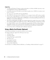
... • Music MP3 files can erase the data on page 95. 20 Setting Up and Using Your Computer The Media Card Reader supports the following memory types: • xD-Picture Card • SmartMedia (SMC) • CompactFlash Type I and II (CF I/II) • MicroDrive Card •...; SecureDigital Card (SD) • MultiMediaCard (MMC) • Memory Stick (MS/MS Pro) For information on installing a Media Card Reader, see the documentation provided with CD recording techniques. For a list of the blank space...
... • Music MP3 files can erase the data on page 95. 20 Setting Up and Using Your Computer The Media Card Reader supports the following memory types: • xD-Picture Card • SmartMedia (SMC) • CompactFlash Type I and II (CF I/II) • MicroDrive Card •...; SecureDigital Card (SD) • MultiMediaCard (MMC) • Memory Stick (MS/MS Pro) For information on installing a Media Card Reader, see the documentation provided with CD recording techniques. For a list of the blank space...
Owner's Manual
Page 21
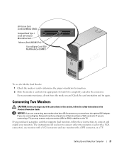
xD-Picture Card and SmartMedia (SMC) CompactFlash Type I and II (CF I/II) and MicroDrive Card Memory Stick (MS/MS Pro) SecureDigital Card (SD)/ MultiMediaCard (MMC) To use the Media Card Reader: 1 Check the media or card to the TV. Setting Up ...
xD-Picture Card and SmartMedia (SMC) CompactFlash Type I and II (CF I/II) and MicroDrive Card Memory Stick (MS/MS Pro) SecureDigital Card (SD)/ MultiMediaCard (MMC) To use the Media Card Reader: 1 Check the media or card to the TV. Setting Up ...
Owner's Manual
Page 25
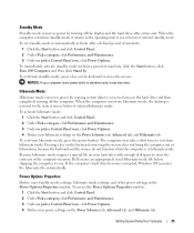
To immediately activate standby mode without a period of the computer memory, Dell creates an appropriately sized hibernate mode file before it may take a short time to you. To exit from hibernate mode, the desktop is in hibernate ...
To immediately activate standby mode without a period of the computer memory, Dell creates an appropriately sized hibernate mode file before it may take a short time to you. To exit from hibernate mode, the desktop is in hibernate ...
Owner's Manual
Page 38
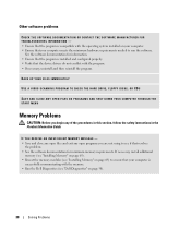
...DRIVE, FLOPPY DISKS, OR CDS SAVE AND CLOSE ANY OPEN FILES OR PROGRAMS AND SHUT DOWN YOUR COMPUTER THROUGH THE START MENU Memory Problems CAUTION: Before you are not using to see if that resolves the problem. • See the software documentation for information...DOCUMENTATION OR CONTACT THE SOFTWARE MANUFACTURER FOR TROUBLESHOOTING INFORMATION - • Ensure that the program is successfully communicating with the memory. • Run the Dell Diagnostics (see "Dell Diagnostics" on your computer. • Ensure that your computer is compatible with the operating system installed on page ...
...DRIVE, FLOPPY DISKS, OR CDS SAVE AND CLOSE ANY OPEN FILES OR PROGRAMS AND SHUT DOWN YOUR COMPUTER THROUGH THE START MENU Memory Problems CAUTION: Before you are not using to see if that resolves the problem. • See the software documentation for information...DOCUMENTATION OR CONTACT THE SOFTWARE MANUFACTURER FOR TROUBLESHOOTING INFORMATION - • Ensure that the program is successfully communicating with the memory. • Run the Dell Diagnostics (see "Dell Diagnostics" on your computer. • Ensure that your computer is compatible with the operating system installed on page ...
Owner's Manual
Page 39
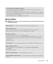
... V E R - R U N T H E H A R D W A R E TR O U B L E S H O O T E R - Mouse Problems CAUTION: Before you are following the memory installation guidelines (see "Installing Memory" on page 69). • Your computer supports DDR2 memory. IF YOU EXPERIENCE OTHER MEMORY PROBLEMS - • Reseat the memory modules (see "Installing Memory" on page 69) to highlight Shut down or Turn Off, and then press . 3 After.... See "Mouse" on page 117 for your computer, see "Memory" on page 103. • Run the Dell Diagnostics (see "Dell Diagnostics" on page 52. Connect a properly working mouse to the...
... V E R - R U N T H E H A R D W A R E TR O U B L E S H O O T E R - Mouse Problems CAUTION: Before you are following the memory installation guidelines (see "Installing Memory" on page 69). • Your computer supports DDR2 memory. IF YOU EXPERIENCE OTHER MEMORY PROBLEMS - • Reseat the memory modules (see "Installing Memory" on page 69) to highlight Shut down or Turn Off, and then press . 3 After.... See "Mouse" on page 117 for your computer, see "Memory" on page 103. • Run the Dell Diagnostics (see "Dell Diagnostics" on page 52. Connect a properly working mouse to the...
Owner's Manual
Page 41
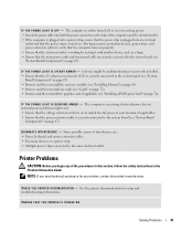
... protection devices, power strips, and power extension cables to the system board (see "System Board Components" on page 67). • Remove and then reinstall the memory modules (see "System Board Components" on . See the printer documentation for your location (if applicable). • Ensure that the main power cable and front panel... by testing it with another device, such as a lamp. • Ensure that the processor power cable is securely connected to the system board (see "Installing Memory" on page 76). I F T H E P O W E R L I G H T I S S T E A D Y A M B E R -
... protection devices, power strips, and power extension cables to the system board (see "System Board Components" on page 67). • Remove and then reinstall the memory modules (see "System Board Components" on . See the printer documentation for your location (if applicable). • Ensure that the main power cable and front panel... by testing it with another device, such as a lamp. • Ensure that the processor power cable is securely connected to the system board (see "Installing Memory" on page 76). I F T H E P O W E R L I G H T I S S T E A D Y A M B E R -
Owner's Manual
Page 47
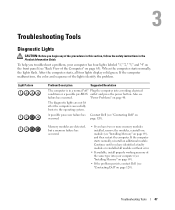
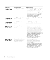
...green. A possible processor failure has Contact Dell (see "Installing Memory" on page 69), and then restart the computer. The diagnostic lights are detected, but a memory failure has occurred. • If you have two or more memory modules installed, remove the modules, reinstall.... Troubleshooting Tools Diagnostic Lights CAUTION: Before you troubleshoot a problem, your computer (see "Installing Memory" on page 69). • If the problem persists, contact Dell (see failure has occurred. Light Pattern Problem Description Suggested Resolution The computer is in the Product...
...green. A possible processor failure has Contact Dell (see "Installing Memory" on page 69), and then restart the computer. The diagnostic lights are detected, but a memory failure has occurred. • If you have two or more memory modules installed, remove the modules, reinstall.... Troubleshooting Tools Diagnostic Lights CAUTION: Before you troubleshoot a problem, your computer (see "Installing Memory" on page 69). • If the problem persists, contact Dell (see failure has occurred. Light Pattern Problem Description Suggested Resolution The computer is in the Product...
Owner's Manual
Page 48
... problem still exists, install a graphics card that you are installing are compatible with your computer (see "DDR2 Memory Overview" on page 68). • If the problem persists, contact Dell (see "Contacting Dell" on page 120). Memory modules are detected. A possible USB failure has occurred. Continue until you know works and restart the computer. •...
... problem still exists, install a graphics card that you are installing are compatible with your computer (see "DDR2 Memory Overview" on page 68). • If the problem persists, contact Dell (see "Contacting Dell" on page 120). Memory modules are detected. A possible USB failure has occurred. Continue until you know works and restart the computer. •...
Owner's Manual
Page 51
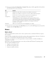
... its own set of specialized commands that controls a device such as a printer, mouse, or keyboard. Each device has its driver recognizes. Dell ships your computer to your hardware configuration for running the test. A driver acts like a translator between the device and any error conditions encountered.... 3 If you run a test from system setup, memory, and various internal tests, and it displays the information in the device list in the following table for all devices attached to you ...
... its own set of specialized commands that controls a device such as a printer, mouse, or keyboard. Each device has its driver recognizes. Dell ships your computer to your hardware configuration for running the test. A driver acts like a translator between the device and any error conditions encountered.... 3 If you run a test from system setup, memory, and various internal tests, and it displays the information in the device list in the following table for all devices attached to you ...
Owner's Manual
Page 67
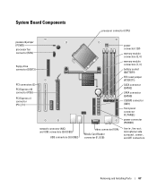
... x1 connector (PCI_E1) network connector (NIC) and USB connectors (2) (USB2) USB connectors (3) (USB2) video connector (VGA) Media Card Reader connector (F_USB) power connector (12V) memory module connectors (2, 4) memory module connectors (1, 3) battery socket (BATTERY) RTC reset jumper (RTCRST1) SATA connector (SATA2) SATA connector (SATA0) CD/DVD connector (IDE1) front-panel connector (F_PANEL) power...
... x1 connector (PCI_E1) network connector (NIC) and USB connectors (2) (USB2) USB connectors (3) (USB2) video connector (VGA) Media Card Reader connector (F_USB) power connector (12V) memory module connectors (2, 4) memory module connectors (1, 3) battery socket (BATTERY) RTC reset jumper (RTCRST1) SATA connector (SATA2) SATA connector (SATA0) CD/DVD connector (IDE1) front-panel connector (F_PANEL) power...
Owner's Manual
Page 68
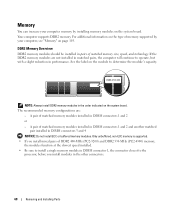
...will continue to determine the module's capacity. For additional information on the type of memory supported by your computer memory by installing memory modules on the system board. The recommended memory configurations are not installed in DIMM connectors 3 and 4 NOTICE: Do not install ...connectors 1 and 2 or - Memory You can increase your computer, see "Memory" on page 103. If the DDR2 memory modules are : - A pair of matched memory size, speed, and technology. DDR2 Memory Overview DDR2 memory modules should be installed in pairs of matched memory modules installed in the other ...
...will continue to determine the module's capacity. For additional information on the type of memory supported by your computer memory by installing memory modules on the system board. The recommended memory configurations are not installed in DIMM connectors 3 and 4 NOTICE: Do not install ...connectors 1 and 2 or - Memory You can increase your computer, see "Memory" on page 103. If the DDR2 memory modules are : - A pair of matched memory size, speed, and technology. DDR2 Memory Overview DDR2 memory modules should be installed in pairs of matched memory modules installed in the other ...
Owner's Manual
Page 69
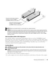
...have, even if you touch any of your body before you purchased the new modules from Dell. Addressing Memory With 4-GB Configurations Your computer supports a maximum of 4 GB of memory when you begin any new modules that the system board is on its side so that you... instructions in the Product Information Guide. Channel A: matched pair of memory modules in connectors DIMM_1 and DIMM_2 (white securing clips) Channel B: matched pair of memory modules in connectors DIMM_3 and DIMM_4 (black securing clips) NOTE: Memory purchased from Dell is less than 4 GB. You can only use a maximum of...
...have, even if you touch any of your body before you purchased the new modules from Dell. Addressing Memory With 4-GB Configurations Your computer supports a maximum of 4 GB of memory when you begin any new modules that the system board is on its side so that you... instructions in the Product Information Guide. Channel A: matched pair of memory modules in connectors DIMM_1 and DIMM_2 (white securing clips) Channel B: matched pair of memory modules in connectors DIMM_3 and DIMM_4 (black securing clips) NOTE: Memory purchased from Dell is less than 4 GB. You can only use a maximum of...
Owner's Manual
Page 70
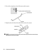
3 Press out the securing clip at each end of the module. 70 Removing and Installing Parts notch memory module cutouts (2) crossbar NOTICE: To avoid damage to the memory module, press the module straight down into the connector while you apply equal force to processor securing clips (2) connector 4 Align the notch on the bottom of the memory module connector. memory connector closest to each end of the module with the crossbar in the connector.
3 Press out the securing clip at each end of the module. 70 Removing and Installing Parts notch memory module cutouts (2) crossbar NOTICE: To avoid damage to the memory module, press the module straight down into the connector while you apply equal force to processor securing clips (2) connector 4 Align the notch on the bottom of the memory module connector. memory connector closest to each end of the module with the crossbar in the connector.
Owner's Manual
Page 71
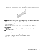
... safety instructions in "Before You Begin" on . 8 Right-click the My Computer icon and click Properties. 9 Click the General tab. 10 To verify that the memory is difficult to remove, gently ease the module back and forth to remove it into the network device and then plug it from your body... before you begin any of the memory module connector. 3 Grasp the module and pull up. If you insert the module correctly, the securing clips snap into position. You can do so by...
... safety instructions in "Before You Begin" on . 8 Right-click the My Computer icon and click Properties. 9 Click the General tab. 10 To verify that the memory is difficult to remove, gently ease the module back and forth to remove it into the network device and then plug it from your body... before you begin any of the memory module connector. 3 Grasp the module and pull up. If you insert the module correctly, the securing clips snap into position. You can do so by...
Owner's Manual
Page 103
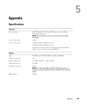
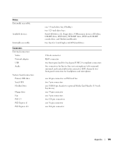
Appendix Specifications Processor Processor type Level 1 (L1) cache Level 2 (L2) cache Memory Type Memory connectors Memory capacities Minimum memory Maximum memory BIOS address Intel® Pentium® 4 5XXX and 6XXX processors with HyperThreading technology NOTE: Not all Pentium 4 processors support Hyper-Threading technology. 16 KB 1 MB ...-back SRAM 400-MHz and 533-MHz DDR2 unbuffered SDRAM four 256 MB, 512 MB, or 1 GB non-ECC 256 MB 4 GB NOTE: See "Addressing Memory With 4-GB Configurations" on page 69 to verify the amount of...
Appendix Specifications Processor Processor type Level 1 (L1) cache Level 2 (L2) cache Memory Type Memory connectors Memory capacities Minimum memory Maximum memory BIOS address Intel® Pentium® 4 5XXX and 6XXX processors with HyperThreading technology NOTE: Not all Pentium 4 processors support Hyper-Threading technology. 16 KB 1 MB ...-back SRAM 400-MHz and 533-MHz DDR2 unbuffered SDRAM four 256 MB, 512 MB, or 1 GB non-ECC 256 MB 4 GB NOTE: See "Addressing Memory With 4-GB Configurations" on page 69 to verify the amount of...
Owner's Manual
Page 105
... drive Fan PCI 2.3 PCI Express x1 PCI Express x16 one 3.5-inch drive bay (FlexBay) two 5.25-inch drive bays Serial ATA drives (2), floppy drive, USB memory devices, CD drive, CD-RW drive, DVD drive, DVD-RW drive, DVD and CD-RW combo drive, and Media Card Reader two bays for 1-inch...
... drive Fan PCI 2.3 PCI Express x1 PCI Express x16 one 3.5-inch drive bay (FlexBay) two 5.25-inch drive bays Serial ATA drives (2), floppy drive, USB memory devices, CD drive, CD-RW drive, DVD drive, DVD-RW drive, DVD and CD-RW combo drive, and Media Card Reader two bays for 1-inch...


