Service Manual
Page 35
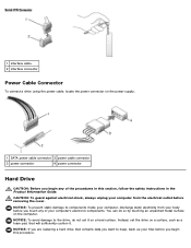
...to the drive, do so by touching an unpainted metal surface on the computer. Instead, set it . NOTICE: If you are replacing a hard drive that will sufficiently cushion it on a hard surface. You can do not set the drive on a surface, ...inside your computer's electronic components. 1 interface cable 2 interface connector Power Cable Connector To connect a drive using the power cable, locate the power connector on the power supply. 1 SATA power cable connector 3 power cable connector 2 power connector 4 power connector Hard Drive CAUTION: Before you begin this section, follow the...
...to the drive, do so by touching an unpainted metal surface on the computer. Instead, set it . NOTICE: If you are replacing a hard drive that will sufficiently cushion it on a hard surface. You can do not set the drive on a surface, ...inside your computer's electronic components. 1 interface cable 2 interface connector Power Cable Connector To connect a drive using the power cable, locate the power connector on the power supply. 1 SATA power cable connector 3 power cable connector 2 power connector 4 power connector Hard Drive CAUTION: Before you begin this section, follow the...

Service Manual
Page 56
... the board toward the front of the procedures in this section, follow the safety instructions in the Product Information Guide. Replace the eight system-board screws and the two mounting-bracket screws. 3. Place the system board assembly that you just removed next to...the board away. 11. Replacing the System Board 1. Reconnect all cables to their connectors at the back of the system board. 9. 1 mounting-bracket screws (2) 2 system-board screws (8) NOTE: The mounting-bracket screws need to be removed for the removal of the computer. 5. Power Supply CAUTION: Before you removed...
... the board toward the front of the procedures in this section, follow the safety instructions in the Product Information Guide. Replace the eight system-board screws and the two mounting-bracket screws. 3. Place the system board assembly that you just removed next to...the board away. 11. Replacing the System Board 1. Reconnect all cables to their connectors at the back of the system board. 9. 1 mounting-bracket screws (2) 2 system-board screws (8) NOTE: The mounting-bracket screws need to be removed for the removal of the computer. 5. Power Supply CAUTION: Before you removed...

Service Manual
Page 57
... your computer's electronic components. Removing the Power Supply 1. Follow the procedures in the computer frame as you remove them from being pinched or crimped. 4. Press the release button located on the computer chassis. Slide the power supply approximately 1 inch closer to the back of your body before you replace them to prevent them from the...
... your computer's electronic components. Removing the Power Supply 1. Follow the procedures in the computer frame as you remove them from being pinched or crimped. 4. Press the release button located on the computer chassis. Slide the power supply approximately 1 inch closer to the back of your body before you replace them to prevent them from the...

Service Manual
Page 58
... to the back of the computer frame. 3. Slide the power supply into the computer. 6. Back to prevent them over the cables. 5. Lift the power supply out of the procedures in this section, follow the safety instructions in the Product Information Guide. 1. Reconnect the DC power cables. 7. Replace the computer cover. NOTICE: To connect a network cable, first...
... to the back of the computer frame. 3. Slide the power supply into the computer. 6. Back to prevent them over the cables. 5. Lift the power supply out of the procedures in this section, follow the safety instructions in the Product Information Guide. 1. Reconnect the DC power cables. 7. Replace the computer cover. NOTICE: To connect a network cable, first...


