
Owner's Manual
Page 66
... You Begin" on the bottom edge of the computer. 5 Grip the sides of the procedures in this section, follow the safety instructions in a secure location. power supply system board CD or DVD drive *floppy drive hard drive *May not be present on all computers. 66 Removing and Installing Parts Inside View of...
... You Begin" on the bottom edge of the computer. 5 Grip the sides of the procedures in this section, follow the safety instructions in a secure location. power supply system board CD or DVD drive *floppy drive hard drive *May not be present on all computers. 66 Removing and Installing Parts Inside View of...

Owner's Manual
Page 106
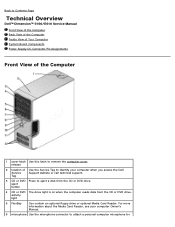
...network. Blinking green in the Product Information Guide for power-on the system board Power DC power supply: Wattage 305 W Heat dissipation 1041 BTU/hr NOTE: Heat dissipation is calculated based upon the power supply rating. solid green for important voltage setting information) Backup...no light) - The computer is a solid amber light, this indicates a problem with the power supply inside the computer. orange light - Controls and Lights Power button push button Power light green light - A good connection exists between a 10-Mbps network and the computer. Activity...
...network. Blinking green in the Product Information Guide for power-on the system board Power DC power supply: Wattage 305 W Heat dissipation 1041 BTU/hr NOTE: Heat dissipation is calculated based upon the power supply rating. solid green for important voltage setting information) Backup...no light) - The computer is a solid amber light, this indicates a problem with the power supply inside the computer. orange light - Controls and Lights Power button push button Power light green light - A good connection exists between a 10-Mbps network and the computer. Activity...
Service Manual
Page 4
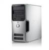
... Support website or call technical support. Back to Contents Page Technical Overview Dell™ Dimension™ 5150/E510 Service Manual Front View of the Computer Back View of the Computer Inside View of Your Computer System Board Components Power Supply DC Connector Pin Assignments Front View of Use the Service Tag to identify your computer...
... Support website or call technical support. Back to Contents Page Technical Overview Dell™ Dimension™ 5150/E510 Service Manual Front View of the Computer Back View of the Computer Inside View of Your Computer System Board Components Power Supply DC Connector Pin Assignments Front View of Use the Service Tag to identify your computer...

Service Manual
Page 9
Power Supply DC Connector Pin Assignments
Power Supply DC Connector Pin Assignments
Service Manual
Page 15
...in sleep state; Blinking amber indicates a problem with the system board (see "Diagnostic Lights") AUX_PWR on the system board Power DC power supply: Wattage 305 W If the system cannot boot and there is not detecting a physical connection to the network. yellow blinking light ...120-pin connectors one 36-pin connector one 164-pin connector Controls and Lights Power button push button Power light green light - The computer is a solid amber light, this indicates a problem with the power supply inside the computer. A good connection exists adapter) between a 100-Mbps ...
...in sleep state; Blinking amber indicates a problem with the system board (see "Diagnostic Lights") AUX_PWR on the system board Power DC power supply: Wattage 305 W If the system cannot boot and there is not detecting a physical connection to the network. yellow blinking light ...120-pin connectors one 36-pin connector one 164-pin connector Controls and Lights Power button push button Power light green light - The computer is a solid amber light, this indicates a problem with the power supply inside the computer. A good connection exists adapter) between a 100-Mbps ...
Service Manual
Page 18
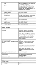
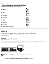
.... Back to Contents Page Removing and Installing Parts Dell™ Dimension™ 5150/E510 Service Manual Memory Cards Drive Panel Front Panel Drives Hard Drive Floppy Drive Media Card Reader (Optional) CD/DVD Drive Heat Sink Assembly Processor Fan Assembly Front I/O Panel System Board Power Supply Memory You can increase your computer memory by your...
.... Back to Contents Page Removing and Installing Parts Dell™ Dimension™ 5150/E510 Service Manual Memory Cards Drive Panel Front Panel Drives Hard Drive Floppy Drive Media Card Reader (Optional) CD/DVD Drive Heat Sink Assembly Processor Fan Assembly Front I/O Panel System Board Power Supply Memory You can increase your computer memory by your...
Service Manual
Page 35
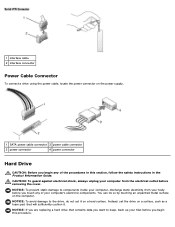
... outlet before you begin any of the procedures in this procedure. 1 interface cable 2 interface connector Power Cable Connector To connect a drive using the power cable, locate the power connector on the power supply. 1 SATA power cable connector 3 power cable connector 2 power connector 4 power connector Hard Drive CAUTION: Before you begin this section, follow the safety instructions in the Product...
... outlet before you begin any of the procedures in this procedure. 1 interface cable 2 interface connector Power Cable Connector To connect a drive using the power cable, locate the power connector on the power supply. 1 SATA power cable connector 3 power cable connector 2 power connector 4 power connector Hard Drive CAUTION: Before you begin this section, follow the safety instructions in the Product...

Service Manual
Page 56
... components and cables that it is identical. Replace any of the computer. 5. Remove the eight system-board screws and the two mounting-bracket screws. 10. Power Supply CAUTION: Before you removed from the system board. 4. 1 mounting-bracket screws (2) 2 system-board screws (8) NOTE: The mounting-bracket screws need to be removed for the...
... components and cables that it is identical. Replace any of the computer. 5. Remove the eight system-board screws and the two mounting-bracket screws. 10. Power Supply CAUTION: Before you removed from the system board. 4. 1 mounting-bracket screws (2) 2 system-board screws (8) NOTE: The mounting-bracket screws need to be removed for the...

Service Manual
Page 57
... surface on the floor of your body before you touch any of the computer frame. 6. Slide the power supply approximately 1 inch closer to the front of the DC power cables underneath the routing clips in "Before You Begin." 2. Follow the procedures in the computer frame as...the system board and the drives. 1 release button 2 power supply 3 screws (4) 4 AC power connector NOTICE: Note the routing of the computer. Disconnect the DC power cables from being pinched or crimped. 4. Remove the four screws that attach the power supply to prevent them from the system board and drives. ...
... surface on the floor of your body before you touch any of the computer frame. 6. Slide the power supply approximately 1 inch closer to the front of the DC power cables underneath the routing clips in "Before You Begin." 2. Follow the procedures in the computer frame as...the system board and the drives. 1 release button 2 power supply 3 screws (4) 4 AC power connector NOTICE: Note the routing of the computer. Disconnect the DC power cables from being pinched or crimped. 4. Remove the four screws that attach the power supply to prevent them from the system board and drives. ...

Service Manual
Page 58
Reattach the screws that secure the power supply to the back of the computer. Replace the computer cover. NOTICE: You must route the DC power cables properly through the routing clips, and press the clips to electrical outlets, and turn them from being pinched or crimped. 4.... connect a network cable, first plug the cable into the network port or device and then plug the cable into place. 2. Slide the power supply into the computer. 6. 7. Lift the power supply out of the computer frame. 3. Replacing the Power Supply CAUTION: Before you replace the cables to Contents Page
Reattach the screws that secure the power supply to the back of the computer. Replace the computer cover. NOTICE: You must route the DC power cables properly through the routing clips, and press the clips to electrical outlets, and turn them from being pinched or crimped. 4.... connect a network cable, first plug the cable into the network port or device and then plug the cable into place. 2. Slide the power supply into the computer. 6. 7. Lift the power supply out of the computer frame. 3. Replacing the Power Supply CAUTION: Before you replace the cables to Contents Page

Service Manual
Page 62
... beep code and card may be faulty. See your computer Owner's Manual . Power Light Problem Description Suggested Resolution Solid green Power is not identified, contact Dell for information on how to see if the specific problem is identified. Blinking amber A power supply or system board Check the diagnostic lights to your computer or all devices...
... beep code and card may be faulty. See your computer Owner's Manual . Power Light Problem Description Suggested Resolution Solid green Power is not identified, contact Dell for information on how to see if the specific problem is identified. Blinking amber A power supply or system board Check the diagnostic lights to your computer or all devices...


