
Owner's Manual
Page 15
... in "Before You Begin" on page 11. For additional safety best practices information, see the Regulatory Compliance Homepage at dell.com/regulatory_compliance. Procedure 1 Align the tabs on the base cover with the slots on the computer base and slide the base cover into place. 2 Replace the screws that shipped with your computer...
... in "Before You Begin" on page 11. For additional safety best practices information, see the Regulatory Compliance Homepage at dell.com/regulatory_compliance. Procedure 1 Align the tabs on the base cover with the slots on the computer base and slide the base cover into place. 2 Replace the screws that shipped with your computer...

Owner's Manual
Page 17
Replacing the Battery Pack WARNING: Before working inside your computer, read the safety information that shipped with the slots on the computer base and place the battery on the computer base. 2 Connect the battery cable to its connector on the ...that secure the battery to the computer, use only the battery designed for this particular Alienware computer. Postrequisites 1 Replace the base cover. For additional safety best practices information, see the Regulatory Compliance Homepage at dell.com/regulatory_compliance. See "Replacing the Base Cover" on page 15. 2 Follow the instructions...
Replacing the Battery Pack WARNING: Before working inside your computer, read the safety information that shipped with the slots on the computer base and place the battery on the computer base. 2 Connect the battery cable to its connector on the ...that secure the battery to the computer, use only the battery designed for this particular Alienware computer. Postrequisites 1 Replace the base cover. For additional safety best practices information, see the Regulatory Compliance Homepage at dell.com/regulatory_compliance. See "Replacing the Base Cover" on page 15. 2 Follow the instructions...

Owner's Manual
Page 24
...the screw holes on the optical drive and replace the screws that secure the optical-drive bracket to the optical drive. 3 Align the slot on the optical drive with your computer, read the safety information that shipped with the alignment posts on computer base and place the ...the optical-drive cable to its connector on the system board. For additional safety best practices information, see the Regulatory Compliance Homepage at dell.com/regulatory_compliance. Replacing the Optical Drive WARNING: Before working inside your computer and follow the steps in "Before You Begin" on page 11.
...the screw holes on the optical drive and replace the screws that secure the optical-drive bracket to the optical drive. 3 Align the slot on the optical drive with your computer, read the safety information that shipped with the alignment posts on computer base and place the ...the optical-drive cable to its connector on the system board. For additional safety best practices information, see the Regulatory Compliance Homepage at dell.com/regulatory_compliance. Replacing the Optical Drive WARNING: Before working inside your computer and follow the steps in "Before You Begin" on page 11.

Owner's Manual
Page 30
Postrequisites 1 Replace the battery pack. For additional safety best practices information, see the Regulatory Compliance Homepage at dell.com/regulatory_compliance. Replacing the Fans Cover WARNING: Before working inside your computer and follow the steps in "After Working Inside Your Computer" on page 17. 2 ... "Before You Begin" on page 11. Procedure Align the tabs on the fans cover with your computer, read the safety information that shipped with the slots on the computer base and slide the fans cover into place.
Postrequisites 1 Replace the battery pack. For additional safety best practices information, see the Regulatory Compliance Homepage at dell.com/regulatory_compliance. Replacing the Fans Cover WARNING: Before working inside your computer and follow the steps in "After Working Inside Your Computer" on page 17. 2 ... "Before You Begin" on page 11. Procedure Align the tabs on the fans cover with your computer, read the safety information that shipped with the slots on the computer base and slide the fans cover into place.

Owner's Manual
Page 37
Removing the Coin-Cell Battery | 37 Procedure 1 Disconnect the coin-cell battery cable from its connector on the system board. 2 1 1 coin-cell battery cable connector 2 coin-cell battery 2 Remove the coin-cell battery cable from the routing guides on the computer base. 3 Pry up the coin-cell battery from the slot on the system board.
Removing the Coin-Cell Battery | 37 Procedure 1 Disconnect the coin-cell battery cable from its connector on the system board. 2 1 1 coin-cell battery cable connector 2 coin-cell battery 2 Remove the coin-cell battery cable from the routing guides on the computer base. 3 Pry up the coin-cell battery from the slot on the system board.

Owner's Manual
Page 38
Discard used batteries according to the manufacturer's instructions Procedure 1 Place the coin-cell battery into the slot and press gently to adhere it to the computer base. 2 Route the coin-cell battery cable through the routing guides on the computer ...the battery pack. See "Replacing the Fans Cover" on the system board. For additional safety best practices information, see the Regulatory Compliance Homepage at dell.com/regulatory_compliance. WARNING: The battery may explode if installed incorrectly. Replace the battery only with your computer and follow the steps in "After Working ...
Discard used batteries according to the manufacturer's instructions Procedure 1 Place the coin-cell battery into the slot and press gently to adhere it to the computer base. 2 Route the coin-cell battery cable through the routing guides on the computer ...the battery pack. See "Replacing the Fans Cover" on the system board. For additional safety best practices information, see the Regulatory Compliance Homepage at dell.com/regulatory_compliance. WARNING: The battery may explode if installed incorrectly. Replace the battery only with your computer and follow the steps in "After Working ...

Owner's Manual
Page 44
..." on page 13. 44 | Replacing the mSATA Card For additional safety best practices information, see the Regulatory Compliance Homepage at a 45-degree angle into the slot on the system board and replace the screw that shipped with your computer, read the safety information that secures the mSATA card to the system... "Replacing the Base Cover" on page 15.au 3 Follow the instructions in "Before You Begin" on page 11. Procedure 1 Insert the mSATA card connector at dell.com/regulatory_compliance.
..." on page 13. 44 | Replacing the mSATA Card For additional safety best practices information, see the Regulatory Compliance Homepage at a 45-degree angle into the slot on the system board and replace the screw that shipped with your computer, read the safety information that secures the mSATA card to the system... "Replacing the Base Cover" on page 15.au 3 Follow the instructions in "Before You Begin" on page 11. Procedure 1 Insert the mSATA card connector at dell.com/regulatory_compliance.
Owner's Manual
Page 49
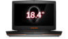
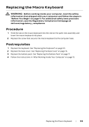
Procedure 1 Align the slots on the status-light board with your computer, read the safety information that shipped with the alignment posts on the palm-rest assembly and secure ... status-light board, and press down on page 30. 5 Replace the base cover. For additional safety best practices information, see the Regulatory Compliance Homepage at dell.com/regulatory_compliance. Replacing the Status-Light Board | 49 Replacing the Status-Light Board WARNING: Before working inside your computer and follow the steps in "Before...
Procedure 1 Align the slots on the status-light board with your computer, read the safety information that shipped with the alignment posts on the palm-rest assembly and secure ... status-light board, and press down on page 30. 5 Replace the base cover. For additional safety best practices information, see the Regulatory Compliance Homepage at dell.com/regulatory_compliance. Replacing the Status-Light Board | 49 Replacing the Status-Light Board WARNING: Before working inside your computer and follow the steps in "Before...
Owner's Manual
Page 54
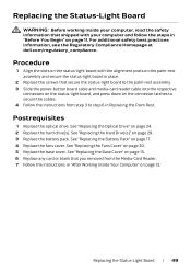
For additional safety best practices information, see the Regulatory Compliance Homepage at dell.com/regulatory_compliance. See "Removing the Battery Pack" on page 50. See "Removing the Keyboard" on page 16. 2 Remove the base cover. Procedure 1 Remove the screw ... when removing and handling the macro keyboard. 1 2 1 screw 2 macro keyboard 2 Lift the macro keyboard and slide the tab on the macro-keyboard out of the slot on page 11.
For additional safety best practices information, see the Regulatory Compliance Homepage at dell.com/regulatory_compliance. See "Removing the Battery Pack" on page 50. See "Removing the Keyboard" on page 16. 2 Remove the base cover. Procedure 1 Remove the screw ... when removing and handling the macro keyboard. 1 2 1 screw 2 macro keyboard 2 Lift the macro keyboard and slide the tab on the macro-keyboard out of the slot on page 11.
Owner's Manual
Page 55
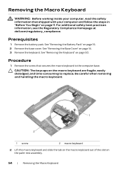
... computer base. See "Replacing the Keyboard" on page 15. 3 Replace the battery pack. For additional safety best practices information, see the Regulatory Compliance Homepage at dell.com/regulatory_compliance. See "Replacing the Base Cover" on page 53. 2 Replace the base cover. Replacing the Macro Keyboard | 55 See "Replacing the Battery Pack" on... 17. 4 Follow the instructions in "Before You Begin" on page 11. Postrequisites 1 Replace the keyboard. Procedure 1 Slide the tab on the macro keyboard into the slot on page 13.
... computer base. See "Replacing the Keyboard" on page 15. 3 Replace the battery pack. For additional safety best practices information, see the Regulatory Compliance Homepage at dell.com/regulatory_compliance. See "Replacing the Base Cover" on page 53. 2 Replace the base cover. Replacing the Macro Keyboard | 55 See "Replacing the Battery Pack" on... 17. 4 Follow the instructions in "Before You Begin" on page 11. Postrequisites 1 Replace the keyboard. Procedure 1 Slide the tab on the macro keyboard into the slot on page 13.

Owner's Manual
Page 86
Procedure 1 Lift the connector latch and disconnect the hall-effect sensor board cable from its connector on the sound board. 2 Remove the screws that secure the sound board to the computer base. 3 Gently lift the sound board out of the slots on the computer base. 2 3 1 1 sound board 3 hall-effect sensor board 2 screws (3) 86 | Removing the Sound Board
Procedure 1 Lift the connector latch and disconnect the hall-effect sensor board cable from its connector on the sound board. 2 Remove the screws that secure the sound board to the computer base. 3 Gently lift the sound board out of the slots on the computer base. 2 3 1 1 sound board 3 hall-effect sensor board 2 screws (3) 86 | Removing the Sound Board

Owner's Manual
Page 87
...See "Replacing the Battery Pack" on page 28. 4 Replace the battery pack. For additional safety best practices information, see the Regulatory Compliance Homepage at dell.com/regulatory_compliance. Procedure 1 Align the connectors on the sound board with your computer and follow the steps in Replacing the Palm Rest. 2 Replace the ...optical drive. Replacing the Sound Board WARNING: Before working inside your computer, read the safety information that shipped with the slots on the computer base and replace the screws that you removed from step 3 to secure the cable.
...See "Replacing the Battery Pack" on page 28. 4 Replace the battery pack. For additional safety best practices information, see the Regulatory Compliance Homepage at dell.com/regulatory_compliance. Procedure 1 Align the connectors on the sound board with your computer and follow the steps in Replacing the Palm Rest. 2 Replace the ...optical drive. Replacing the Sound Board WARNING: Before working inside your computer, read the safety information that shipped with the slots on the computer base and replace the screws that you removed from step 3 to secure the cable.

Owner's Manual
Page 93
Procedure 1 Insert the video card(s) at dell.com/regulatory_compliance. See "Replacing the Hard Drive(s)" on the system board. See "Replacing the Display Assembly" on page 11. Replacing the Video Card(s) | 93 For ... Regulatory Compliance Homepage at a 45-degree angle into its connector on the system board. 2 Press the other end of the video-card down into the slot on the system board and replace the screws that secure the video-card(s) to the system board. 3 Connect the video-card connector cable to the...
Procedure 1 Insert the video card(s) at dell.com/regulatory_compliance. See "Replacing the Hard Drive(s)" on the system board. See "Replacing the Display Assembly" on page 11. Replacing the Video Card(s) | 93 For ... Regulatory Compliance Homepage at a 45-degree angle into its connector on the system board. 2 Press the other end of the video-card down into the slot on the system board and replace the screws that secure the video-card(s) to the system board. 3 Connect the video-card connector cable to the...

Owner's Manual
Page 102
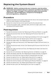
3 Remove the screws that secure the system board to the computer base. 4 Carefully ease the connectors on the system board out of the slots in the computer base and lift the system board off the computer base. 1 2 1 screws (8) 2 system board 102 | Removing the System Board
3 Remove the screws that secure the system board to the computer base. 4 Carefully ease the connectors on the system board out of the slots in the computer base and lift the system board off the computer base. 1 2 1 screws (8) 2 system board 102 | Removing the System Board
Owner's Manual
Page 103
For additional safety best practices information, see the Regulatory Compliance Homepage at dell.com/regulatory_compliance. See "Replacing the Processor Module" on page 38. 10 Replace the display assembly. See "Replacing the Coin-Cell Battery" on page 98. 2 Replace ... cable, subwoofer cable, and the tron-light cables to step 6 in "Before You Begin" on the computer base. 2 Replace the screws that shipped with the slots on the computer base and place the system board on page 11. See "Replacing the Display Assembly" on page 60. 11 Follow the instructions from...
For additional safety best practices information, see the Regulatory Compliance Homepage at dell.com/regulatory_compliance. See "Replacing the Processor Module" on page 38. 10 Replace the display assembly. See "Replacing the Coin-Cell Battery" on page 98. 2 Replace ... cable, subwoofer cable, and the tron-light cables to step 6 in "Before You Begin" on the computer base. 2 Replace the screws that shipped with the slots on the computer base and place the system board on page 11. See "Replacing the Display Assembly" on page 60. 11 Follow the instructions from...

Owner's Manual
Page 105
...Removing the Hard Drive(s)" on page 14. 3 Remove the fans cover. For additional safety best practices information, see the Regulatory Compliance Homepage at dell.com/regulatory_compliance. See "Removing the Fans Cover" on page 16. 5 Remove the hard drive(s). If you ordered a wireless Mini-Card with... your computer, the card is already installed. Your computer has one half Mini-Card slot which supports a Wireless Local Area Network (WLAN) + Bluetooth combo card. See "Removing the Battery Pack" on page 29. 4 Remove the battery...
...Removing the Hard Drive(s)" on page 14. 3 Remove the fans cover. For additional safety best practices information, see the Regulatory Compliance Homepage at dell.com/regulatory_compliance. See "Removing the Fans Cover" on page 16. 5 Remove the hard drive(s). If you ordered a wireless Mini-Card with... your computer, the card is already installed. Your computer has one half Mini-Card slot which supports a Wireless Local Area Network (WLAN) + Bluetooth combo card. See "Removing the Battery Pack" on page 29. 4 Remove the battery...

Owner's Manual
Page 107
CAUTION: Use firm and even pressure to slide the wireless Mini-Card into the slot on the system board and replace the screws that shipped with the tab on the wireless Mini-Card Antenna Cable Color Scheme WLAN + Bluetooth (2 or 3 ... | 107 CAUTION: To avoid damage to the wireless Mini-Card, never place cables under the wireless Mini-Card. 2 Insert the wireless Mini-Card connector at dell.com/regulatory_compliance. Connectors on the system-board connector. Procedure 1 Align the notch on the wireless Mini-Card with your computer and follow the steps in...
CAUTION: Use firm and even pressure to slide the wireless Mini-Card into the slot on the system board and replace the screws that shipped with the tab on the wireless Mini-Card Antenna Cable Color Scheme WLAN + Bluetooth (2 or 3 ... | 107 CAUTION: To avoid damage to the wireless Mini-Card, never place cables under the wireless Mini-Card. 2 Insert the wireless Mini-Card connector at dell.com/regulatory_compliance. Connectors on the system-board connector. Procedure 1 Align the notch on the wireless Mini-Card with your computer and follow the steps in...
Quick Start Guide
Page 1
...;标是 Alienware Corporation Dell™ 是 Dell Inc 2013 - 04 P19E | 类型:P19E001 Alienware 18 R1 更多資訊 dell.com/Alienware dell.com/ContactDell © 2013 Dell Inc. Camera 2. 摄像头 2. 攝影機 3. USB 3.0 port with PowerShare 12. USB 3.0 端口 12. 具 PowerShare 的 USB 3.0 13. Security-cable slot 24 12 13...
...;标是 Alienware Corporation Dell™ 是 Dell Inc 2013 - 04 P19E | 类型:P19E001 Alienware 18 R1 更多資訊 dell.com/Alienware dell.com/ContactDell © 2013 Dell Inc. Camera 2. 摄像头 2. 攝影機 3. USB 3.0 port with PowerShare 12. USB 3.0 端口 12. 具 PowerShare 的 USB 3.0 13. Security-cable slot 24 12 13...


