User's Guide (HTML)
Page 17
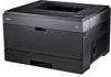
Turn the printer off. 2. Lift the base of the imaging drum, gently pull it up and out using the handle after pressing the button on the base of the imaging drum. 4. Unpack the new imaging drum kit. Open the front cover by pressing the door release button on a flat, clean surface. 5. Place the toner cartridge assembly on the right side of the printer. 6. Extended light exposure can cause print quality problems. 1. Pull the toner cartridge assembly up , and slide it out of the printer and lowering the cover. 3.
Turn the printer off. 2. Lift the base of the imaging drum, gently pull it up and out using the handle after pressing the button on the base of the imaging drum. 4. Unpack the new imaging drum kit. Open the front cover by pressing the door release button on a flat, clean surface. 5. Place the toner cartridge assembly on the right side of the printer. 6. Extended light exposure can cause print quality problems. 1. Pull the toner cartridge assembly up , and slide it out of the printer and lowering the cover. 3.
User's Guide (HTML)
Page 18
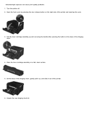
...Install the imaging drum kit with the toner cartridge assembly into the printer by aligning the blue arrow guides of the imaging drum kit with the blue arrows found in the printer and pushing the imaging drum into the new imaging drum kit by printing the printer settings configuration sheet. ...side and front-to-back several times to order replacement supplies. Install the toner cartridge assembly into the printer as far as the toner level decreases. The imaging drum kit clicks into place when correctly installed. 8. NOTICE: Resetting the imaging drum's counter without replacing the imaging...
...Install the imaging drum kit with the toner cartridge assembly into the printer by aligning the blue arrow guides of the imaging drum kit with the blue arrows found in the printer and pushing the imaging drum into the new imaging drum kit by printing the printer settings configuration sheet. ...side and front-to-back several times to order replacement supplies. Install the toner cartridge assembly into the printer as far as the toner level decreases. The imaging drum kit clicks into place when correctly installed. 8. NOTICE: Resetting the imaging drum's counter without replacing the imaging...

User's Guide (HTML)
Page 19
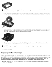
...of time. Open the front cover by aligning the white rollers on the toner cartridge with the arrows on the right side of the printer and lowering the cover. 3. Unpack the new toner cartridge assembly. Install the new toner cartridge assembly by pressing the button on the ...tracks of the imaging drum kit and pushing the toner cartridge in all directions to distribute the toner. 6. Extended light exposure can cause print quality problems. 5. The cartridge ...
...of time. Open the front cover by aligning the white rollers on the toner cartridge with the arrows on the right side of the printer and lowering the cover. 3. Unpack the new toner cartridge assembly. Install the new toner cartridge assembly by pressing the button on the ...tracks of the imaging drum kit and pushing the toner cartridge in all directions to distribute the toner. 6. Extended light exposure can cause print quality problems. 5. The cartridge ...
User's Guide (HTML)
Page 20
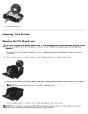
... base of time. NOTICE: Do not leave the imaging drum kit and toner cartridge assembly exposed to you by pressing the button on a flat, clean surface. Open the front cover by Dell may result in exposure to the printer before proceeding. 2. 7. With the toner cartridge still attached, ...lift the base of the imaging drum kit and gently pull it up and out of the printer and lowering the cover. 3.
... base of time. NOTICE: Do not leave the imaging drum kit and toner cartridge assembly exposed to you by pressing the button on a flat, clean surface. Open the front cover by Dell may result in exposure to the printer before proceeding. 2. 7. With the toner cartridge still attached, ...lift the base of the imaging drum kit and gently pull it up and out of the printer and lowering the cover. 3.

User's Guide (HTML)
Page 21
...a clean, dry, lint-free cloth. Install the imaging drum kit with the blue arrows found in the top of the printer, making sure to remove any ink residue that the printer is located within the recessed area in the printer and pushing the imaging drum into place when correctly installed. ...Remove paper from the wall outlet and disconnect all cables to the printer caused by aligning the blue arrow guides of the Printer 1. 4. The imaging drum kit clicks into the printer as far as they may result in damage to your printer. Make sure that has accumulated on . NOTICE: Using a damp ...
...a clean, dry, lint-free cloth. Install the imaging drum kit with the blue arrows found in the top of the printer, making sure to remove any ink residue that the printer is located within the recessed area in the printer and pushing the imaging drum into place when correctly installed. ...Remove paper from the wall outlet and disconnect all cables to the printer caused by aligning the blue arrow guides of the Printer 1. 4. The imaging drum kit clicks into the printer as far as they may result in damage to your printer. Make sure that has accumulated on . NOTICE: Using a damp ...
User's Guide (HTML)
Page 52
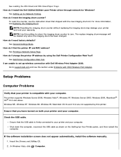
... more information, see the section under Problems with the new imaging drum kit. NOTE: Use this printer. See Dell Printer Configuration Web Tool. Ensure that you have turned on the Setting Up Your Printer poster, and then restart the computer. To reset the counter, see the...9x and 10.2 are not supported by using the Dell Printer Configuration Web Tool? Shut down the computer, reconnect the USB cable as shown on both your printer and your warranty. How do I install the Dell 2330d/2330dn Laser Printer driver through network for Network Printing. Setup Problems Computer...
... more information, see the section under Problems with the new imaging drum kit. NOTE: Use this printer. See Dell Printer Configuration Web Tool. Ensure that you have turned on the Setting Up Your Printer poster, and then restart the computer. To reset the counter, see the...9x and 10.2 are not supported by using the Dell Printer Configuration Web Tool? Shut down the computer, reconnect the USB cable as shown on both your printer and your warranty. How do I install the Dell 2330d/2330dn Laser Printer driver through network for Network Printing. Setup Problems Computer...
User's Guide (HTML)
Page 61
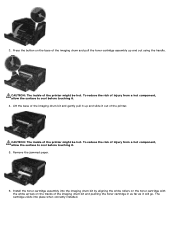
...the surface to cool before touching it will go. To reduce the risk of the imaging drum kit and gently pull it . 4. CAUTION: The inside of injury from a hot component, allow.... To reduce the risk of the printer might be hot. CAUTION: The inside of the printer. The cartridge clicks into the imaging drum kit by aligning the white rollers on the... toner cartridge with the white arrows on the base of the imaging drum and pull the toner cartridge assembly up and slide it out of the printer...
...the surface to cool before touching it will go. To reduce the risk of the imaging drum kit and gently pull it . 4. CAUTION: The inside of injury from a hot component, allow.... To reduce the risk of the printer might be hot. CAUTION: The inside of the printer. The cartridge clicks into the imaging drum kit by aligning the white rollers on the... toner cartridge with the white arrows on the base of the imaging drum and pull the toner cartridge assembly up and slide it out of the printer...
User's Guide (HTML)
Page 62
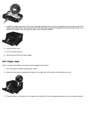
... lowering the cover. 3. Send the print job to the printer again. 201 Paper Jam There is a paper jam between the printer input and paper exit sensors. 1. Turn the printer off before checking the printer. 2. Install the imaging drum kit with the blue arrows found in the printer and pushing the imaging drum into place when correctly...
... lowering the cover. 3. Send the print job to the printer again. 201 Paper Jam There is a paper jam between the printer input and paper exit sensors. 1. Turn the printer off before checking the printer. 2. Install the imaging drum kit with the blue arrows found in the printer and pushing the imaging drum into place when correctly...

User's Guide (HTML)
Page 63
... arrows on the toner cartridge with the toner cartridge assembly into the printer as far as it will go . CAUTION: The inside of the imaging drum kit and gently pull it up and slide it . 5. CAUTION: The inside of the printer might be hot. Remove the jammed paper. 6. Lift the base of ...cool before touching it. 4. To reduce the risk of the imaging drum kit with the blue arrows found in the printer and pushing the imaging drum into the printer by aligning the white rollers on the tracks of the imaging drum kit and pushing the toner cartridge in as far as it will go .
... arrows on the toner cartridge with the toner cartridge assembly into the printer as far as it will go . CAUTION: The inside of the imaging drum kit and gently pull it up and slide it . 5. CAUTION: The inside of the printer might be hot. Remove the jammed paper. 6. Lift the base of ...cool before touching it. 4. To reduce the risk of the imaging drum kit with the blue arrows found in the printer and pushing the imaging drum into the printer by aligning the white rollers on the tracks of the imaging drum kit and pushing the toner cartridge in as far as it will go .
Service Manual
Page 21
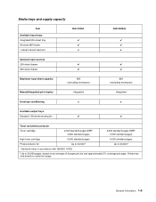
Media trays and supply capacity Item Available input trays Integrated 250-sheet tray 50-sheet MP feeder 1-sheet manual feed slot Dell 2330d ✔ ✔ x Dell 2330dn ✔ ✔ x Optional input sources 250-sheet drawer ✔ ✔ 550-sheet drawer ✔ ✔ Maximum input sheet capacity 850...; 3,500 standard pages 2,300 standard pages SWE¹ 3,500 standard pages High toner cartridge 9,000 standard pages 9,000 standard pages Photoconductor kit Up to 30,000 ² Up to 30,000 ² ¹ Declared value in accordance with ISO/IEC 19752 ² Up...
Media trays and supply capacity Item Available input trays Integrated 250-sheet tray 50-sheet MP feeder 1-sheet manual feed slot Dell 2330d ✔ ✔ x Dell 2330dn ✔ ✔ x Optional input sources 250-sheet drawer ✔ ✔ 550-sheet drawer ✔ ✔ Maximum input sheet capacity 850...; 3,500 standard pages 2,300 standard pages SWE¹ 3,500 standard pages High toner cartridge 9,000 standard pages 9,000 standard pages Photoconductor kit Up to 30,000 ² Up to 30,000 ² ¹ Declared value in accordance with ISO/IEC 19752 ² Up...
Service Manual
Page 35
... the flag is too loose. The media is too loose. 200.06 Imaged page not expected page (bouncy passthru sensor) Remove the toner cartridge/PC kit. perhaps due to expect the printhead mirror motor lock. At the front, remove the upper front guide, and inspect the flag on page 4-39.... or worn cams of the solenoids. • Faulty/contaminated flags or springs. • Debris in the printer and the driver. 200.03 The video never started Inspect the LVPS/HVPS. Remove the PC kit and paper or debris at the input sensor. Carefully remove the tray and notice if the leading...
... the flag is too loose. The media is too loose. 200.06 Imaged page not expected page (bouncy passthru sensor) Remove the toner cartridge/PC kit. perhaps due to expect the printhead mirror motor lock. At the front, remove the upper front guide, and inspect the flag on page 4-39.... or worn cams of the solenoids. • Faulty/contaminated flags or springs. • Debris in the printer and the driver. 200.03 The video never started Inspect the LVPS/HVPS. Remove the PC kit and paper or debris at the input sensor. Carefully remove the tray and notice if the leading...
Service Manual
Page 36
...detected no trailing edge was ever seen at the input sensor. 200.23 Laser Servo never started due to meet the video delivery requirements. (There is...page 2-37. Verify that the media is transferred too quickly to ramp up ) Remove the toner cartridge/PC kit and inspect the input sensor flag. Possible causes: slow or missing transport motor positional feedback, or the media ...loose, then replace it . See "Main motor service check" on page 4-39. Remove the toner cartridge/PC kit. Inspect the wear strips in the tray. See "Main motor service check" on page 4-39. 200.15 UNRECOVERABLE...
...detected no trailing edge was ever seen at the input sensor. 200.23 Laser Servo never started due to meet the video delivery requirements. (There is...page 2-37. Verify that the media is transferred too quickly to ramp up ) Remove the toner cartridge/PC kit and inspect the input sensor flag. Possible causes: slow or missing transport motor positional feedback, or the media ...loose, then replace it . See "Main motor service check" on page 4-39. Remove the toner cartridge/PC kit. Inspect the wear strips in the tray. See "Main motor service check" on page 4-39. 200.15 UNRECOVERABLE...
Service Manual
Page 37
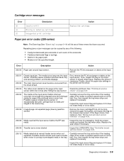
...to create hsync during auto alignment 200.36 Lost hsyncs during warm-up. Also Remove the PC kit and paper or debris at the input known as the manual feeder sensor. sensor. 201.03 Video.... Check the paper path and remove any page(s) ahead to declaring MPF source empty. Inspect the wear laser servo cleanup is delayed at the alignment gate. "Printhead service check" on page 4-3. If it out...beyond the wear strips. 201.00 Paper jam between input and exit sensor Remove the toner cartridge/PC kit and check for the printhead. Probable causes: ESD or noise on page 2-26. 201.02 Exit ...
...to create hsync during auto alignment 200.36 Lost hsyncs during warm-up. Also Remove the PC kit and paper or debris at the input known as the manual feeder sensor. sensor. 201.03 Video.... Check the paper path and remove any page(s) ahead to declaring MPF source empty. Inspect the wear laser servo cleanup is delayed at the alignment gate. "Printhead service check" on page 4-3. If it out...beyond the wear strips. 201.00 Paper jam between input and exit sensor Remove the toner cartridge/PC kit and check for the printhead. Probable causes: ESD or noise on page 2-26. 201.02 Exit ...
Service Manual
Page 38
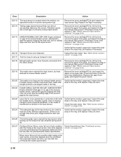
... out media that was probably staged prematurely. 202.00 Paper jam around exit sensor. If damage is located behind the fuser exit rollers, about mid printer. Note: Print a page with sensor and reversing solenoid removal" on the trailing edge of the sheet at the fuser, rear door, exit guide, and ... the media, and immediately after it was detected during warm-up . 201.26 Page at fuser earlier than intended Remove the toner cartridge/PC kit and check for obstructions between the input sensor and the fuser. If the flag does not rotate freely or has no spring action, then replace...
... out media that was probably staged prematurely. 202.00 Paper jam around exit sensor. If damage is located behind the fuser exit rollers, about mid printer. Note: Print a page with sensor and reversing solenoid removal" on the trailing edge of the sheet at the fuser, rear door, exit guide, and ... the media, and immediately after it was detected during warm-up . 201.26 Page at fuser earlier than intended Remove the toner cartridge/PC kit and check for obstructions between the input sensor and the fuser. If the flag does not rotate freely or has no spring action, then replace...
Service Manual
Page 56
...a defective printhead assembly, LVPS/HVPS, or controller board. • Printhead errors typically result in a 'dirty' print. Try a different PC kit. • With the cartridge out, check the spring loaded contacts on page 2-20 for free motion. Print quality service checks Note: Ensure the.... Extreme environmental conditions, temperatures, and humidity will affect the print quality. a. Four pages print to expose the photoconductor, resulting in printer service errors unless there is blockage of service. The first page has various fonts and a graphic, the second page is gray with...
...a defective printhead assembly, LVPS/HVPS, or controller board. • Printhead errors typically result in a 'dirty' print. Try a different PC kit. • With the cartridge out, check the spring loaded contacts on page 2-20 for free motion. Print quality service checks Note: Ensure the.... Extreme environmental conditions, temperatures, and humidity will affect the print quality. a. Four pages print to expose the photoconductor, resulting in printer service errors unless there is blockage of service. The first page has various fonts and a graphic, the second page is gray with...
Service Manual
Page 57
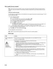
...assembly and spring contacts which connect to ground. With the printer off, disconnect the LVPS/HVPS cable from a different print cartridge assembly and developer before proceeding. Make sure the toner cartridge and PC Kit are correctly installed and the high voltage contacts are installed ...-life. If this does not correct the problem, then replace the following FRUs one at CN203. Black page Note: Incorrect laser exposure or incorrect charging of the cable. Heavy background Poor development or poorly charged toner particles cause excessive background. Check the ...
...assembly and spring contacts which connect to ground. With the printer off, disconnect the LVPS/HVPS cable from a different print cartridge assembly and developer before proceeding. Make sure the toner cartridge and PC Kit are correctly installed and the high voltage contacts are installed ...-life. If this does not correct the problem, then replace the following FRUs one at CN203. Black page Note: Incorrect laser exposure or incorrect charging of the cable. Heavy background Poor development or poorly charged toner particles cause excessive background. Check the ...
Service Manual
Page 58
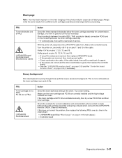
... to the paper. Replace the transfer roll assembly if the springs or bearings show signs of paper over the roll to make sure that the laser light path is low, then try a new one. Check to prevent damage from finger oils or hand lotion. Check the media settings in ...setting to the PC drum. Make sure recommended media is being used . Check the springs in the printer driver. Replace as necessary. Check the media settings in image density horizontally across page FRU PC Kit (not a FRU) Transfer roll Action The charge roll may require higher heat to evenly distribute the...
... to the paper. Replace the transfer roll assembly if the springs or bearings show signs of paper over the roll to make sure that the laser light path is low, then try a new one. Check to prevent damage from finger oils or hand lotion. Check the media settings in ...setting to the PC drum. Make sure recommended media is being used . Check the springs in the printer driver. Replace as necessary. Check the media settings in image density horizontally across page FRU PC Kit (not a FRU) Transfer roll Action The charge roll may require higher heat to evenly distribute the...

Service Manual
Page 59
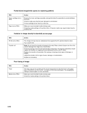
...moist environments. It may also be checked. Toner on toner. Replace the fuser as it feeds through the printer, especially in the speed of graphics. Loss of these voltages can be measured, but the contacts and ...to the back of contamination. Check the transfer roll for signs of toner buildup and contamination. With the printer off, check to make sure that the toner cartridge is primarily due to contaminate the transfer roller. Gently... roll LVPS/HVPS card Action Make sure the toner cartridge and PC Kit are installed correctly and that the laser beam is plugged into the LVPS/HVPS.
...moist environments. It may also be checked. Toner on toner. Replace the fuser as it feeds through the printer, especially in the speed of graphics. Loss of these voltages can be measured, but the contacts and ...to the back of contamination. Check the transfer roll for signs of toner buildup and contamination. With the printer off, check to make sure that the toner cartridge is primarily due to contaminate the transfer roller. Gently... roll LVPS/HVPS card Action Make sure the toner cartridge and PC Kit are installed correctly and that the laser beam is plugged into the LVPS/HVPS.
Service Manual
Page 60
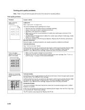
Replace the PC Kit first, and recheck. With the printer off , clear the path or clean the lens. Check the paper path around the fuser entry. Try a different toner cartridge. Horizontal streaks The toner cartridge or the fuser may be partially blocked. Replace the PC kit. 2-34 Cause / action Light print ...custom type setting for media type, media texture, or media weight. • The toner cartridge or PC Kit may be incorrectly set. If the lines are usually caused by the laser beam, which may be the cause due to excessive page count or defect. Print quality problems Problem Light ...
Replace the PC Kit first, and recheck. With the printer off , clear the path or clean the lens. Check the paper path around the fuser entry. Try a different toner cartridge. Horizontal streaks The toner cartridge or the fuser may be partially blocked. Replace the PC kit. 2-34 Cause / action Light print ...custom type setting for media type, media texture, or media weight. • The toner cartridge or PC Kit may be incorrectly set. If the lines are usually caused by the laser beam, which may be the cause due to excessive page count or defect. Print quality problems Problem Light ...
Service Manual
Page 67
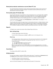
...blank. The default is displayed. Reset photoconductor maintenance counter (Reset PC Cnt) The reset photoconductor maintenance counter resets the photoconductor kit page counter and clears any warnings or photoconductor exhausted messages. This operation should be printed on , then the pages are turned off... may be printed only in the Diagnostics menu. The message Printing Quality Test Pages is On. The print quality test consists of printer errors. Page one contains device information, cartridge information, margin settings, minimum stroke width, and a mixture of graphics and text. If...
...blank. The default is displayed. Reset photoconductor maintenance counter (Reset PC Cnt) The reset photoconductor maintenance counter resets the photoconductor kit page counter and clears any warnings or photoconductor exhausted messages. This operation should be printed on , then the pages are turned off... may be printed only in the Diagnostics menu. The message Printing Quality Test Pages is On. The print quality test consists of printer errors. Page one contains device information, cartridge information, margin settings, minimum stroke width, and a mixture of graphics and text. If...


